
Antenna Housing Mold Components, Machined to Your Drawing
Move antenna housing mold components from DFM review to inspected CNC machining, EDM, grinding, and documented delivery.
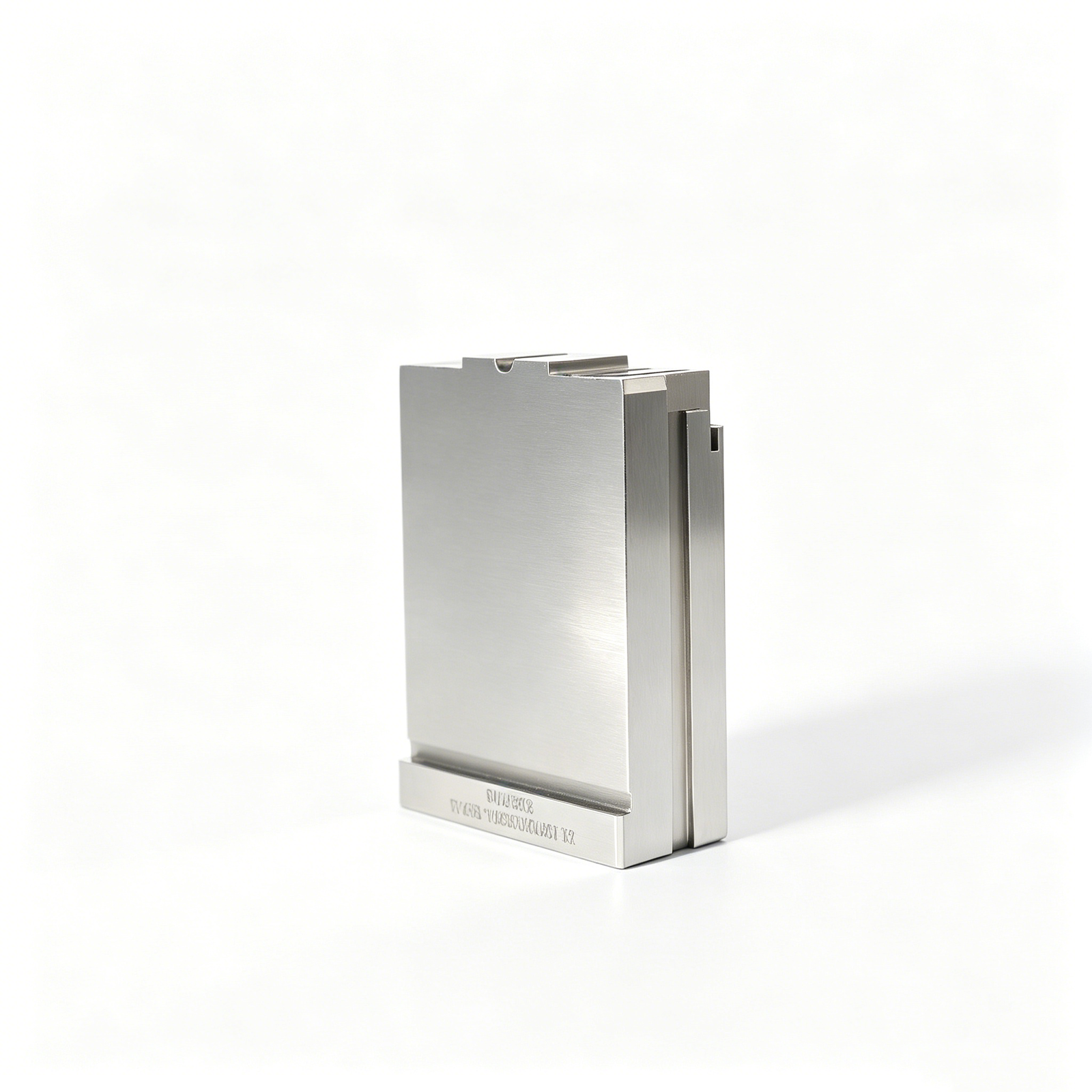
Representative Antenna Housing Mold Components







Related Configurable Component Families and Quotation






Why Teams Choose SUUXIANG for Antenna Housing Mold Components
Engineering decisions stay visible from initial drawing review through inspection documentation and delivery coordination.
Drawing Review First
We review drawings, models, datums, materials, and critical dimensions before quoting antenna housing mold components or committing to a process route.
Practical DFM Input
DFM discussion identifies machining access, wall conditions, tool paths, EDM needs, and tolerance risks that can affect manufacturability.
Coordinated Process Routes
CNC machining, wire EDM, sinker EDM, precision grinding, and fitting are planned around geometry, stock allowance, and functional interfaces.
Inspection Planned Early
Inspection requirements are aligned with critical features, datum strategy, measurement methods, and reporting expectations before production begins.
Revision Control
Drawing revisions, clarification points, and approved production information remain visible, helping teams avoid preventable discrepancies during manufacturing.
Traceable Communication
Project updates connect technical questions, process decisions, inspection evidence, and delivery coordination so sourcing and quality teams can follow progress.
Antenna Housing Mold Components and Tooling Families
Drawing-driven component families for antenna housings, connector tooling, precision molds, and custom parts, planned around critical dimensions, process access, and inspection requirements.

CNC Machining Services
Precision CNC machining services for drawing-based parts requiring coordinated milling, turning, EDM, grinding, fitting, and inspection. Process routes are reviewed against material, geometry, critical dimensions, surface requirements, quantity, and delivery expectations before production commitments.
Upload a Drawing
CNC Milling
Custom CNC milling services for prismatic parts, plates, inserts, housings, and tooling details. Drawing review considers datum definition, tool access, pocket geometry, wall conditions, machining allowance, surface requirements, and dimensions that require inspection planning.
Upload a Drawing
CNC Turning
Precision CNC turning services for rotational or concentric components such as pins, sleeves, bushings, shafts, and locating features. Requirements should define material, diameters, runout or concentricity priorities, thread details, surface condition, and mating-component context.
Upload a Drawing
5-Axis Machining
5-axis CNC machining for complex geometry where multi-angle access can reduce setups or reach difficult features. Feasibility depends on part clamping, tool reach, datum strategy, material condition, tolerance stack, surface requirements, and a review of critical features.
Upload a Drawing
Swiss & Micro Machining
Swiss machining and micro machining for small, slender, or detail-dense components such as fine pins, shafts, sleeves, and connector-related features. Drawing review addresses stock form, feature size, length-to-diameter relationships, tolerances, surface needs, and inspection method.
Upload a Drawing
Wire & Sinker EDM
Wire EDM and sinker EDM services for hardened materials, sharp internal profiles, narrow slots, difficult corners, and features unsuitable for conventional tool access. Electrode strategy, wire path, flushing conditions, finish requirements, and downstream fitting or grinding are reviewed from the drawing.
Upload a Drawing
Precision Grinding
Precision surface and profile grinding for controlled flatness, parallelism, thickness, profiles, and finishing allowances on mold and die components. The process plan considers heat-treatment sequence, grinding stock, datum surfaces, dimensional priorities, and the required inspection approach.
Upload a Drawing
Mold Core & Cavity Inserts
Precision mold core and cavity inserts configured from approved drawings and 3D models for antenna housings and related molded parts. Reviews address steel selection, parting and shutoff details, cooling interfaces, EDM or grinding needs, critical geometry, and inspection requirements.
Upload a Drawing
Ejector & Ejection Components
Ejector pins, sleeves, and ejection components produced to drawing-defined dimensions and fit requirements. A responsible review considers material and heat treatment, guiding relationship, clearance, contact geometry, surface condition, wear considerations, and the relevant mold assembly context.
Upload a Drawing
Core Pins, Guide & Locating Components
Core pins, guide pins, and locating components for repeatable mold alignment, feature formation, and controlled assembly. Drawings should identify datums, fit relationships, material condition, hardness requirements where applicable, critical diameters, mating details, and inspection priorities.
Upload a Drawing
Slides, Lifters, Gates & Mold Accessories
Mold slides, lifters, gates, and accessories configured as drawing-based tooling components rather than stock SKUs. Process planning examines travel interfaces, shutoffs, angles, wear surfaces, material condition, machining and EDM access, fitting requirements, and assembly references.
Upload a Drawing
Connector Mold Components
Precision connector mold components for feature-dense tooling where pin geometry, pitch relationships, locating references, and surface requirements affect molded-part performance. RFQs should include component drawings, assembly context, material requirements, critical dimensions, and applicable inspection expectations.
Upload a Drawing
Stamping Die Components
Precision stamping die components for drawing-controlled cutting, forming, guiding, and locating functions. The review considers material and heat-treatment requirements, working edges, clearance relationships, grinding allowances, wire-EDM strategy, mating parts, and inspection criteria.
Upload a Drawing
Injection, MIM, CIM & Overmolding Tooling
Injection, MIM, CIM, and overmolding tooling components supported within verified production scope. Requirements are assessed for mold geometry, material condition, shrinkage-related design intent, inserts or interfaces, wear areas, process route, and the documentation needed for production release.
Upload a Drawing
Machining Materials
CNC machining materials selected against the approved drawing and application requirements, including machinability, dimensional stability, strength, wear, corrosion, and heat-treatment needs. Material availability and any substitution must be confirmed before quotation and production.
Upload a Drawing
Surface Finishes & Heat Treatment
Surface finishing and heat treatment planned around functional surfaces, corrosion or wear needs, dimensional change risk, and subsequent machining or grinding. Specifications should identify finish type, target condition, masking or coverage requirements, and dimensions affected by treatment.
Upload a Drawing
Quality, Metrology & Documentation
Precision inspection, metrology, and quality documentation aligned with the order and verified inspection plan. Define critical dimensions, datums, sampling or reporting needs, measurement method expectations, revision status, and any traceability requirements before production begins.
Upload a Drawing
Prototyping & Low-Volume Production
Rapid prototyping and low-volume manufacturing for drawing-based parts and tooling components where early fit, function, process learning, or controlled quantities matter. Quote review covers revision maturity, material, critical features, inspection needs, quantity, and target delivery date.
Upload a DrawingAntenna Housing Mold Components: Material Options

Prehardened Tool Steel
A practical choice for mold bases, support blocks, and moderate-volume inserts. Prehardened tool steel machines efficiently, but the required hardness, polishing needs, and post-machining dimensional checks should be defined in the drawing review.

H13 Tool Steel
Often considered for components exposed to repeated thermal cycling, including cores, cavity inserts, and slides. Its machining route should allow for heat treatment, EDM, grinding stock, and final inspection of critical sealing and locating features.

Stainless Mold Steel
Suitable where resin moisture, storage conditions, or process environments raise corrosion concerns. Stainless mold steel can support polished cavity surfaces, while heat-treatment condition, surface finish, and corrosion requirements must be confirmed project by project.

D2 Tool Steel
A wear-focused option for inserts, gates, and features subject to abrasive filled resins or repeated contact. Its hardness and wear resistance require a planned machining, EDM, heat-treatment, and precision-grinding sequence to protect final dimensions.

Beryllium Copper Alloys
Used selectively for inserts requiring targeted heat transfer in difficult-to-cool areas. These alloys machine differently from tool steels, so tool access, feature geometry, handling requirements, and mating-surface tolerances need early review.
Antenna Housing Mold Components: Precision Process Routes

CNC Milling
Multi-axis milling develops cores, cavity inserts, slides, and structural features with controlled tool access. Toolpaths are planned around datum surfaces, wall geometry, machining allowance, and the features that require downstream EDM or grinding.

CNC Turning
Turning supports round pins, bushings, locating features, and rotational details used in antenna housing tooling. The route is selected when concentricity, shoulder locations, diameters, and mating relationships are defined on the drawing.

Wire EDM
Wire EDM produces narrow profiles, accurate cutouts, and hard-material features where conventional cutter access is limited. Wire path, start-hole placement, corner conditions, and datum references should be reviewed against the component drawing.

Sinker EDM
Sinker EDM forms deep cavities, sharp internal details, and inaccessible geometry using an electrode strategy matched to the required shape. Electrode wear, finish targets, spark allowance, and subsequent polishing or fitting requirements guide planning.

Precision Grinding
Precision grinding controls critical flatness, parallelism, thickness, and fit surfaces after the appropriate machining or heat-treatment stage. Grinding stock, datum sequence, and measurement method are aligned with the drawing’s critical dimensions.

Fitting Inspection
Fitting and inspection verify functional relationships across mating components, including clearance, alignment, and critical dimensions. SUUXIANG aligns inspection methods and reporting requirements with the agreed drawing revision and order-specific quality plan.
Antenna Housing Mold Components: Feature Options

Threaded Interfaces
Threads for fasteners, inserts, caps, or mating assemblies can be machined or prepared around the required datum scheme. Share thread standard, engagement requirements, material condition, and any post-treatment sequence for feasibility review.

Locating Features
Pins, slots, shoulders, and locating bores help control alignment between mold elements and mating antenna-housing tooling. Critical positions should be tied to clear datums so machining, EDM, grinding, and inspection can follow the intended stack.

Ejection Interfaces
Ejector-pin seats, return-pin interfaces, clearance pockets, and bearing surfaces can be configured to suit the approved ejection layout. Provide the ejection concept, contact areas, and wear considerations so access and finishing strategy can be reviewed.

Surface Finishes
Ground, machined, polished, textured, or EDM-generated surfaces can be specified where function or appearance requires them. Identify surface-critical areas, roughness expectations, release direction, and whether a finish must follow heat treatment.

Identification Markings
Part numbers, revision marks, cavity identifiers, and orientation references can support traceability during assembly and maintenance. Define marking location, character size, method preference, and cosmetic restrictions on the drawing or RFQ.

Mating Features
Sealing lands, shutoff faces, snap-fit tooling details, and connector-facing geometry require coordinated control of clearance and contact conditions. Include mating-part context and critical dimensions so the process route and inspection plan reflect the functional interface.
About SUUXIANG Precision Manufacturing
SUUXIANG is the public-facing brand of Dongguan SuuXiang Precision Mold Co., Ltd., established in 2010 in Chang’an Town, Dongguan, Guangdong, China. We help international engineering and sourcing teams convert drawings, models, and specifications into inspected custom CNC parts, precision mold components, connector tooling, and die components.
For antenna housing mold components, our planning can combine CNC milling and turning, multi-axis machining, EDM, precision grinding, fitting, and inspection according to the drawing. Before quotation or production commitments, the team reviews critical dimensions, datums, machining access, material and heat-treatment requirements, surface priorities, and documentation expectations.
Our difference is a disciplined drawing-to-inspection workflow rather than a generic parts catalogue. SUUXIANG keeps DFM discussion, process-route decisions, revision control, and inspection planning visible throughout the project, helping buyers assess manufacturability and align final evidence with the agreed order requirements.

Antenna Housing Mold Components: Critical Process Controls
DFM and Datum Strategy
SUUXIANG reviews antenna housing mold components from the drawing outward, identifying critical dimensions, datum relationships, tolerance stacks, and functional mating features before process commitments are made. This creates a clearer basis for machining sequence, inspection planning, and revision-controlled quotation.
- Confirm functional datums and critical-to-quality features
- Identify tolerance-stack risks across mating components
- Review tool access, wall conditions, and parting-related geometry
- Align drawing revisions before production release

CNC Access Planning
Complex cores, cavity inserts, slides, and locating features require more than nominal dimensions. CNC planning considers cutter reach, multi-axis access, corner conditions, clamping strategy, and stock remaining for downstream work so the intended geometry can be produced and measured reliably.
- Assess cutter reach and internal-corner limitations
- Plan workholding around datum-critical surfaces
- Sequence roughing and finishing around distortion risk
- Reserve stock where EDM or grinding follows

EDM Path and Electrode Review
Where conventional cutting cannot reach a feature or protect a sharp internal condition, SUUXIANG evaluates wire-EDM path access and electrode strategy. The review connects feature geometry, flushing space, electrode requirements, and finishing needs to a practical manufacturing route.
- Check wire entry, exit, and path-clearance requirements
- Define electrode approach for inaccessible features
- Consider EDM allowance before final finishing
- Flag geometry needing customer clarification early

Grinding and Inspection Planning
Grinding allowance and inspection method should be defined with the same care as machining. SUUXIANG plans final surfaces around heat-treatment sequence, remaining stock, measurement datum, and reporting requirements, helping teams avoid inspection results that cannot be meaningfully related to the drawing.
- Set grinding stock before heat treatment and finishing
- Link measurement points to approved drawing datums
- Clarify dimensional and surface inspection priorities
- Match final documentation to the verified inspection plan

Antenna Housing Mold Components: Drawing-Driven Review vs. a Quotation-First Workflow
Use this illustrative comparison to assess the drawing-to-inspection controls needed before selecting a manufacturing partner.
← Swipe left or right to view →
Antenna Housing Mold Components: From Drawing Review to Shipment
A controlled sequence for turning approved drawings into inspected tooling components with visible revision, quality and delivery coordination.
Review Drawing Package
SUUXIANG reviews 2D drawings, 3D models, material, quantity, application context, critical dimensions, datums, surfaces, inspection needs and requested delivery timing before quotation.
Plan Process Route
The team confirms DFM considerations, machining access, heat-treatment sequence, grinding allowance, electrode strategy, wire paths and the inspection approach for the approved revision.
Machine Critical Features
CNC milling, turning, multi-axis work or micro machining are selected as required to establish component geometry, stock conditions and accessible functional features.
EDM Grind and Fit
Wire EDM, sinker EDM, precision grinding and fitting address detailed profiles, hardened features, controlled clearances and mating relationships identified in the process plan.
Inspect Against Requirements
Inspection follows the agreed plan, verifying critical dimensions, surfaces and required records against the current drawing revision before final release and documentation preparation.
Pack and Coordinate Shipment
Released antenna housing mold components are protected for transport, matched with applicable order documentation, and coordinated with the customer’s delivery and traceability requirements.
How to Source Antenna Housing Mold Components
A disciplined workflow keeps technical requirements, revision decisions, and inspection expectations visible before production begins.
Submit Your Drawing Package
Provide 2D drawings, available 3D models, application context, quantity, target delivery date, and the antenna housing mold components or related tooling required.
Define Critical Requirements
Identify material, heat treatment, critical dimensions, datums, surface requirements, mating features, inspection reports, and any functional details that affect the machining route.
Review DFM and Quotation
Review SUUXIANG feedback on tool access, EDM or grinding needs, machining allowances, inspection planning, revision questions, and the proposed quotation or sample route.
Approve Production Details
Confirm the drawing revision, agreed process route, material requirements, quantity, quality expectations, delivery coordination, and any approved sample or first-article requirements before release.
Receive Inspected Parts
Production follows the approved plan through machining, EDM, grinding, fitting, and inspection, with final documentation aligned to the verified order and inspection requirements.
Quality Documentation for Antenna Housing Mold Components
Customer Evidence Publication Policy
Customer testimonials and case evidence are published only after customer approval and verification.
Antenna Housing Mold Components FAQ
Practical RFQ, process-planning, inspection, and delivery answers for drawing-driven tooling components.
What information should I provide for antenna housing mold components?
Can SUUXIANG quote prototype or low-volume antenna housing mold components?
How are antenna housing mold components reviewed before production?
Can you provide samples before a larger production order?
What determines the lead time for custom mold components?
Which materials and heat treatments can be used for antenna housing mold components?
What inspection reports can be requested with an order?
How are drawings and IP-sensitive files handled during quotation?
Complete Buyer’s Guide to antenna housing mold components
Use a practical decision framework to specify RF-aware tooling, compare supplier capabilities, control cost and quality risks, and avoid the design, validation, and sourcing mistakes that delay antenna-housing programs.
1. What Are Antenna Housing Mold Components?
For this guide, antenna housing mold components are drawing-driven precision tool elements that form an antenna enclosure and adjacent connector, seal, latch, or locating features. They can include forming inserts, cores, cavities, pins, slides, EDM-produced details, and ground mating faces.
Keep three RFQ items separate: the production mold is the complete assembly that runs in a molding machine; replaceable components are serviceable precision elements within that assembly; and the molded housing is the finished polymer part. The drawing should identify the relevant interfaces and any component intended for replacement after wear or revision.
RF performance may be affected when nearby wall thickness, ribs, metal features, resin, or coatings change the antenna’s electromagnetic environment. SUUXIANG therefore reviews datums, critical dimensions, parting lines, venting, shutoffs, electrode strategy, grinding stock, and inspection needs before selecting a manufacturing route.
2. Evolution of Antenna Housing Tooling
Antenna-housing tooling must balance enclosure fit, strength, appearance, and the effects of nearby walls, ribs, metal, and resin on the antenna’s electromagnetic environment.
Integrated antenna and housing assemblies can add insert location, retention, shutoff, gate, venting, and inspection considerations. Buyers should provide mating-stack and keep-out information before antenna housing mold components are designed.
Compact housings with thin walls or low-draft internal features can turn ordinary mold work into an access, cooling, ejection, and cosmetic-risk problem. DFM-first collaboration should therefore lock datums, RF keep-outs, insert sequence, sealing surfaces, finish zones, and inspection methods before steel release.
3. Types of Antenna Housing Mold Components
Antenna housing mold components should be specified by function, datum relationship, and replacement strategy. The highest-risk items are usually drawing-based parts that control thin walls, cosmetic surfaces, and RF-adjacent geometry.
| Category | Primary Role | Typical Specification |
|---|---|---|
| Cores and cavities | Form geometry | Custom drawing-based |
| Inserts | Protect local details | Custom or replaceable |
| Slides and lifters | Release undercuts | Custom motion geometry |
| Ejector parts | Release molded housing | Often standardizable |
| Guides and locators | Maintain alignment | Often standardizable |
| Cooling inserts | Control local heat | Custom drawing-based |
Forming Components
Core and cavity components create the housing’s external surfaces, internal volume, ribs, and bosses. Custom inserts localize wear-prone or revision-sensitive details without replacing a complete block.
- Specify shutoff geometry and primary datums.
- Identify cosmetic and RF-adjacent surfaces.
- Separate replaceable inserts from base blocks.
Motion And Ejection
Slides and lifters form undercuts that cannot release along the main opening direction. Ejector pins, sleeves, blades, and return elements must distribute release force without marking visible surfaces or distorting thin sections.
- Match slide travel to undercut clearance.
- Locate ejectors away from cosmetic faces.
- Define pin, sleeve, or blade contact areas.
Guidance And Thermal Control
Guide pins, bushes, interlocks, and locating elements protect alignment at parting and critical insert interfaces. Cooling-related inserts support repeatable cycle behavior where local heat removal needs controlled geometry.
- Standardize catalog guidance where suitable.
- Draw custom interlocks and cooling inserts.
- Call out sealing and service access.
4. Materials for Antenna Housing Mold Components
Material selection follows the housing resin, cosmetic target, cooling demand, and planned shot count. Antenna housing mold components should be specified by function, not by a single preferred grade.
| Material Route | Typical Role | Key Trade-Off |
|---|---|---|
| Pre-hardened steel | Cores, cavities | Machinability versus lower wear life |
| Through-hardened steel | Wear inserts, slides | Durability versus heat-treatment distortion |
| Corrosion-resistant steel | Moisture or corrosive resins | Rust resistance versus cost |
| High-conductivity alloy | Local cooling inserts | Faster heat transfer versus support needs |
| Aluminum | Prototype tools | Short lead time versus limited wear life |
Core And Cavity Steels
P20-type pre-hardened steel suits many moderate-volume cores and cavities with practical machining and repairability.
H13-type through-hardened steel better supports wear resistance and polish retention when production demand and abrasive resin justify heat treatment.
Corrosion And Thermal Choices
High-conductivity copper alloys can improve local cooling, but require controlled placement, support, and maintenance planning.
RF And Resin Review
Glass-filled resins increase wear at gates, slides, and shutoffs; hardened inserts may be more economical than hardening every component.
RF performance depends on molded-resin grade, wall consistency, fillers, coatings, and nearby metal. Confirm these inputs before locking steel.
5. Customizing Antenna Housing Mold Components
Customization begins with the molded-part drawing, not a catalog selection. For antenna housing mold components, lock RF-sensitive wall zones, metal-free clearances, and cosmetic boundaries before steel design.
| Feature | Tooling Decision | Required Input |
|---|---|---|
| Gate | Fill path and vestige zone | Approved gate-free surfaces |
| Venting | Air escape near end-of-fill | Cosmetic and burn-risk zones |
| Ejection | Pin or blade placement | No-mark and RF-sensitive areas |
| Insert Interface | Location and retention datum | Insert drawing and assembly tolerance |
Parting And Shutoff Strategy
Parting lines should avoid visible show surfaces and antenna-adjacent walls where flash or mismatch can alter assembly gaps. Draft, shutoff angle, tool access, and allowable witness lines need approval on the 3D model.
Structural And Cosmetic Features
Ribs, bosses, inserts, texture, polish, logos, gates, vents, and ejector locations require coordinated datum references. Specify whether markings are raised, recessed, laser-applied, or excluded from polished zones.
RF And Validation Inputs
RF regions require consistent nominal walls and an early review of nearby metal inserts, conductive paint, plating, or shielding. Supply the 2D drawing, 3D model, CTQ tolerances, material specification, mating parts, appearance standard, samples, and validation plan.
6. Quality Elements in Antenna Housing Mold Components
Two functional datums should locate every critical core, cavity insert, slide, and inspection setup. For antenna housing mold components, repeatability depends on matching drawing intent to machining, fitting, cooling, and measurement evidence.
Datums And Fit Control
Three datum references should govern coordinate callouts, gauge setup, and replacement-part interchangeability. Define CTQ tolerances, mating clearances, and allowable alignment variation before steel is released.
- Identify primary, secondary, and tertiary datums.
- Specify shutoff contact and flash acceptance.
- Record component IDs and drawing revisions.
Surface And Edge Integrity
One approved finish sample should define texture direction, polish level, gate-adjacent appearance, and permissible EDM witness marks. Specify edge breaks where sharp edges could gall, chip, or mark the molded surface.
- Set visible-surface defect limits.
- Define burr and sharp-edge acceptance.
- Confirm shutoff damage criteria.
Thermal Stability And Traceability
Each specified heat-treatment condition requires material identification, sequence control, and verification appropriate to the order. Confirm cooling-path cleanliness, leak checks, inspection method, report format, and replacement-component acceptance criteria.
- Tie measurements to datums and revision.
- Define cooling-test conditions.
- Separate wear limits from cosmetic limits.
7. Choosing an Antenna Housing Mold Components Manufacturer
Two documents should start supplier screening: the controlled 2D drawing and its matching 3D model. For antenna housing mold components, evaluate how a supplier turns those files into DFM questions, a process route, and inspection evidence.
| Evaluation Area | Ask | Request Evidence |
|---|---|---|
| DFM | What changes improve manufacturability? | Marked drawing and action log |
| Inspection | How are CTQs measured? | Sample inspection report |
| Traceability | How is material linked to parts? | Material-record example |
| Nonconformance | What happens after a defect? | Corrective-action workflow |
Engineering Review
Before quotation, ask which datums, critical dimensions, tool-access limits, electrode strategy, wire paths, and grinding allowances require clarification. Request a marked drawing or DFM log with revision identifiers and ownership for each action.
One engineering contact should confirm material, heat treatment, surface requirements, quantity, application context, and target date. Ask how drawing changes are acknowledged before machining begins.
Evidence Before Order
Three evidence sets matter: material traceability, first-piece inspection, and final documentation. Request sample report formats, instrument identification, measurement-method selection, and the link between reported dimensions and drawing revisions.
One nonconformance workflow should define containment, root-cause response, disposition approval, rework verification, and corrective-action timing. Ask whether prototype and low-volume orders use the same revision-control discipline.
Project Control And Confidentiality
One project plan should show milestones from drawing review through machining, EDM, grinding, fitting, inspection, and shipment. Confirm the reporting cadence, escalation contact, packaging requirements, and how delivery changes are communicated.
One confidentiality discussion should establish permitted file access, retention, return or destruction expectations, and NDA requirements. Do not assume a certification, capacity, tolerance, or lead-time claim without current project evidence.
8. Common Antenna Housing Mold Components Mistakes
One cross-functional review before steel release should involve RF, mechanical, tooling, quality, and procurement. It exposes constraints that isolated drawing checks routinely miss.
Late RF Decisions
One late RF change to resin, wall thickness, coating, or nearby metal can invalidate tuned performance after tool construction. Freeze the antenna keep-out geometry and evaluate representative materials and finishes before release.
Two teams—RF and tooling—should review gates, ribs, bosses, and joining features together. Record approved alternatives through revision control rather than relying on informal assumptions.
Incomplete Moldability Definition
Three drawing gaps cause recurring rework: incomplete tolerance stacks, insufficient draft, and vague texture callouts. The result can be binding ejection, cosmetic variation, or dimensions that cannot be inspected from stated datums.
Four items require explicit agreement: datum scheme, draft by surface, texture grade and direction, and permitted variation. Identify gate vestige and ejector-mark locations as controlled cosmetic areas before electrode and steel decisions.
Weak Supplier Controls
One unclear inspection plan creates disputes when parts meet a general drawing interpretation but fail functional assembly. Define critical dimensions, sampling or reporting expectations, measurement method, and revision-specific acceptance criteria in the RFQ.
Two quotations with different process routes are not directly comparable. Evaluate quoted price alongside material traceability, heat-treatment sequence where applicable, inspection evidence, change control, and delivery risk.
9. Launching an Antenna Housing Tooling Program
Gate 0 begins with RF bands, antenna keep-out zones, housing material, wall targets, sealing needs, and cosmetic requirements. The customer owns functional acceptance criteria; SUUXIANG records drawing revisions, critical dimensions, datums, and inspection expectations before quotation.
Freeze The Input Package
Gate 1 requires released 2D drawings, available 3D models, resin and heat-treatment requirements, quantity, and target date. Engineering approves DFM actions covering draft, tool access, gate location, electrodes, wire paths, and grinding stock.
Gate 2 releases controlled component drawings and a quotation scope. Procurement confirms commercial terms only after technical assumptions and exclusions are visible.
Prove Tool And Samples
Gate 3 approves material evidence and the inspection plan before machining. SUUXIANG supplies first-article results against identified CTQs; the buyer disposition is accept, conditional accept, or corrective action.
Gate 4 follows tool trials with molded samples validated for fit, appearance, sealing, and RF performance by the responsible customer teams. Production release requires signed sample disposition and closed deviations.
Control Engineering Changes
One change notice carries the part number, revision, reason, affected dimensions, effective date, and approver. No email-only instruction should supersede the controlled drawing.
Each change triggers impact review for tooling, electrodes, inspection, samples, cost, and delivery. SUUXIANG should acknowledge the revision received and retain matching manufacturing and inspection records.
10. Pricing Antenna Housing Mold Components
1 quotation should separate the component’s process route from the commercial assumptions behind it. For antenna housing mold components, cost changes when tool access requires multi-axis machining, wire EDM, sinker EDM, grinding, fitting, or additional electrodes.
2 drawings with different datum schemes or acceptance criteria are not comparable, even when the nominal geometry appears similar. Material condition, heat-treatment sequence, surface specification, critical dimensions, inspection report content, packing, Incoterms, currency, and target delivery date should match before comparing offers.
3 quantity tiers primarily distribute setup, programming, fixtures, electrodes, and first-article inspection across more pieces. SUUXIANG should review the current drawing package and verified production scope before confirming any price, lead time, or capability commitment.
| Pricing driver | Lower-cost indication | Higher-cost indication |
|---|---|---|
| Component type | Simple pin, insert, or locator | Core, cavity insert, slide, or fitted assembly |
| Material and heat treatment | Readily machinable, untreated material | Specified tool steel, controlled heat treatment, or post-treatment finishing |
| Precision and finish | General dimensions; machined finish | Tight critical dimensions; grinding, polishing, texture, or cosmetic requirements |
| Geometry and inspection | Open tool access; standard checks | Deep ribs, fine features, EDM access limits, CMM report, or special gauges |
| Quantity and urgency | Planned low-volume batch | Prototype quantity, revision changes, or expedited delivery |
Upload Antenna Housing Mold Components Drawings for Technical Review
Submit drawings, models, quantities, material requirements, critical dimensions, inspection needs, and your target delivery date for a disciplined quotation review.