
Precision CNC Machining for Parts and Mold Components
Plan from your drawing for precision CNC machining with CTQ review, process planning, and inspection requirements defined before production.
Representative Parts for CNC and Mold Component Manufacturing
Selected from SUUXIANG’s own product catalogue. Photos show component geometry, not material certificates, achieved tolerances or customer results. Open each part for context; your approved drawing defines the order.

Custom Flanged Stepped CNC Turned Component
Stepped diameters, a flange and a non-round base. Discuss the reference axis, shoulder locations and any secondary features.
View Component
Custom Hollow Stepped CNC Shaft
Hollow shafts with external steps and grooves. Specify the bore, mating diameters and the required relationship between them.
View Component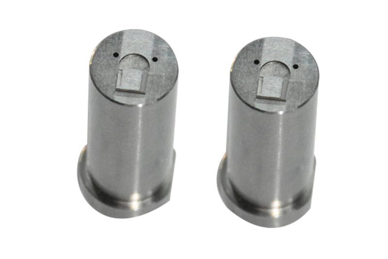
Custom End-Pocket Flanged CNC Cylinder
A flanged cylinder with an end-face pocket and small holes. Identify the pocket location, hole pattern and controlling datum.
View Component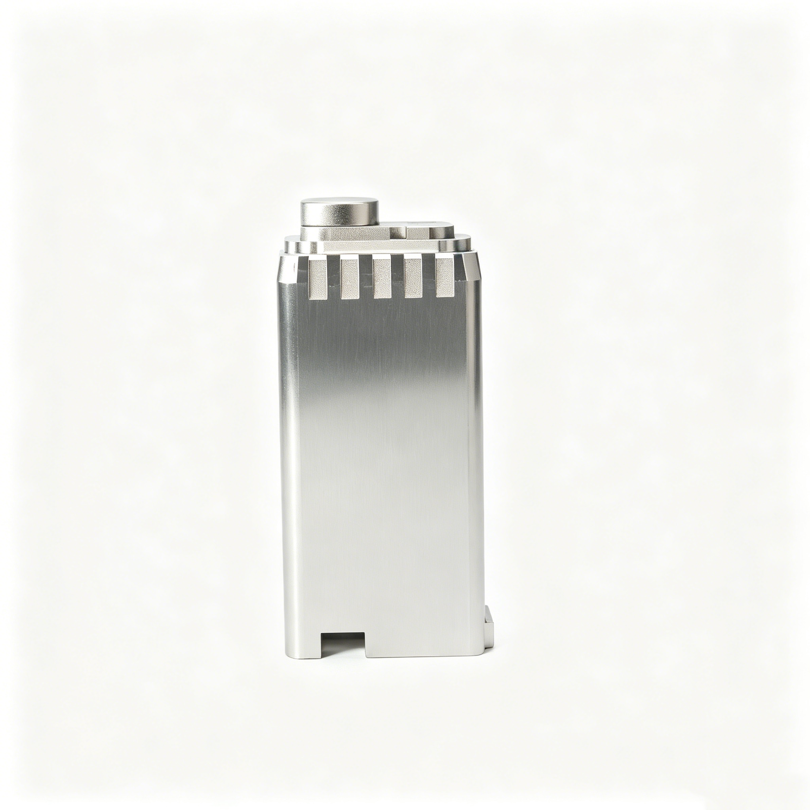
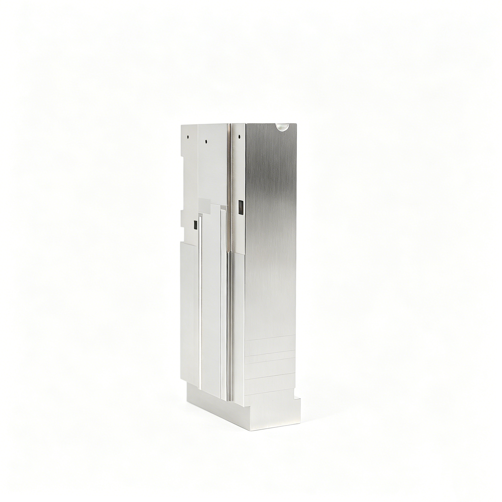
Custom Fine-Rib Connector Mold Insert
A block with repeated narrow ribs and stepped features. Identify the functional rib profile and mating surfaces in the drawing.
View Component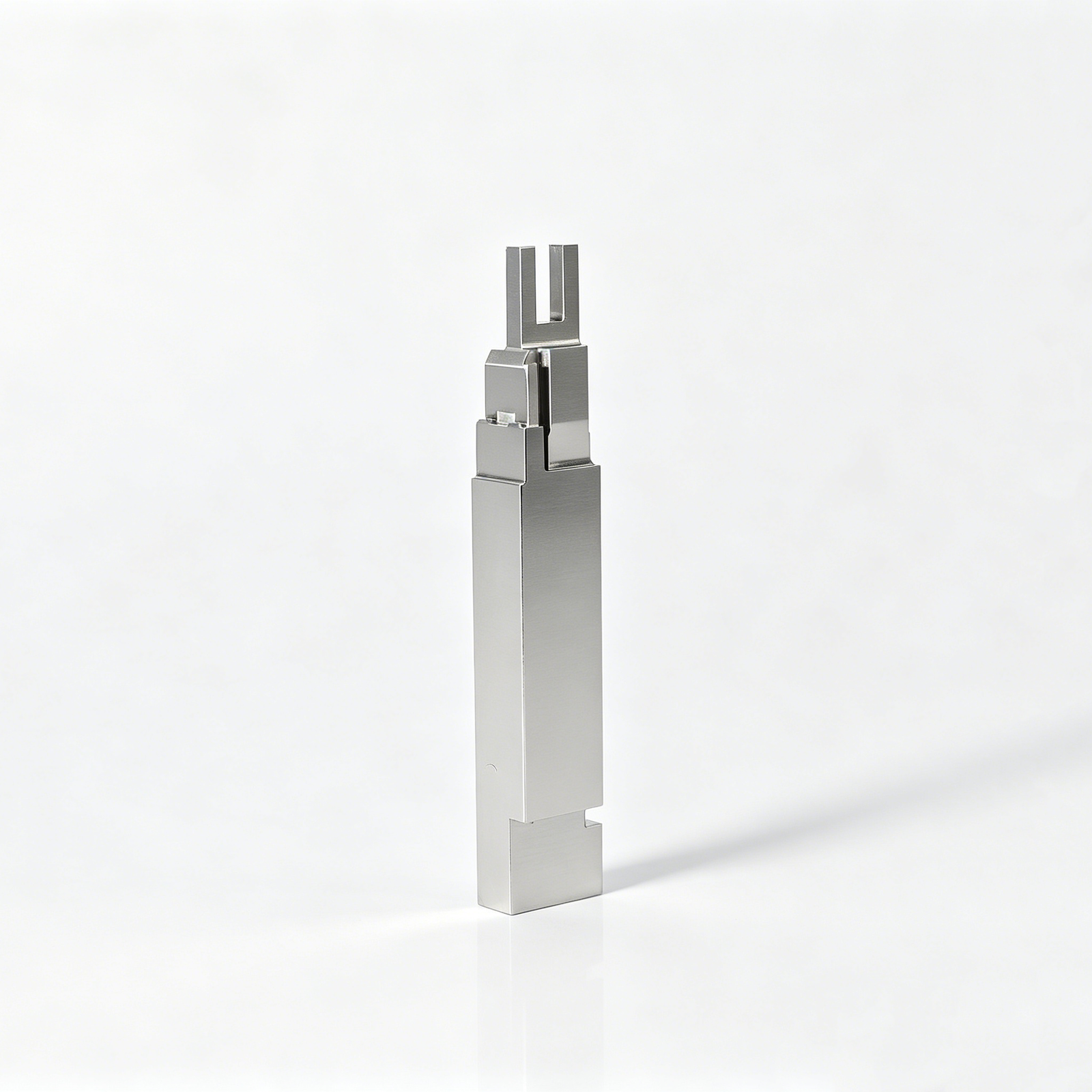
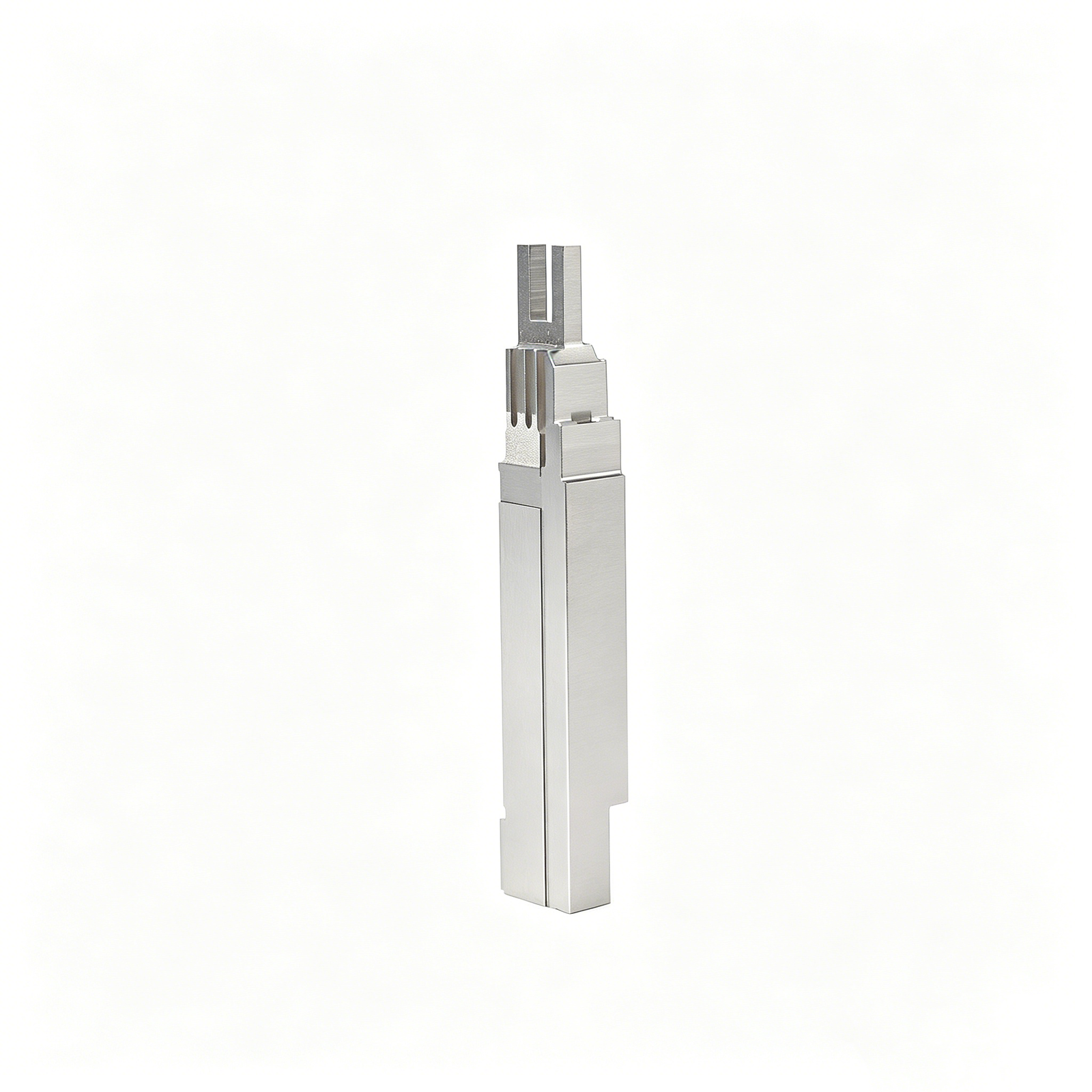
Custom Forked Connector Core Insert
A forked core insert with shoulders and reliefs. Discuss the fork opening, locating surfaces and support during manufacture.
View Component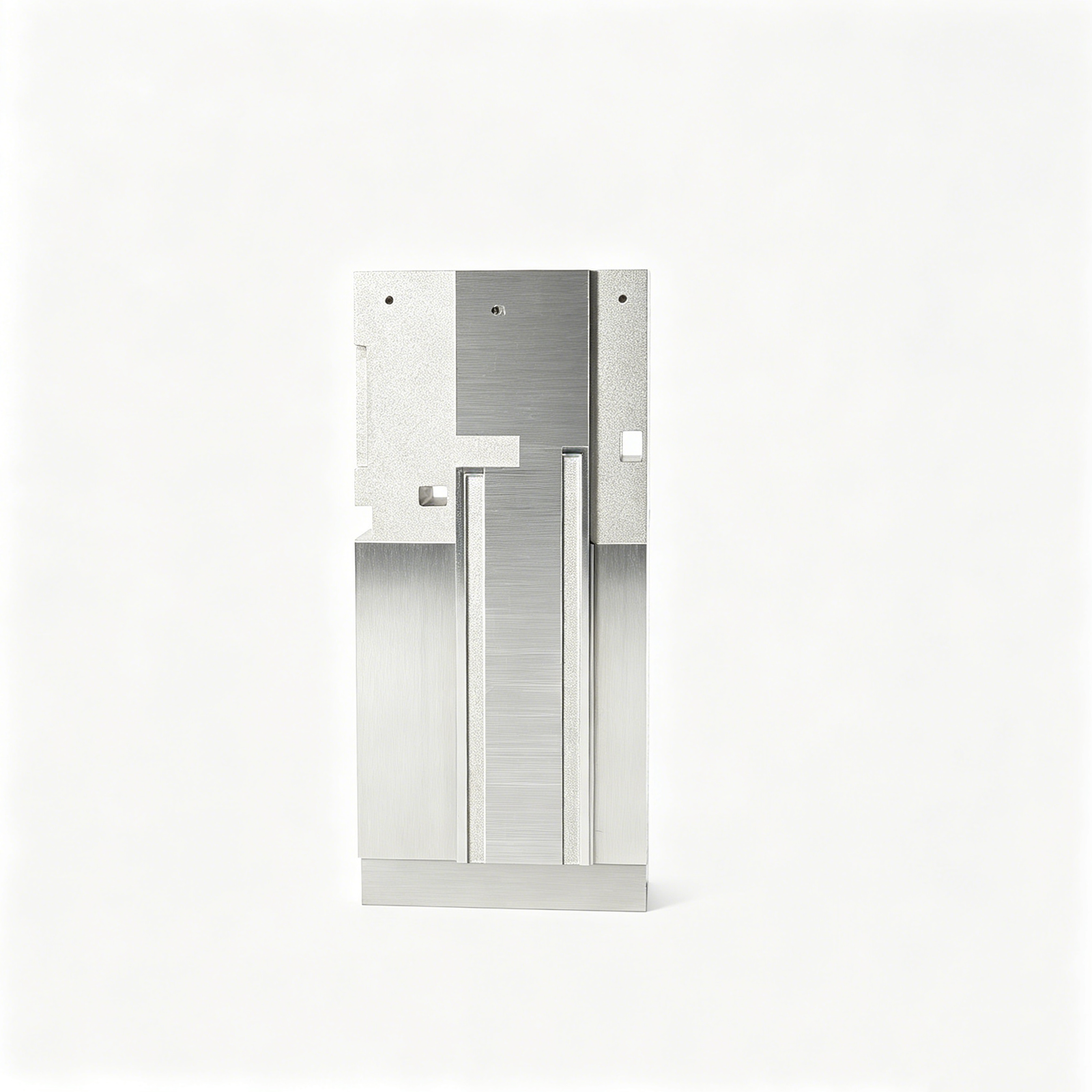
Custom Precision Connector Cavity Block
A cavity block with recessed faces, slots and holes. Identify the functional cavity surfaces and assembly datums.
View ComponentWhat the Images Show — and What Your Drawing Must Define
Start with visible part geometry
Our catalogue examples show stepped shafts, pockets, ribs and cavity details. Compare these features with your drawing, then follow the product link for context. A photograph cannot establish material grade or a numerical tolerance.
Link the drawing to acceptance
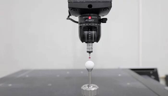
Ask which drawing revision, critical features and records will govern release. Technical reference: the pictured CMM probe illustrates a measurement concept, not SUUXIANG-owned equipment or a completed order.
Before You Order CNC and Mold Component Manufacturing
Choose a route by geometry, not by a catalogue photograph. Round parts, parts with pockets or flats, and mold cores or cavities need different reviews. SUUXIANG is the website brand of Dongguan SuuXiang Precision Mold Co., Ltd., founded in 2010 in Chang’an, Dongguan. The photographs below come from the company’s product catalogue; they are not customer case studies or inspection certificates.
Match the component family
Show the assembly interface or mold position, and identify whether the request concerns a new part, replacement component or repeat order.
Make quotations comparable
Use one drawing revision and separate prototype, initial-order and expected repeat quantities. List required finishing and acceptance documents.
Separate examples from commitments
Catalogue geometry and technical illustrations help explain a request. Material, tolerances, manufacturing route, price and schedule need written project confirmation.
Related Paths for Drawing-Driven Precision Manufacturing
Start with the drawing, CTQ dimensions, material, finish and documentation requirements to define a practical manufacturing and inspection route.
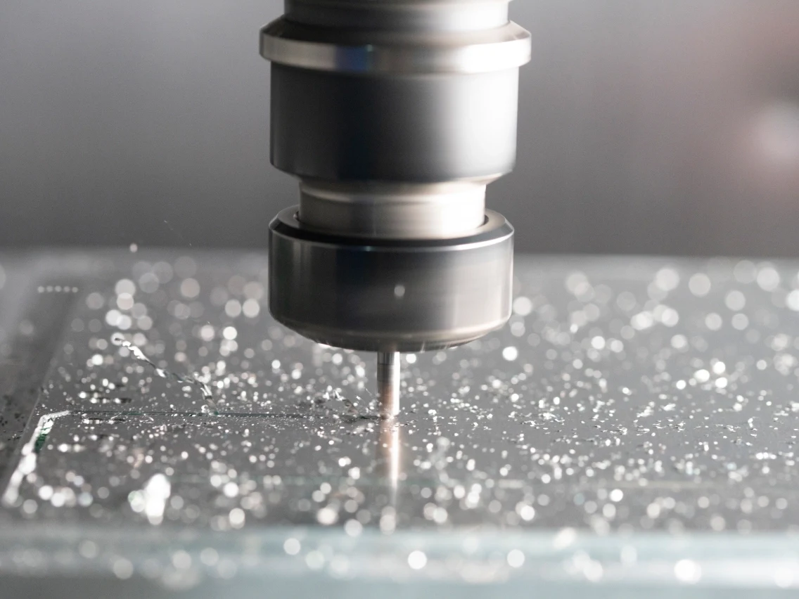
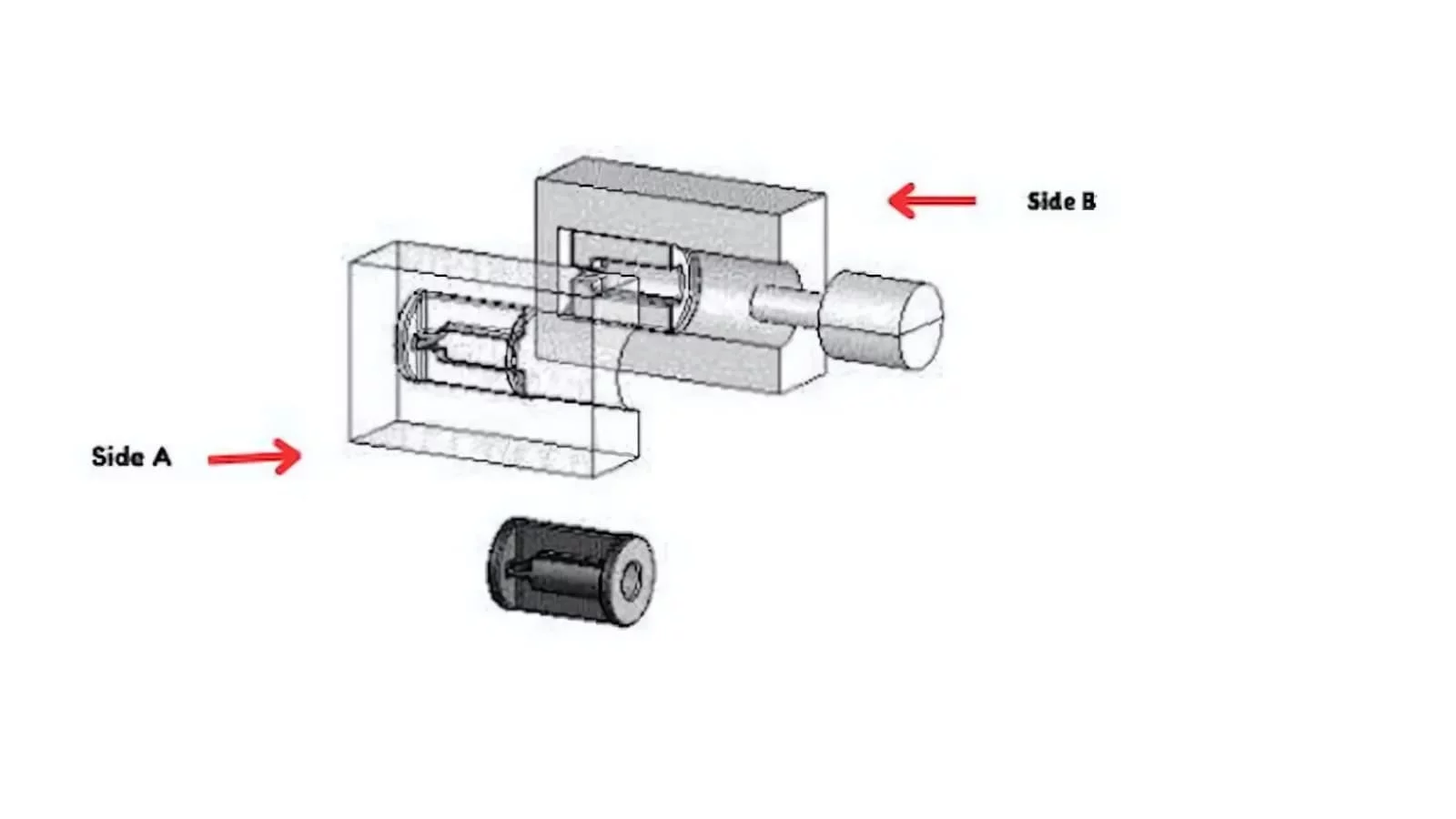
Precision Mold Components
Review cores, cavities, inserts and other drawing-defined mold components.
Explore Mold Parts
Custom Machined Parts
Browse custom machined part families and their engineering considerations.
Explore Parts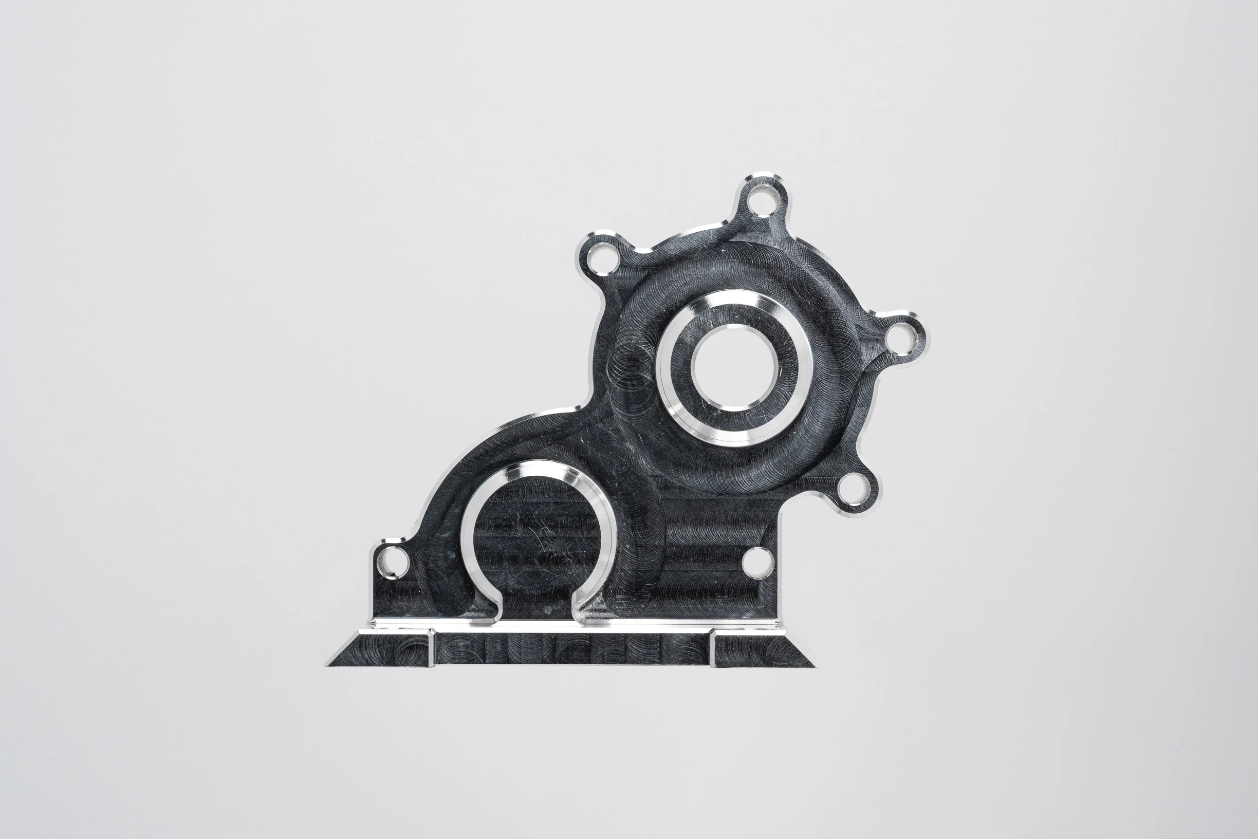
Surface Finishes and Heat Treatment
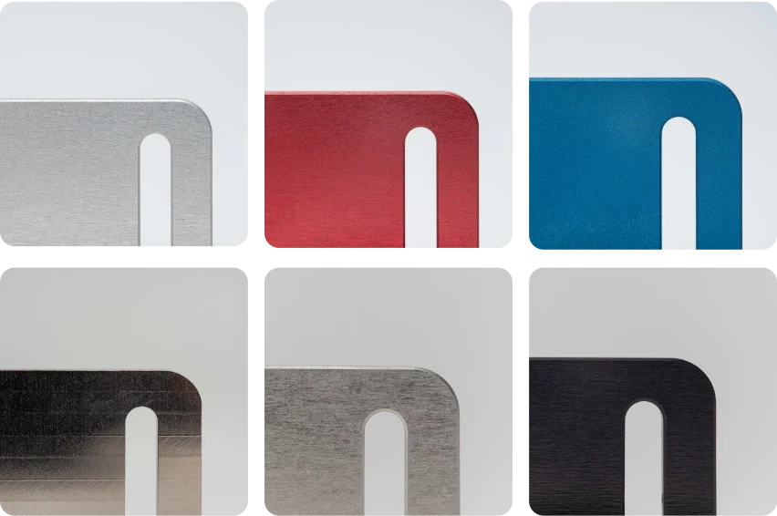
Review finishing and heat-treatment choices against part requirements.
Explore Finishes
Industries and Applications
Navigate manufacturing considerations by industrial application.
Explore Industries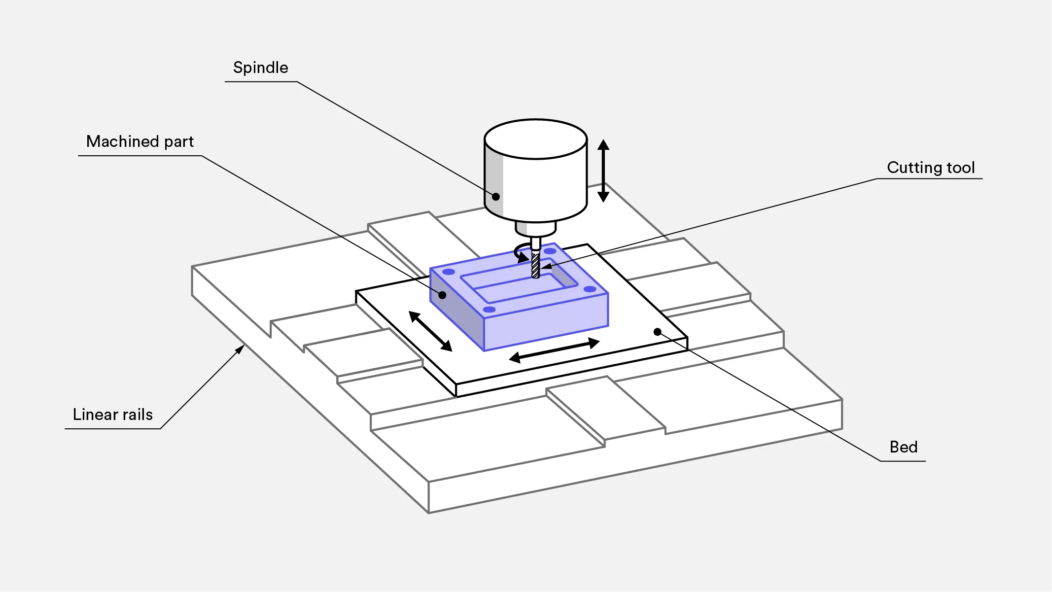
Engineering Knowledge Center
Read CNC, mold-design and inspection guidance organized by topic.
Explore Knowledge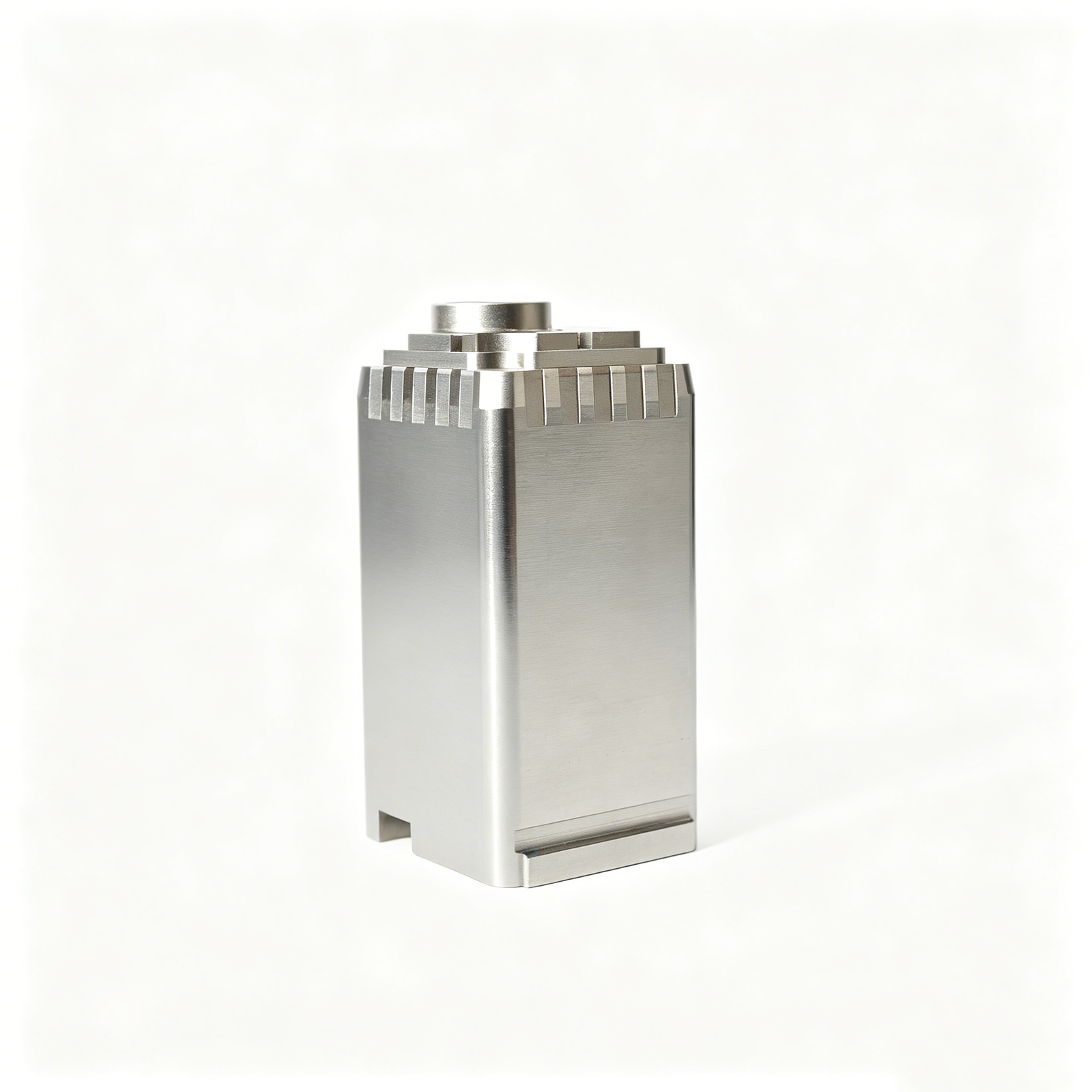
Manufacturing Case Studies
Read illustrative engineering scenarios; these are not customer case claims.
Explore ScenariosQuality Assurance
Plan drawing review, critical features, measurement and documentation.
Review Quality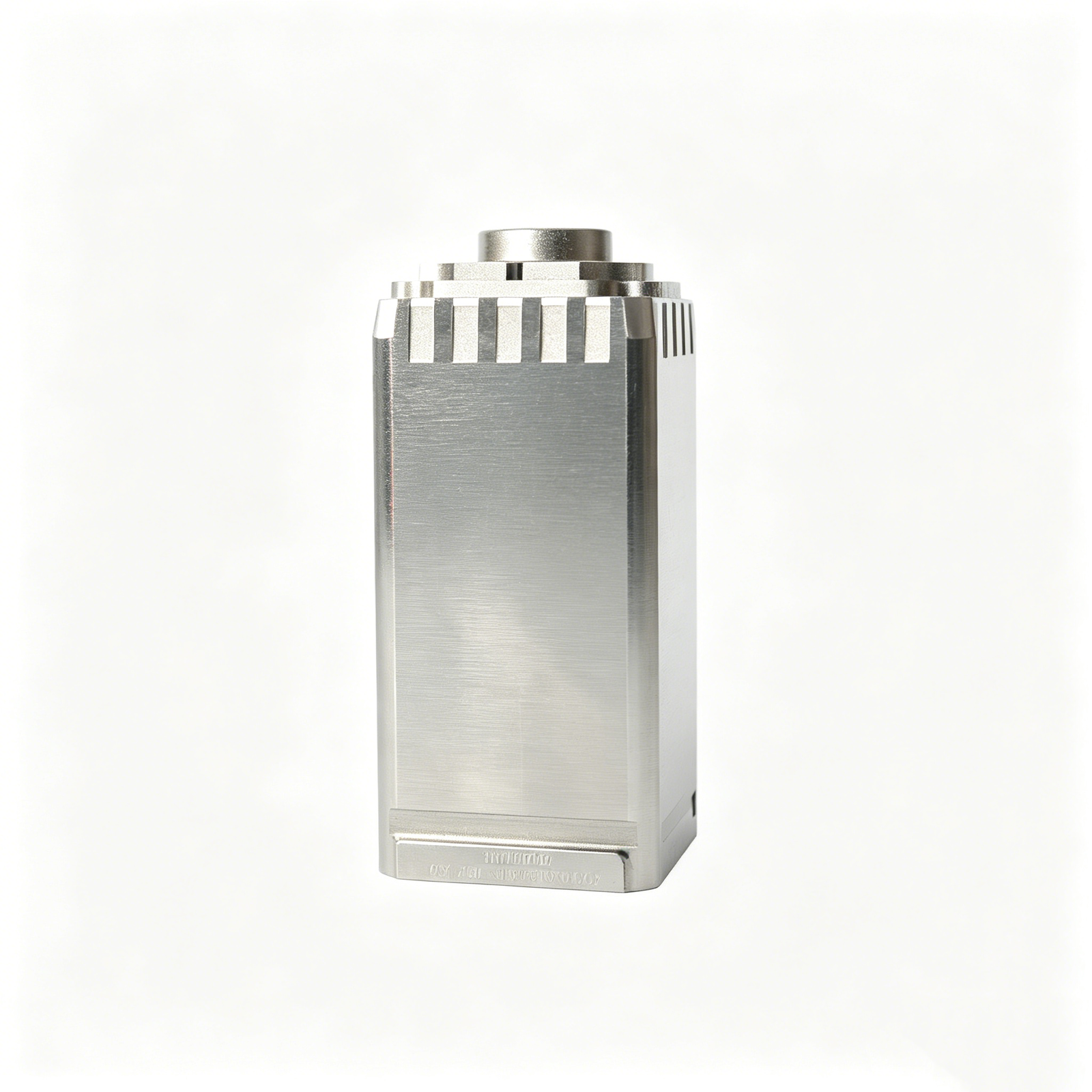

Request a Manufacturing Quote
Send project requirements for a manufacturing quotation.
Request a Quote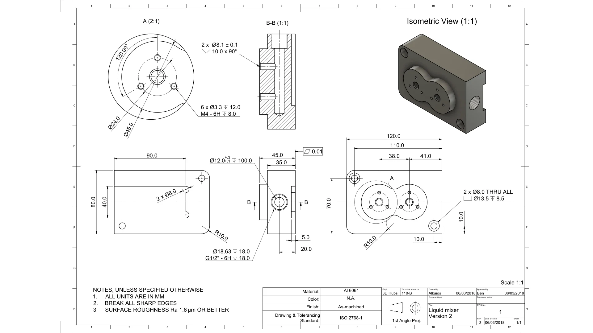
Upload a Drawing for Review
Share a drawing so the team can review manufacturability and requirements.
Upload a DrawingPrecision CNC Machining Materials for Function and Control
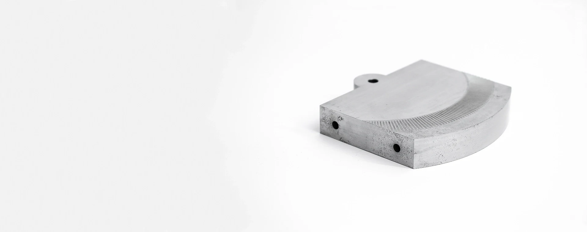
Tool Steels
Selected for mold cores, cavity inserts, stamping-die components and wear-critical tooling. Grade, heat-treatment condition, machining allowance and finishing route should be confirmed from the drawing and application requirements.
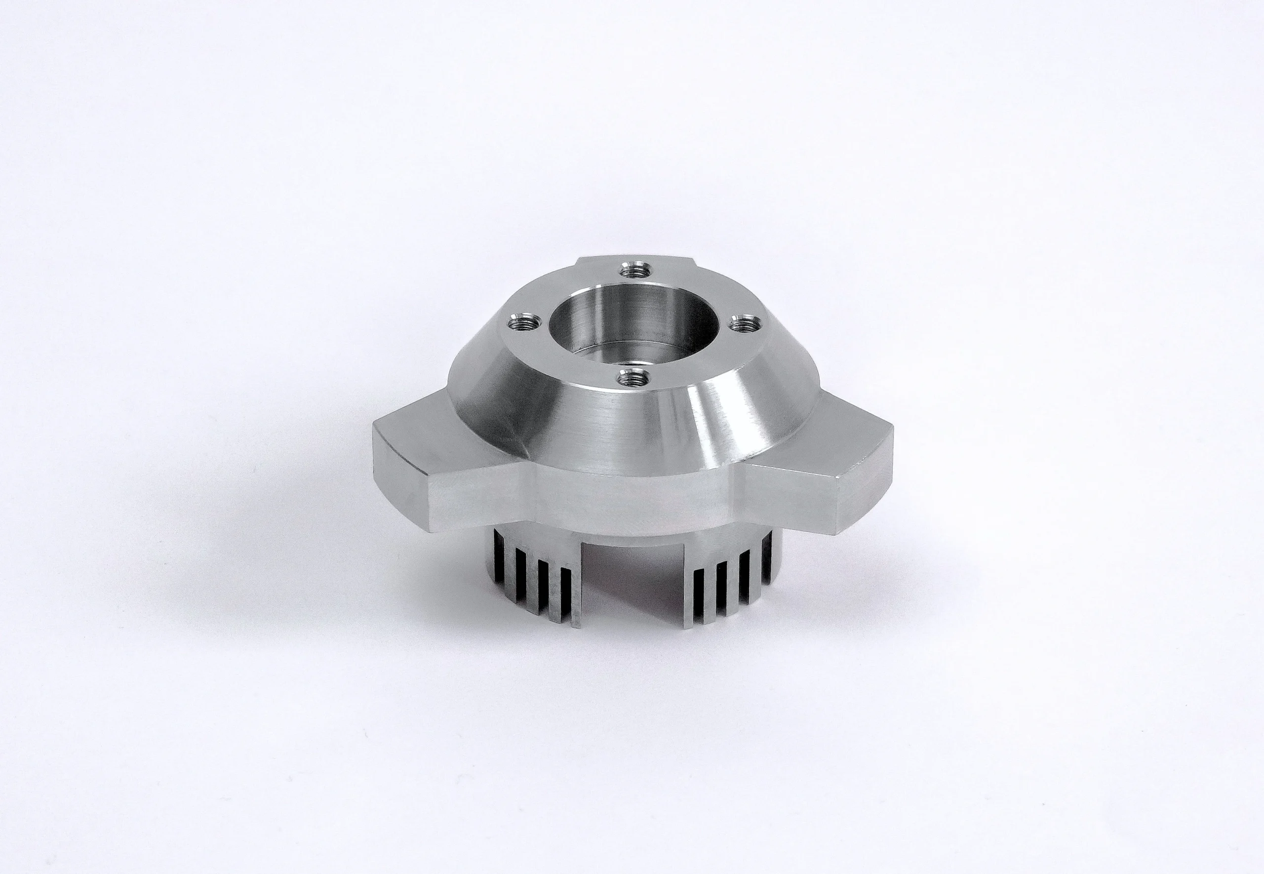
Stainless Steels
Used where corrosion resistance, strength or clean-service performance matters in custom parts and tooling components. Material grade, hardness condition, surface requirement and inspection priorities guide the machining and finishing plan.
Aluminum Alloys
A practical option for lightweight fixtures, prototype parts and selected tooling applications. Alloy choice affects machinability, stability, anodizing compatibility and thread strength, so functional loads and surface requirements should accompany the RFQ.
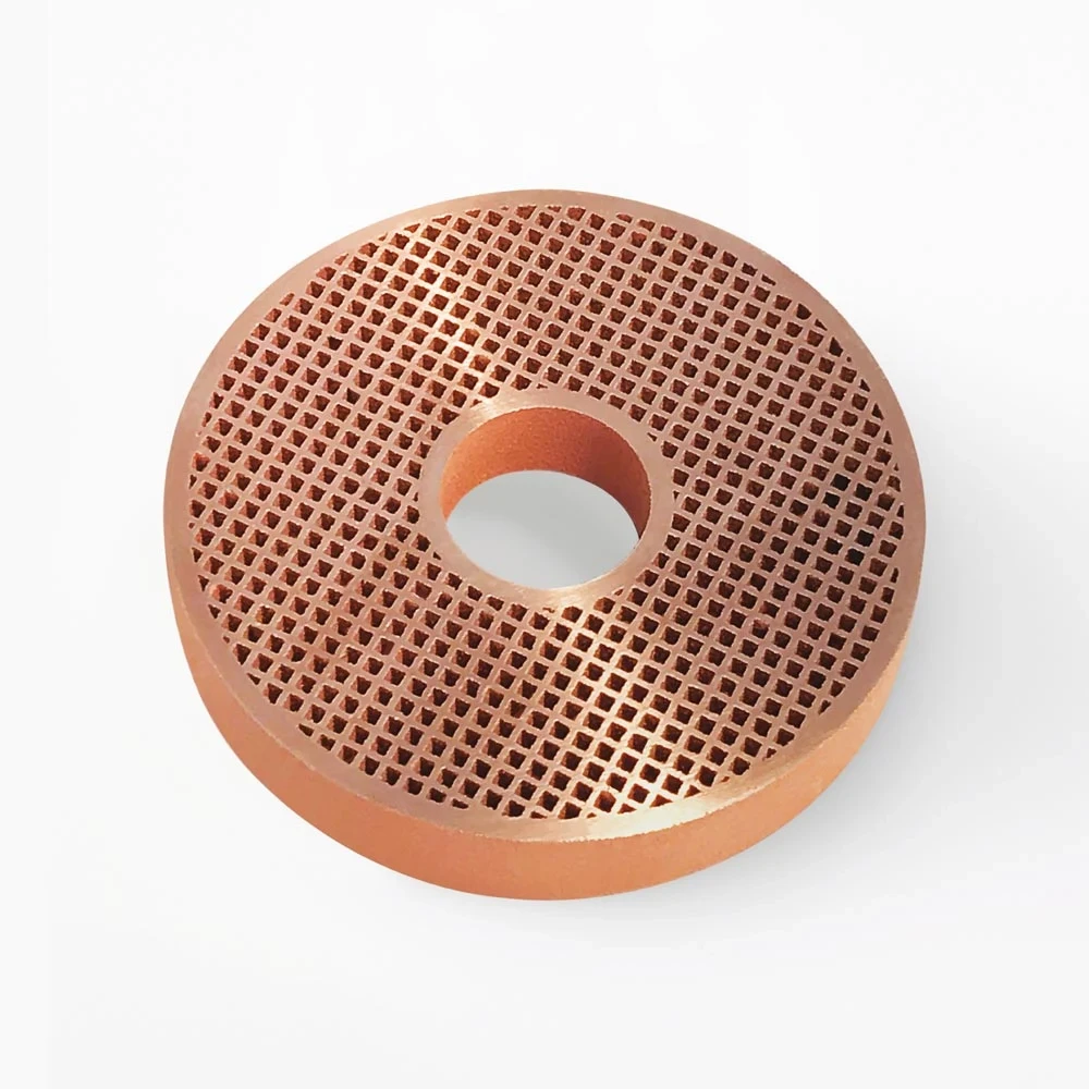
Copper Alloys
Considered for electrically conductive or thermally responsive components, including specialized tooling details. Alloy selection must account for conductivity needs, machining behavior, dimensional priorities and any mating-component or finishing constraints.
Engineering Plastics
Applicable to selected low-friction, insulating or chemically resistant components where dimensional behavior supports the application. Grade, moisture exposure, thermal conditions, tolerances and inspection method require review before machining is planned.
Precision CNC Machining, EDM, Grinding and Fitting
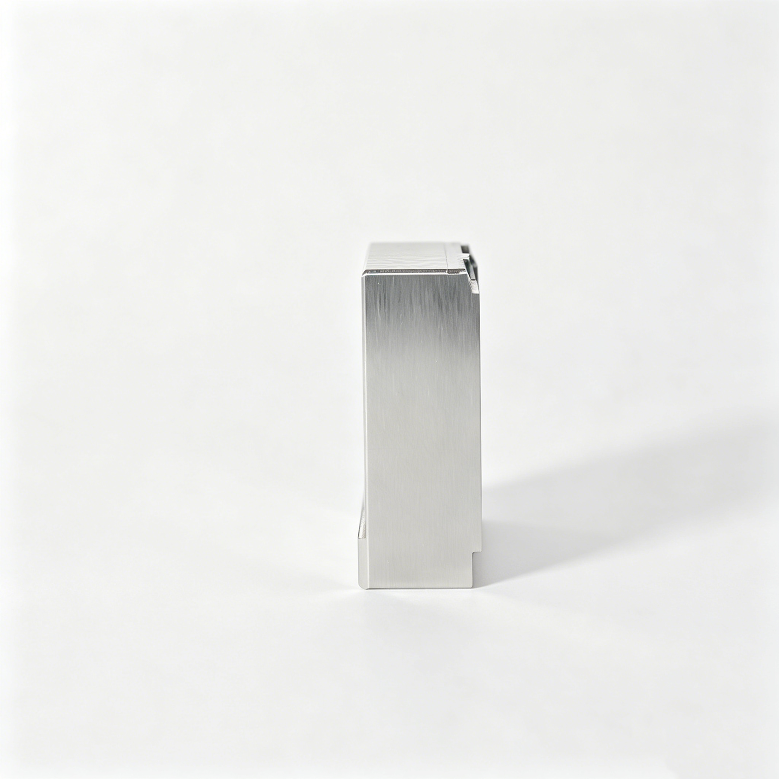
CNC Milling Services
CNC milling removes material from prismatic parts, pockets, contours and mold inserts. Tool access, datum locations and machining allowance are reviewed early to support stable features, controlled surfaces and efficient downstream EDM or grinding.
CNC Turning Services
CNC turning produces concentric diameters, bores, threads and rotational profiles for pins, sleeves and custom components. The route considers datum relationships, wall thickness and subsequent finishing requirements so functional interfaces remain practical to inspect.
5-Axis Machining
Multi-axis machining reaches angled, compound and contoured features with fewer setups where geometry supports it. Setup strategy and tool approach are planned around critical dimensions, helping reduce repositioning risk on complex mold and connector-tooling components.
Wire EDM Services
Wire EDM cuts precise profiles, narrow slots and hardened features where conventional tool access is limited. Wire path, start holes, corner conditions and finish requirements are reviewed with the drawing to protect functional geometry and mating relationships.
Sinker EDM Services
Sinker EDM forms internal details, deep cavities and sharp-featured geometry using planned electrodes. Electrode strategy, spark allowance and finishing expectations are aligned before machining, particularly where cavity shape or hardened material constrains milling access.
Precision CNC Machining Component Features and Identification
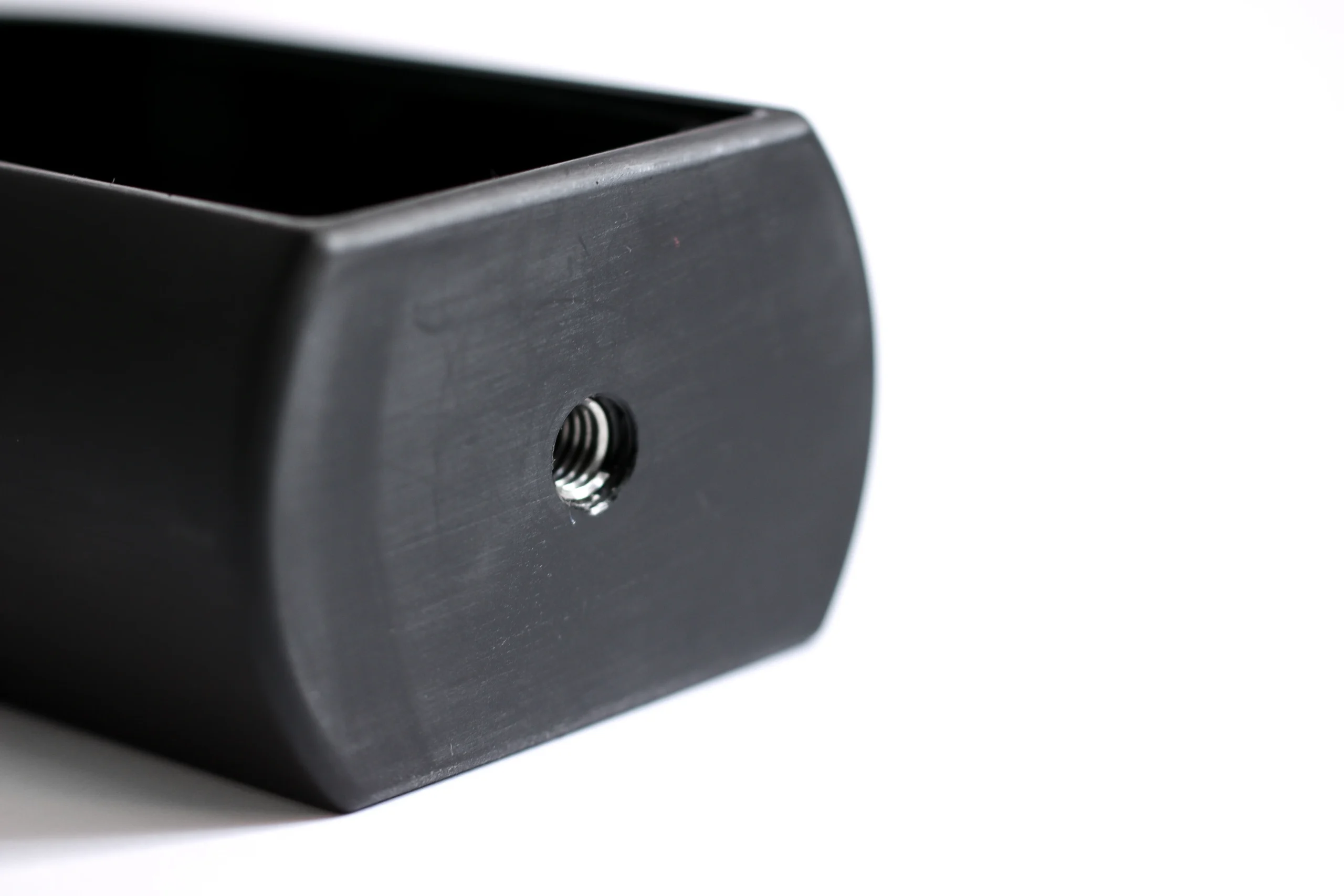
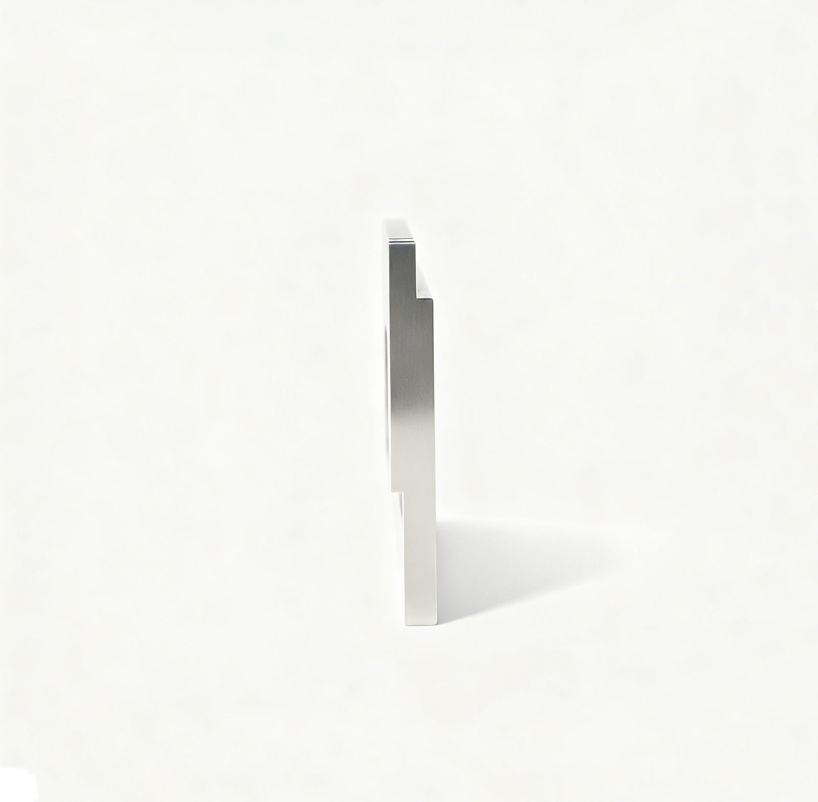
Fastener Provisions
Threaded holes, dowel locations, screw clearances and captive-fastener features can be machined to the approved drawing, with datum relationships and assembly access reviewed before production begins.
Guide Elements
Guide pins, bushings, locating features and wear surfaces can be supplied or accommodated where the order defines mating conditions, material requirements, fitting expectations and inspection priorities.
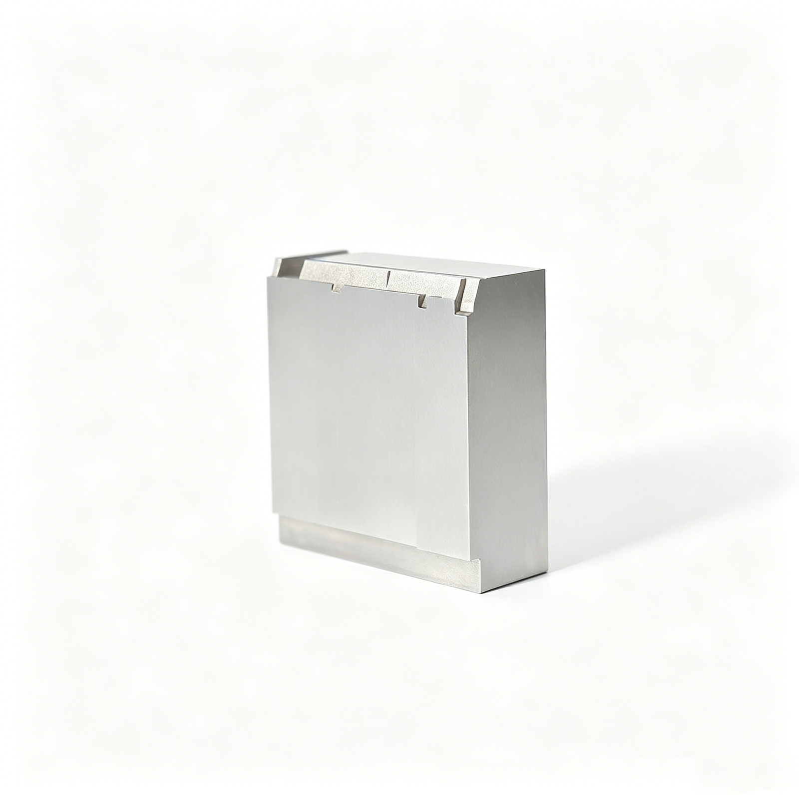
Precision Inserts
Replaceable cores, cavity inserts and custom insert interfaces support mold maintenance and design changes. SUUXIANG reviews seating surfaces, retention method, machining allowance and critical dimensions from the drawing.
Part Identification
Part numbers, revision marks, cavity identification and controlled labels can be considered when requested. The marking method, location and legibility requirements should be defined with the applicable drawing documentation.
Protective Packing
Protective packing can be planned around finished surfaces, sharp edges, corrosion risk, matched sets and shipment documentation. Provide handling, separation and labeling requirements with the RFQ for review.
About SUUXIANG Precision Manufacturing
SUUXIANG is the public brand of Dongguan SuuXiang Precision Mold Co., Ltd., founded in 2010 in Chang’an, Dongguan. XiaoCheng Huang is the founder and legal representative. The company works with engineering, tooling, procurement and quality teams on drawing-defined precision components.
The work combines CNC machining with precision mold components, connector tooling, EDM, grinding, fitting and inspection planning. A process route is selected around the actual geometry, material state, datum scheme, critical features and the documents required by the order.
Visitors should use the representative part photos to understand part families, not to infer an exact grade, tolerance or measured result. For a technical discussion, prepare the current drawing and model, quantity, material, finish, CTQs, inspection scope and target date.
Precision CNC Machining: From Drawing Review to Shipment
A drawing-driven workflow that aligns manufacturability, critical dimensions, process routing, inspection requirements, and delivery coordination before production begins.
Review the RFQ Package
We review drawings, models, quantities, materials, finishes, application context, target dates, and requested inspection documentation to establish a technically complete starting point.
Confirm DFM and CTQs
The team clarifies datums, critical-to-quality dimensions, tolerance stacks, machining access, surface requirements, and revision status before committing to a process route.
Plan Material and Processes
Material condition, heat-treatment sequence, machining allowance, EDM strategy, grinding stock, tooling needs, and fitting requirements are organized around the approved drawing.
Machine Critical Part Features
CNC milling, turning, multi-axis machining, EDM, grinding, and fitting are combined as needed to produce the specified part or mold-component geometry.
Inspect Against Requirements
Inspection methods and reporting follow the verified plan, focusing on specified dimensions, datums, surface priorities, and documentation required for the order.
Coordinate Packing and Delivery
Parts are packed according to project requirements, while final revision information, inspection records, and delivery coordination remain visible for repeat-order control.
Agree the Evidence Required for Your Order
Request records that match the actual drawing and acceptance scope. A technical reference image or blank template is not a certificate or completed report.
Dimensional record
Specify feature references, drawing revision, nominal requirements, measured results and sampling or full-check scope. Agree the format and suitable method.
Material and process records
List the material, heat-treatment or finishing documents required for acceptance. Confirm availability and included scope in the quotation; do not assume every document is supplied.
Release and changes
Identify who approves deviations, drawing changes and first-article results. Link the agreed records to the part identity and applicable order rather than a generic quality statement.
CNC and Mold Component Manufacturing — Practical Buyer Questions
Direct answers for preparing the RFQ and defining acceptance. Project-specific commitments belong in the quotation and agreed order.
How do I choose between CNC parts and mold components?
What should a first RFQ contain?
Does a displayed part prove the same tolerance on my part?
Can I request production or quality evidence?
Precision Parts RFQ
A practical decision framework for a drawing-defined precision part, from the first drawing review to documented acceptance.
1. Define the part and its function
Record the part family, assembly role and functional interfaces before choosing a machining method; the same visible shape may serve very different loads or fits.
2. Control the current drawing revision
Identify which PDF, CAD model and revision note form the controlling package; conflicting callouts must be resolved before a quote becomes a production instruction.
3. Separate critical from noncritical dimensions
Highlight fits, true positions, flatness and surfaces that change assembly behavior, then separate them from general dimensions that can use a different inspection frequency.
4. Choose a realistic process route
A pocket, fine rib or deep bore may call for CNC, EDM or grinding in sequence; tool reach and heat-treatment state can change both cost and achievable finish.
5. Specify material and heat treatment
State the exact grade and supply condition rather than naming only steel or aluminum; certificates and hardness requirements belong in the same specification package.
6. Plan measurement before production
Select CMM, optical or manual methods according to feature geometry and access; a numerical tolerance is incomplete without a realistic way to verify it.
7. Compare quotations on equal scope
Compare suppliers on included operations, secondary treatment, inspection evidence, sample approval, packing and revision ownership rather than unit price alone.
8. Prepare the next RFQ
A useful RFQ includes 2D and 3D files, quantities, material, treatment, CTQs, finish, documentation needs, target date and destination.
Review Parts and Prepare Your Drawing Package
Compare the representative components, then gather the current drawing revision, material, quantity, CTQs, finish, inspection scope and target date for a project discussion.