
Antenna Housing CNC Parts, Planned From Your Drawing
SUUXIANG reviews antenna housing CNC parts for DFM, critical dimensions, process routing, and inspection requirements before production planning.
Representative CNC Parts for Antenna Housing Development





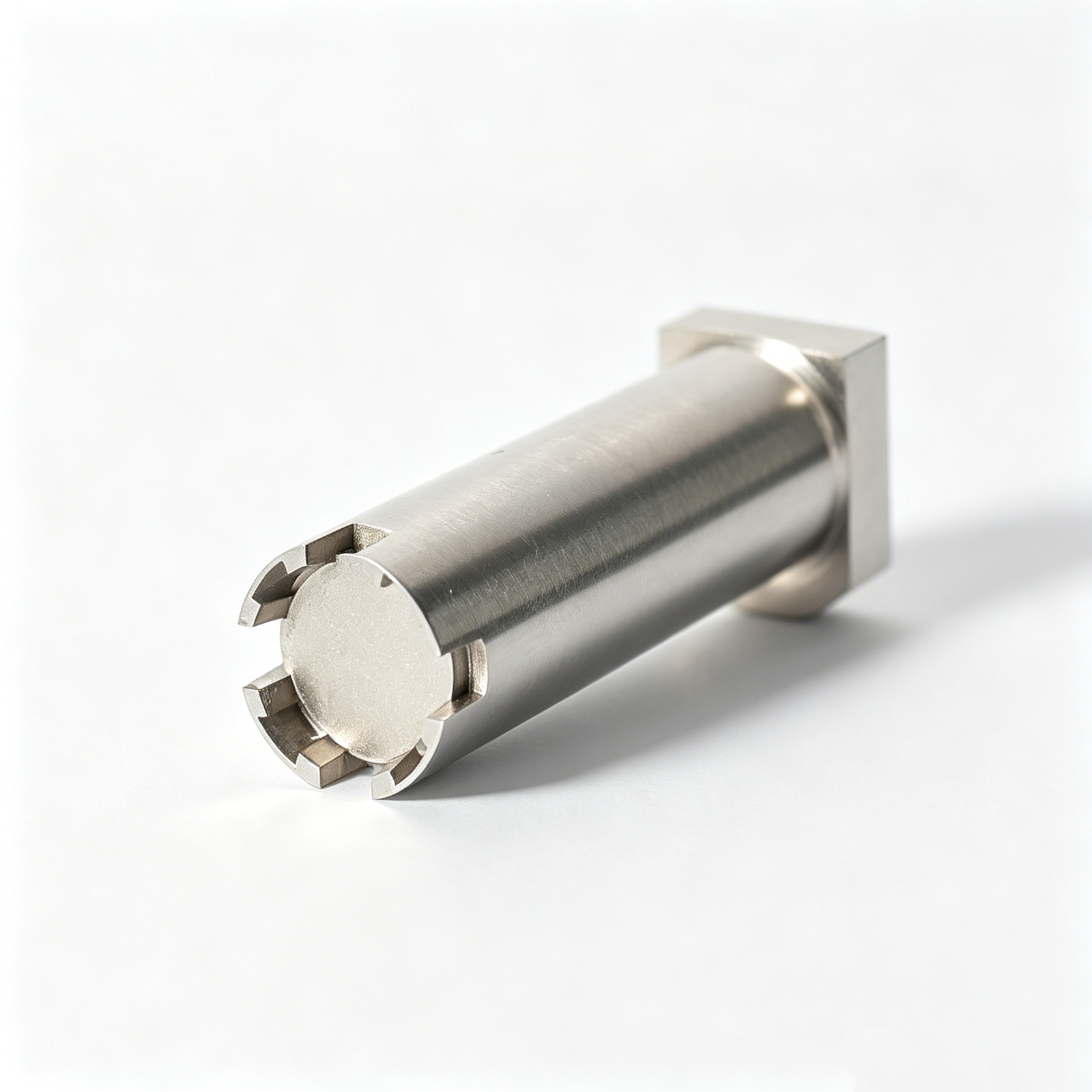


Related Drawing-Based Parts and Quotation




Antenna Housing CNC Parts: Engineering Advantages
A drawing-led workflow that identifies manufacturing risks before production commitments are made.
Drawing-Led DFM Review
Review drawings and models for feature access, wall conditions, tolerances, materials, and process risks before quotation or production planning begins.
Datum Strategy First
Align machining and inspection planning around functional datums, mating relationships, and critical dimensions to help control tolerance stack across operations.
Integrated Process Routing
Plan CNC milling, turning, EDM, grinding, and fitting as required by geometry, material condition, surface requirements, and inspection priorities.
Critical-Dimension Planning
Identify features requiring focused process control, then define practical measurement methods and reporting expectations with the customer before machining.
Revision-Controlled Communication
Keep drawing revisions, technical questions, inspection requirements, and delivery information visible so manufacturing decisions remain traceable throughout the project.
Inspection Plan Alignment
Match final inspection documentation to the agreed order requirements, critical features, and verified measurement plan for antenna housing CNC parts.
Antenna Housing Parts and Tooling Families
Drawing-driven CNC, mold, connector and die components for communication-equipment programs, reviewed against critical dimensions, materials and inspection requirements.

Precision CNC Machining Services
Precision CNC machining services for drawing-based antenna housings, brackets, interfaces and custom communication-equipment parts. Process planning considers material, datum structure, critical dimensions, machining access, surface requirements and the inspection evidence required before production is released.
Upload a Drawing
CNC Milling Services
Custom CNC milling services for prismatic housings, mounting features, RF-related mechanical interfaces and mold components. Drawing review identifies tool access, pocket geometry, wall conditions, datum references and features that may require EDM, grinding or a revised machining sequence.
Upload a Drawing
CNC Turning
Precision CNC turning services for cylindrical parts such as sleeves, bushings, threaded interfaces, pins and rotational housing features. Quotations should define material, concentricity and runout expectations, datum references, surface requirements and any secondary milling, grinding or inspection steps.
Upload a Drawing
5-Axis Machining
5-axis CNC machining supports complex surfaces, angled features and multi-face parts where fewer setups can protect datum relationships. Feasibility depends on tool reach, fixture strategy, material condition, critical tolerances and the inspection method specified for the finished component.
Upload a Drawing
Swiss & Micro Machining
Swiss machining and micro machining support small, detailed turned components used in connector, antenna and tooling assemblies. Review is based on part geometry, material, slenderness, critical features, burr requirements, secondary operations and the measurement approach appropriate to the drawing.
Upload a Drawing
Wire EDM Services & Sinker EDM Services
Wire EDM and sinker EDM services address hard materials, narrow slots, internal profiles, sharp internal geometry and features with limited milling access. Electrode strategy, wire path, flushing, stock condition and subsequent finishing requirements should be agreed during drawing review.
Upload a Drawing
Precision Grinding
Precision surface and profile grinding is used when flatness, parallelism, profile control or controlled finishing stock is critical. The process route should define heat-treatment sequence, grinding allowance, datum control, surface requirements and the planned inspection method.
Upload a Drawing
Mold Core & Cavity Inserts
Precision mold core and cavity inserts are configurable components built from approved drawings, material and heat-treatment requirements. Manufacturing planning considers shutoff geometry, cooling or vent features, EDM access, polishing needs, fitting interfaces and critical dimensions before release.
Upload a Drawing
Ejector & Ejection Components
Ejector pins, sleeves and ejection components are produced to drawing-defined diameters, fits, lengths and working conditions. Material, hardness, surface finish, clearance relationships and mating-component information are important inputs for selecting a suitable manufacturing and inspection route.
Upload a Drawing
Core Pins, Guide & Locating Components
Core pins, guide pins and locating components support repeatable alignment and controlled mold movement. A drawing review should establish datum relationships, fit class, hardness and finish requirements, straightness or concentricity needs, and how critical dimensions will be verified.
Upload a Drawing
Slides, Lifters, Gates & Mold Accessories
Mold slides, lifters, gates and accessories are configured around mold motion, parting-line conditions, material flow and mating interfaces. SUUXIANG reviews machining access, EDM requirements, wear surfaces, heat-treatment sequence, fitting allowances and inspection priorities from the supplied design.
Upload a Drawing
Connector Mold Components
Precision connector mold components support fine-pitch, multi-cavity and high-repeatability tooling requirements. Component planning evaluates micro features, pin and insert geometry, datum strategy, EDM or grinding needs, material condition and dimensional evidence required for assembly and validation.
Upload a Drawing
Stamping Die Components
Precision stamping die components include drawing-based punches, dies, guide elements and custom formed or machined parts. Manufacturing decisions depend on material, hardness, cutting geometry, clearance relationships, grind stock, wire-EDM paths and the inspection plan for functional dimensions.
Upload a Drawing
Injection, MIM, CIM & Overmolding Tooling
Injection, MIM, CIM and overmolding tooling components are evaluated within verified production scope. Drawings should identify molded material context, parting and shutoff features, cavity or core requirements, insert interfaces, heat-treatment needs and any dimensional priorities affecting tool performance.
Upload a Drawing
Machining Materials
CNC machining materials are selected from the customer’s drawing and application requirements, not assumed from a generic list. RFQ information should state material grade, condition, traceability needs, corrosion considerations, heat treatment and any restrictions that affect machining or inspection.
Upload a Drawing
Surface Finishes & Heat Treatment
Surface finishing and heat treatment are planned as part of the component route because they can affect dimensions, surface condition and final inspection. Specify coating or finish requirements, hardness targets, masking needs, post-treatment stock and any documentation required with the order.
Upload a Drawing
Quality, Metrology & Documentation
Precision inspection, metrology and quality documentation are aligned to the drawing’s critical dimensions, datums and reporting needs. Before production, define measurement methods, sampling or full-inspection expectations, revision status, material records and the documentation required for acceptance.
Upload a Drawing
Prototyping & Low-Volume Production
Rapid prototyping and low-volume manufacturing support drawing-based evaluation parts, bridge quantities and controlled production releases. Submit the 2D drawing, 3D model when available, material, quantity, delivery target, critical features and inspection requirements so process feasibility can be assessed.
Upload a DrawingMaterials for Antenna Housing CNC Parts

6061 Aluminum
A lightweight, readily machinable aluminum option for many structural antenna housings and covers. Its balanced strength and stable cutting behavior suit milled pockets, mounting faces and cosmetic finishing, subject to alloy, temper and coating verification.

7075 Aluminum
A higher-strength aluminum choice where loading, stiffness or compact wall sections influence the housing design. It machines differently from 6061, so tool access, distortion risk, thread engagement and finishing requirements should be reviewed from the drawing.

Stainless Steel
A dense, durable material for antenna components exposed to wear, demanding mounting conditions or corrosive environments. Its tougher cutting character can affect cycle planning, tool selection, internal-feature access and the specified surface condition.

Brass Alloys
A comparatively free-machining metal often considered for conductive inserts, threaded features and precision mating details. Its smooth cutting response supports fine features, while the exact alloy, electrical requirements and plating or finish callouts need confirmation.

Engineering Plastics
A lower-weight, electrically insulating option for selected covers, isolators or non-load-bearing antenna housing features. Material grade influences stiffness, moisture response, thermal behavior and clamping strategy, requiring drawing and application review before production.
Antenna Housing CNC Parts: Process Routes for Complex Features

CNC Milling
CNC milling forms housing profiles, pockets, mounting faces, and interface features from the drawing. Tool selection and fixture strategy are reviewed to protect datum relationships, surface access, and repeatable machining results.

CNC Turning
CNC turning supports rotational features such as bores, threads, shoulders, and concentric interfaces. It can establish controlled relationships between cylindrical diameters and seating faces when the component geometry suits a turning route.


Wire EDM
Wire EDM creates precise through profiles, narrow slots, and intricate contours where cutting-tool access is limited. Wire path, start-hole placement, corner conditions, and finish requirements should be defined during drawing review.

Sinker EDM
Sinker EDM forms deep cavities, sharp internal details, and complex enclosed features using planned electrodes. Electrode strategy, spark access, material condition, and downstream finishing requirements guide this process choice.

Precision Grinding
Precision grinding refines selected faces, diameters, and datum surfaces after machining or heat treatment. Grinding stock, flatness or parallelism priorities, surface requirements, and inspection method should be agreed before release.
Functional Hardware for Antenna Housing CNC Parts

Threaded Inserts
Helical or press-fit inserts can support repeated assembly in specified housing locations. Provide the insert type, thread size, installation condition, pullout requirements, and any finish restrictions for drawing review.

Captive Fasteners
Captive screws, standoffs, and specified fasteners help retain covers or internal assemblies. Define thread standard, head clearance, tightening access, mating material, and whether supplied hardware must be installed before final inspection.

Locating Features
Dowel holes, datum pads, alignment bosses, and keyed interfaces establish repeatable relationships between antenna housing CNC parts and mating components. Identify functional datums, positional tolerances, fit intent, and inspection references on the drawing.

Identification Labels
Part labels, laser-marking areas, and serialized identification zones can support assembly traceability. Specify content, location, character limits, contrast requirements, and any surfaces that must remain free from marking or coating.

Protective Treatments
Specified anodizing, conductive finishes, passivation, masking, or protective packaging can be reviewed against functional surfaces. Define finish callouts, masked zones, cosmetic priorities, electrical-contact areas, and handling requirements before process planning.
About SUUXIANG Precision Manufacturing
SUUXIANG is the international-facing brand of Dongguan SuuXiang Precision Mold Co., Ltd., established in 2010 in Chang’an Town, Dongguan, Guangdong, China. We help engineering, sourcing and quality teams turn controlled drawings and specifications into inspected custom CNC parts, precision mold components and connector-tooling work.
For antenna housing CNC parts and related precision components, our process planning can combine CNC milling and turning, multi-axis machining, EDM, precision grinding, fitting and inspection. Each route is defined around the drawing, functional features, material requirements, machining access, critical dimensions and applicable inspection expectations.
What distinguishes SUUXIANG is disciplined project communication before production commitments. We review DFM, datum strategy, tolerance stack, surface requirements, heat-treatment sequence and revision status so buyers can align the manufacturing route and inspection plan with their RFQ requirements.

How SUUXIANG Controls Antenna Housing CNC Parts
DFM Starts at the Datum
SUUXIANG reviews antenna housing CNC parts against the drawing, model, mating context and critical dimensions before production planning. The review clarifies datum relationships, tolerance stacks, tool access and surface priorities so the quoted route reflects the functional requirement.
- Identify functional datums and critical-to-quality features
- Review wall transitions, pockets, threads and mating interfaces
- Flag machining-access or tolerance-stack risks early
- Confirm material, quantity and inspection expectations

Plan CNC, EDM and Grinding
Complex geometry may require more than a single milling setup. SUUXIANG plans the appropriate sequence of CNC machining, wire EDM, sinker EDM and precision grinding, considering electrode strategy, wire paths, heat-treatment sequence and grinding stock before work begins.
- Match process route to feature geometry and access
- Reserve machining allowance for downstream grinding
- Define EDM strategy for narrow slots or internal details
- Coordinate heat treatment with final-size operations

Choose Inspection by Function
Inspection planning follows the drawing and verified quality requirements, rather than a generic checklist. SUUXIANG aligns measurement methods with critical dimensions, datum references, surface requirements and reporting needs, helping teams specify evidence that supports acceptance decisions.
- Link measurement points to drawing datums
- Prioritize critical interfaces and tolerance-sensitive features
- Agree required reports before production release
- Keep final documentation aligned with the order

Keep Revisions Visible
Antenna housing projects can change as interfaces, hardware or RF packaging develop. SUUXIANG keeps revision information, production status and delivery coordination visible throughout the project, reducing the risk of manufacturing to an outdated drawing or unconfirmed requirement.
- Confirm the released drawing and model revision
- Record changes affecting process or inspection planning
- Coordinate delivery against the agreed project requirements
- Use traceable communication for quality questions

Why Choose SUUXIANG for Antenna Housing CNC Parts
Compare a drawing-led manufacturing workflow with a quote-only sourcing approach before releasing antenna housing CNC parts.
← Swipe left or right to view →
Antenna Housing CNC Parts: Drawing to Inspection
A controlled, drawing-led workflow that keeps manufacturing decisions, revision status, and inspection expectations visible from RFQ through shipment coordination.
Review Drawings and Requirements
We review 2D drawings, 3D models, application context, quantity, material, critical dimensions, surface priorities, inspection needs, and target delivery requirements before quoting.
Plan Process and Material
The team confirms practical DFM points, datum strategy, machining access, material and heat-treatment sequence, machining allowance, and the proposed route for antenna housing cnc parts.
Machine Critical Housing Features
CNC milling, turning, multi-axis machining, or micro-machining are selected as required to establish housing geometry, interfaces, cavities, threaded features, and functional reference surfaces.
Apply EDM or Grinding
Where the drawing requires it, wire EDM, sinker EDM, or precision grinding addresses restricted features, fine profiles, hardened conditions, controlled stock removal, and surface requirements.
Fit, Inspect, Coordinate Shipment
Parts are fitted when applicable, inspected against the verified plan, documented to match the order, then prepared with revision-aware packing and delivery coordination.
Work With Our Antenna Housing CNC Parts Team
Move from drawing review to inspected delivery with clear technical inputs, documented decisions and revision-controlled communication.
Submit Your Drawing Package
Send 2D drawings, available 3D models, application context, quantity and target date so the team can understand the antenna housing CNC parts requirement.
Define Critical Requirements
Identify material, heat treatment, surface finish, critical dimensions, datum strategy, inspection reporting and mating-component constraints before process planning begins.
Review DFM and Quotation
Assess machining access, fixture needs, EDM or grinding requirements, tolerance risks and proposed scope; clarify open points before approving quotation or samples.
Approve Production Details
Confirm the controlled drawing revision, agreed material and quality plan, delivery requirements and any sample approval requirements before production is released.
Coordinate Inspection and Delivery
Receive progress communication aligned to the agreed plan, with final inspection documentation matched to the order and verified inspection requirements.
Antenna Housing CNC Parts: Certifications and Quality Documentation

Customer Feedback on Antenna Housing CNC Parts
Customer testimonial pending verification and publication approval. SUUXIANG will publish project feedback only when the customer, scope, outcome, and supporting inspection or delivery evidence can be confirmed.
Case example pending approval. Any published result will identify the relevant drawing revision, critical dimensions, inspection documentation, and delivery context so engineering teams can evaluate the outcome accurately.
Project feedback pending customer authorization. SUUXIANG does not present unverified performance claims; approved examples will describe the actual manufacturing route, revision coordination, and documented result.
Antenna Housing CNC Parts FAQ
Practical answers for engineering, sourcing, and quality teams preparing a drawing-based inquiry.
What files should I send for antenna housing CNC parts?
Can SUUXIANG quote low-volume antenna housing CNC parts or first samples?
How long does it take to make antenna housing CNC parts?
Which materials and heat treatments can be considered for an antenna housing?
Can you provide inspection reports for antenna housing CNC parts?
How are drawing revisions and IP handled during quotation and production?
Can antenna housing CNC parts include threaded inserts, hardware, or finishing?
What should I confirm for shipping and payment before placing an order?
The Complete Buyer’s Guide to antenna housing cnc parts
Use this practical framework to specify antenna housings, compare materials and finishes, evaluate CNC suppliers, control quality risk, and avoid costly DFM, sourcing, and launch mistakes.
1. What Are Antenna Housing CNC Parts?
2D drawings and 3D models define antenna housing CNC parts as machined enclosures, covers, bases, flanges, brackets, or structural interfaces made to customer requirements. They protect and locate the antenna assembly while controlling interfaces to connectors, fasteners, seals, cables, and mating equipment.
A housing can affect RF behavior indirectly through conductive contact paths, shielding continuity, connector alignment, antenna clearance, and unintended gaps near the radiating system. It may also provide an environmental barrier and thermal path, so datum locations, wall transitions, sealing lands, and mounting faces should be reviewed with the antenna and system design.
Custom CNC work is commonly justified by low-to-medium quantities, complex multi-face geometry, tight positional relationships, or late-stage revisions. A standard enclosure suits unconstrained packaging; casting or molding may become more suitable after geometry stabilizes and volume supports dedicated tooling, while fabricated sheet assemblies fit designs that do not require machined-interface precision.
2. Evolution of Antenna Housing Manufacturing
Before 5-axis CNC workflows became routine, antenna housings were often fabricated from sheet metal or made as relatively simple cast-and-machined structures, with generous access and fewer precision interfaces. As RF and communications assemblies became denser, machined faces, pockets, threaded features, and mating datums increasingly had to be controlled from the drawing.
By the 2000s, radar, satellite, and industrial antenna programs were placing more structure around waveguide paths, feed assemblies, seals, heat-transfer surfaces, and mounting interfaces. CNC milling made it practical to prototype these integrated geometries and to support lower-volume revisions without committing immediately to dedicated forming or casting tooling; antenna structures also commonly use aluminum for lightweight structural performance (https://us.arrk.com/signal-to-structure-cnc-machining-for-satellite-antennas).
For today’s antenna housing cnc parts, the sourcing implication is straightforward: the 2D drawing must identify functional datums, interface dimensions, sealing surfaces, thread specifications, finish requirements, and inspection points. Buyers should also provide the 3D model, mating-part context, environmental exposure, quantity, and revision status so the supplier can review tool access, workholding, and verification before release.
3. Types of Antenna Housing CNC Parts
A drawing may combine several antenna housing cnc parts, each with a different datum scheme and process route. Classify the functional interfaces before requesting a quotation.
Protective Enclosures
Two-piece enclosures protect internal electronics; pockets, gasket lands, and cable exits commonly require milling and drilling. Specify sealing faces, wall thickness, and cosmetic surfaces.
RF And Waveguide Housings
RF housings control internal geometry; deep cavities, narrow channels, and flange patterns may need multi-axis milling or EDM. Define interface datums, surface condition, and mating requirements.
Baseplates And Mounting Brackets
Baseplates locate assemblies; flat mounting planes, threaded holes, and stiffening ribs favor milling, drilling, and tapping. Identify flatness, positional tolerances, and installed hardware.
Connector-Interface Bodies
Connector bodies establish repeatable mating; bores, threads, and alignment features may require turning plus milling. Call out connector standard, concentricity, and burr-control expectations.
Covers And Heat Sinks
Finned covers dissipate heat and close assemblies; thin walls and narrow fin gaps drive tool-access limits. State fin geometry, contact-plane flatness, and finish requirements.
Prototype And Low-Volume Assemblies

Low-volume assemblies validate fit before release; mixed components may combine CNC, EDM, grinding, and fitting. Provide revision-controlled models, quantities, inspection priorities, and mating parts.
4. Materials for Antenna Housing CNC Parts
Material choice for antenna housing cnc parts is a system decision. RF behavior, sealing, structural loads, corrosion exposure, thermal path, finish, and compliance requirements must be reviewed together before release.
| Material Family | Best Fit | Key Tradeoff |
|---|---|---|
| Aluminum alloy | Lightweight outdoor enclosure | Needs corrosion and conductive-finish strategy |
| Stainless steel | Harsh or high-strength environment | Higher weight and machining effort |
| Brass or copper alloy | Conductive interfaces or shielding features | Higher mass and material cost |
| Engineering plastic | RF-transparent cover or insulation | Lower stiffness and thermal stability |
| Hybrid design | Sealing plus shielding requirements | More interfaces and assembly control |
Material Selection Matrix
Aluminum alloys often balance low mass, stiffness, machinability, heat spreading, and anodizing compatibility.
Stainless steel favors corrosion resistance and strength, while brass or copper alloys suit controlled conductive paths.
Application Tradeoffs
Engineering plastics reduce weight and can support RF-transparent covers, but their stiffness, thermal expansion, and environmental resistance require validation.
Hybrid housings combine a metal structural or shielding frame with polymer features where insulation, transparency, or sealing geometry matters.
Drawing Review Inputs
2D drawings should identify grounding interfaces, gasket lands, corrosion environment, and finish exclusions.
3D models should show mating parts, heat sources, antenna keep-out zones, and datum-based critical dimensions.
5. Customization and Surface Finish Options
A released 2D drawing should control cavity geometry, connector cutouts, threads, inserts, sealing lands, logos, and mating interfaces. For antenna housing cnc parts, define datums before cosmetic features so functional locations remain inspectable.
| Finish | Useful Attribute | Specify Before Production |
|---|---|---|
| Anodizing | Wear and corrosion resistance | Thickness, color, masked fits |
| Conductive conversion | Electrical continuity | Contact zones, corrosion exposure |
| Blasting | Uniform matte texture | Media, visible faces, cosmetic standard |
| Painting or plating | Color or specialized protection | Buildup, masking, adhesion needs |
| Laser marking | Permanent identification | Location, contrast, content |
Drawing-Controlled Features
Cavity depth, wall transitions, and connector openings need section views and datum references. Identify thread standard, engagement length, insert type, and any keep-out zone.
Sealing lands require flatness, surface requirement, gasket location, and fastener pattern. State whether logos are recessed, raised, or laser marked, with an approved location.
Finish Requirements Before Release
Finish thickness changes fit at threads, bores, sealing faces, and mating interfaces. Specify masked areas, allowable buildup, electrical-contact zones, and whether post-finish dimensions are inspected.
Corrosion exposure and cosmetic class should be stated separately. Define color reference, texture, visible faces, handling marks, and acceptance samples when appearance matters.
Marking And Contact Areas
Laser marking should specify content, font height, position datum, contrast expectation, and permanence requirement. Keep conductive contact areas explicitly masked or designate the required conductive treatment.
Assembly interfaces need finish sequencing stated on the drawing. This prevents coating from obstructing inserts, grounding paths, or controlled sealing surfaces.
6. Critical Construction and Quality Elements
The 2D drawing should establish functional datums before dimensions are toleranced. For antenna housing CNC parts, a feature-by-feature inspection plan links machining results to sealing, grounding, connector position, and assembly fit.
Datum And Tolerance Chains
Primary, secondary, and tertiary datums must reflect the mating assembly, not convenient machining faces. A tolerance chain from mounting holes to connector openings can otherwise create misalignment even when individual dimensions pass.
Critical dimensions should identify datum references, measurement method, and acceptance limits. First-article records should report actual values for interfaces, not only general profile dimensions.
Sealing And Mating Faces
Flatness, groove geometry, and surface roughness require explicit callouts on sealing and conductive mating faces. Uncontrolled burrs or tool marks can cause leaks, poor grounding, or interference with a gasket.
Cosmetic criteria should separately define permitted scratches, dents, and edge breaks. Dimensional records should include groove width, depth, and face flatness at agreed locations.
Threads Inserts And Assembly
Thread size, class, depth, and blind-hole bottom condition should be defined before release. Go/no-go thread verification and documented insert pull or retention requirements reduce stripped threads and loose inserts.
Assembly fit should be checked with mating components, gauges, or a controlled fit sample. This exposes connector misalignment and assembly interference before production quantities are committed.
7. Choosing an Antenna Housing CNC Parts Manufacturer
A capable supplier reviews antenna housing CNC parts as an engineering package, not a line-item quote. Provide the controlled 2D drawing, 3D model, quantity, material callout, critical dimensions, cosmetic standard, and acceptance criteria before route selection.
Assess Engineering Review
First, ask for a documented DFM response identifying datum conflicts, thin-wall risk, tool access, workholding, and tolerance-stack concerns. A useful review states the proposed correction, its drawing impact, and the revision requiring approval.
- Which dimensions drive function or RF mating?
- Which features need five-axis access, turning, EDM, or grinding?
- What assumptions remain before production release?
Verify Process And Quality Fit
Two routes may produce the same geometry but different risk: multi-axis milling suits complex external features, while turning suits concentric rotational features. Request the material and finish sourcing route, inspection plan, measuring method, sampling expectation, and report format.
- Identify CTQ dimensions and datum references.
- Define cosmetic zones, masking, color, and defect limits.
- Confirm prototype and low-volume change-control process.
Test Communication Traceability
Each quote should identify drawing revision, open questions, lead-time assumptions, and the responsible response path. SUUXIANG should align final documentation to the approved order and verified inspection plan; buyers should request traceability for material, process changes, inspection results, and shipment records.
- Can the supplier flag risks before machining?
- How are deviations approved and recorded?
- Which documents accompany each delivery?
8. Common Antenna Housing CNC Parts Buying Mistakes
One pre-PO review of antenna housing cnc parts should align engineering, quality, and procurement before material is released. Missing decisions at this stage commonly reappear as rework, delayed approvals, or RF-interface fit issues.
Drawing And Datum Gaps
First, incomplete drawings or undefined datums force the shop to assume inspection references. That can create disagreement over mounting alignment, connector position, and acceptance.
Second, blanket tight tolerances raise machining and inspection effort without protecting function. Mark critical dimensions, datum scheme, profile requirements, and allowable noncritical tolerances.
Finish And Stack-Up Conflicts
Third, a cosmetic anodize or coating requirement can conflict with conductive contact faces. Identify masked areas, grounding interfaces, surface roughness, and mating hardware before quotation.
Fourth, ignored tolerance stack-ups can shift a connector, gasket, or antenna interface outside functional position. Review assembled worst-case conditions, not isolated dimensions.
Inspection And Revision Control
Fifth, unquoted inspection requirements may leave a needed report, gauge method, or sampling plan outside the supplier’s planned scope. Specify critical features and required evidence in the RFQ.
Sixth, late revisions can invalidate programmed toolpaths, fixtures, and approved samples. Issue controlled drawing revisions with clear change notes before release.
Unit Price Only Selection
Seventh, the lowest unit price may exclude inspection, traceability, finishing controls, or revision coordination. Compare the quoted process route and documentation, not only piece price.
One PO checklist should confirm drawing package, material, finish exclusions, CTQs, inspection plan, revision status, quantity, and delivery target.
9. Steps to Launch a Custom Housing Program
A six-gate launch path keeps antenna housing cnc parts aligned with drawing intent before volume commitments. Assign design, quality, purchasing, and program ownership at kickoff so decisions remain traceable.
Capture Requirements
Gate 1 freezes the revision-controlled drawing, 3D model, quantity, material, mating interfaces, finish, packaging, and requested delivery date. Design owns interfaces; purchasing confirms commercial assumptions.
Complete DFM Review
Gate 2 records datum strategy, tool access, wall transitions, thread callouts, machining allowances, and feasible inspection methods. SUUXIANG should return questions or a documented DFM response before material release.
Approve Build Evidence
Gate 3 approves prototype results, then first-article dimensions and finish samples against the agreed inspection plan. Quality owns acceptance; program management closes deviations and releases the pilot build.
Control Production Changes
Gate 4 releases controlled production only after pilot feedback confirms packaging, labeling, delivery cadence, and final documentation. Any later drawing, process, material, or inspection change requires revision review and written approval.
10. Antenna Housing CNC Parts Pricing and Cost
1 custom housing quote starts with the released revision, material callout, billet envelope and quantity; unit prices are quote-dependent, not a catalog rate. Large billets, thin-wall access, multiple orientations, long cycle time, tight datums and secondary finishing add cost independently.
2 cost reductions that preserve function are to combine noncritical tolerances, define functional datums, use standard stock where feasible, consolidate finishes, and specify inspection only for critical features. Provide mating-part context, packaging needs and target date early; expedited scheduling and protective packaging should be quoted as separate requirements.
| Illustrative quantity tier | Cost-driver impact | Lead-time direction |
|---|---|---|
| 1–5 prototypes | Setup, programming, fixturing and first-article inspection dominate | Longest per unit |
| 10–50 pieces | Setup spreads; machining time and complexity remain primary | Moderate |
| 51–250 pieces | Material purchasing and repeatable fixturing improve allocation | Shorter after approval |
| Expedited order | Schedule priority, material availability and added coordination increase quote | Compressed when capacity permits |
Start Your Antenna Housing CNC Parts Technical Review
Upload your 2D drawing, 3D model where available, material, quantity, critical dimensions, inspection needs, and target date for a drawing-led review.