
Complex Geometry CNC Machining for Drawing-Driven Parts
Submit your drawing for complex geometry CNC machining with DFM review, process planning, and inspection aligned to critical requirements.
Representative Components for Complex-Geometry CNC Machining





Related Drawing-Based Components and Quote Requests


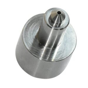


Complex Geometry CNC Machining, Planned From the Drawing
SUUXIANG aligns manufacturability, process routing, critical dimensions and inspection expectations before production commitments are made.
Drawing-Led DFM Review
Review datums, tolerance stack, tool access, wall conditions and machining risks before quotation so requirements are understood early.
Coordinated Process Routes
Plan CNC milling, turning, EDM, grinding and fitting as connected operations for features that cannot be resolved by one process alone.
Critical Dimension Planning
Identify critical-to-quality dimensions, machining allowances and sequence-dependent risks to support practical control of complex geometry CNC machining parts.
Inspection Alignment
Match inspection methods and reporting needs to the drawing, critical features and agreed verification plan before work begins.
Visible Revision Control
Keep drawing revisions, technical decisions and delivery information visible throughout coordinated production and final inspection preparation.
Custom Part and Tooling Families
Drawing-driven components and process routes for mold, connector, die, and custom-machining requirements, reviewed against critical dimensions, materials, inspection needs, and delivery priorities.

CNC Machining Services
Precision CNC machining services for drawing-based custom parts requiring planned milling, turning, multi-axis work, EDM, grinding, fitting, and inspection. RFQ review should define material, critical dimensions, datums, surface requirements, quantity, and documentation before the process route is confirmed.
Upload a Drawing
CNC Milling
Custom CNC milling services for prismatic, contoured, and feature-rich components. Drawing review considers tool access, workholding, datum sequence, internal corners, thread requirements, machining allowance, and the dimensions that require inspection during and after manufacture.
Upload a Drawing
CNC Turning
Precision CNC turning services for shafts, sleeves, bushings, pins, collars, and other rotational components. A practical review addresses concentricity, runout, threads, shoulders, grooves, material condition, tolerances, and any secondary milling, grinding, or EDM operations.
Upload a Drawing
5-Axis Machining
5-axis CNC machining for parts with compound angles, deep features, multiple faces, or difficult-to-reach geometry. Process planning evaluates fixture strategy, cutter reach, collision risk, datum control, surface transitions, and whether simultaneous machining adds value for the drawing requirement.
Upload a Drawing
Swiss & Micro Machining
Swiss machining and micro machining for small, slender, and detail-intensive components where support, concentricity, and feature access matter. Submit dimensions, material, quantity, critical features, surface requirements, and inspection expectations for a suitable production assessment.
Upload a Drawing
Wire & Sinker EDM
Wire EDM and sinker EDM services for hardened features, narrow slots, sharp internal geometry, fine details, and forms beyond practical cutter access. Planning considers wire path or electrode strategy, start holes, flushing, recast-layer expectations, finishing allowance, and inspection criteria.
Upload a Drawing
Precision Grinding
Precision surface and profile grinding for controlled flatness, parallelism, profile, diameter, and finish requirements. Grinding plans should account for stock allowance, heat-treatment sequence, datum surfaces, clamping effects, and the inspection method used to verify critical features.
Upload a Drawing
Mold Core & Cavity Inserts
Precision mold core and cavity inserts produced from customer drawings for injection-mold tooling applications. Review focuses on steel specification, heat treatment, parting and shutoff geometry, cooling or vent features, EDM strategy, grinding stock, mating relationships, and critical mold dimensions.
Upload a Drawing
Ejector & Ejection Components
Ejector pins, sleeves, and ejection components configured to the drawing, mold layout, and operating environment. Define diameters, fits, travel interfaces, hardness or coating requirements, surface finish, lubrication considerations, and the dimensions affecting reliable movement and wear.
Upload a Drawing
Core Pins, Guide & Locating Components
Core pins, guide pins, bushings, and locating components for controlled alignment and repeatable mold operation. Drawing review addresses fit class, concentricity, engagement length, wear surfaces, heat treatment, mating parts, and the datum relationship required across the assembly.
Upload a Drawing
Slides, Lifters, Gates & Mold Accessories
Mold slides, lifters, gates, and accessories manufactured as configurable tooling components rather than assumed stock items. Provide assembly context, travel and clearance requirements, shutoff geometry, material condition, heat treatment, critical interfaces, and inspection priorities.
Upload a Drawing
Connector Mold Components
Precision connector mold components for tooling that forms high-density, fine-pitch, or tightly aligned connector features. Evaluation considers pin geometry, cavity details, insert relationships, EDM access, grinding needs, wear areas, material requirements, and mating-component tolerances.
Upload a Drawing
Stamping Die Components
Precision stamping die components for forming, blanking, piercing, and progressive-die applications. Supply the part drawing with strip or assembly context where relevant, plus material, hardness, profile requirements, clearance-sensitive features, surface finish, and inspection documentation needs.
Upload a Drawing
Injection, MIM, CIM & Overmolding Tooling
Tooling and component work supporting injection molding, metal injection molding, ceramic injection molding, and overmolding within verified production scope. Feasibility depends on drawing details, material and thermal requirements, feature geometry, mold interfaces, quantity, and quality expectations.
Upload a Drawing
Machining Materials
CNC machining materials selected against the drawing’s functional, machining, wear, corrosion, thermal, and heat-treatment requirements. Identify the specified grade, material condition, traceability needs, substitutions policy, and any mating or application conditions before quotation.
Upload a Drawing
Surface Finishes & Heat Treatment
Surface finishing and heat treatment planned around function rather than assumed as standard. State coating, plating, polishing, texture, hardness, distortion risk, masking, cosmetic requirements, and which dimensions must be protected or verified after secondary processing.
Upload a Drawing
Quality, Metrology & Documentation
Precision inspection, metrology, and quality documentation aligned with the order and verified inspection plan. Define critical dimensions, datums, measurement method, sampling or reporting expectations, material records, revision status, and any customer-specific traceability requirements at RFQ stage.
Upload a Drawing
Prototyping & Low-Volume Production
Rapid prototyping and low-volume manufacturing for drawing-driven parts that need process feedback before broader production. Share revision level, quantities by phase, target date, material, critical dimensions, application context, and required inspection evidence to plan a realistic route.
Upload a DrawingMaterials for Complex Geometry CNC Machining

Tool Steels
Used for mold cores, cavity inserts, punches, and wear components where hardness and dimensional stability matter. Grade, pre-hardening condition, heat-treatment route, EDM allowance, and final grinding requirements should be defined in the RFQ.

Stainless Steels
Suitable for corrosion-sensitive tooling, precision assemblies, and machined components requiring a durable finish. Alloy selection affects machinability, workholding, thermal treatment, surface specification, and the inspection approach for critical features.

Aluminum Alloys
Common for prototypes, fixtures, housings, and lightweight machined parts where efficient material removal is valuable. The selected alloy, wall geometry, datum plan, finish requirement, and mating conditions should guide the machining strategy.

Copper Alloys
Applied to EDM electrodes, conductive features, and selected tooling details where thermal or electrical behavior is relevant. Material grade, electrode wear expectations, feature definition, surface condition, and dimensional verification need project-specific review.

Engineering Plastics
Used for prototype parts, insulating components, guides, and application-specific fixtures. Polymer grade, moisture sensitivity, wall thickness, clamping method, temperature exposure, and measurement method should be confirmed before machining begins.
Complex Geometry CNC Machining Process Routes

CNC Milling and Turning
CNC milling and turning establish primary forms, bores, profiles, and rotational features from the drawing. Process planning considers datum access, workholding, tool reach, and machining allowance before subsequent operations.


Wire EDM
Wire EDM cuts precise profiles, narrow slots, internal forms, and hardened material features where conventional cutter access is limited. Wire path, start-hole location, corner requirements, and finishing passes are defined from the drawing.

Sinker EDM
Sinker EDM forms deep cavities, sharp internal details, and geometry requiring an electrode strategy. Electrode design, burn sequence, stock condition, surface expectations, and later fitting requirements guide the planned process.

Precision Grinding
Precision grinding controls functional surfaces, flatness, parallelism, and final stock removal after machining or heat treatment. Grinding allowance, datum sequence, material condition, and measurement method must be aligned before release.

Fitting Inspection
Fitting and inspection verify mating relationships, critical dimensions, and documented requirements against the agreed plan. Results are tied to the current drawing revision, defined datums, inspection method, and order-specific reporting needs.
Complex Geometry CNC Machining: Tooling Components and Applied Features

Core Pin Sets
Custom core pins support detailed mold features, small bores and repeatable locating conditions. SUUXIANG reviews material, hardness sequence, working geometry and critical dimensions against the drawing before confirming the process route.

Guide Locating Parts
Guide pins, bushings and locating elements help establish controlled alignment between mold or die components. Applicability depends on datum relationships, fit requirements, wear expectations and the mating-component information supplied for review.

Ejection Components
Ejector pins, sleeves and related ejection components can be specified for molded-part release and tool movement. Drawing review should clarify clearances, bearing lengths, surface requirements, heat treatment and inspection priorities.

EDM Detail Inserts
Precision inserts can combine CNC machining, wire EDM or sinker EDM for narrow slots, sharp internal details and restricted tool access. Electrode strategy, wire path, finishing allowance and critical surfaces are reviewed before production.

Connector Tooling Details
Connector mold components may incorporate fine cavities, terminal-related features, guide geometry and complex mating interfaces. SUUXIANG evaluates feature access, datum control, material requirements and inspection method from the supplied drawing package.

Die Wear Parts
Stamping-die components such as punches, inserts and locating details can be planned around wear surfaces and assembly relationships. The proposed route depends on material, heat-treatment sequence, grinding stock and dimensional priorities.
About SUUXIANG Precision Manufacturing
SUUXIANG is the sole public-facing brand of Dongguan SuuXiang Precision Mold Co., Ltd., established in 2010 and based on the 2nd Floor of Sanhe Industrial Park in Chang’an Town, Dongguan, Guangdong, China. Founded by legal representative XiaoCheng Huang, the company helps international engineering, sourcing, and quality teams turn controlled drawings and specifications into inspected custom parts, precision mold components, connector tooling, and stamping-die components.
Our work brings CNC milling and turning, multi-axis machining, EDM, precision grinding, fitting, and inspection into a drawing-driven manufacturing workflow. For complex geometry CNC machining, the discussion begins with datums, critical dimensions, machining access, material condition, and the process sequence needed to protect the part’s functional requirements.
What differentiates SUUXIANG is disciplined project communication before production commitments. We review DFM, tolerance stack, electrode or wire-path needs, grinding allowance, heat-treatment sequence, and inspection expectations so the quotation and manufacturing plan reflect the revision-controlled requirement—not an assumption.

How Complex-Geometry CNC Machining Is Planned
DFM Before Toolpaths
Each complex geometry cnc machining review begins with the drawing, model, datums, critical dimensions, material and application context. SUUXIANG identifies machining access, feature interactions and tolerance risks before a process route or production commitment is discussed.
- Confirm critical-to-quality dimensions and datum relationships
- Review wall thickness, internal features and tool reach
- Flag tolerance stacks that need functional clarification
- Align revision status before quotation preparation

Multi-Process Route Planning
Complex parts may require more than a single milling setup. SUUXIANG plans the appropriate sequence across CNC milling or turning, multi-axis work, EDM, grinding and fitting according to the verified geometry, material condition and inspection requirements.
- Separate accessible milled features from EDM-dependent details
- Consider setup direction and workholding stability
- Plan heat-treatment sequence and machining allowance
- Keep process choices tied to drawing requirements

EDM and Grinding Strategy
Deep ribs, sharp internal corners, hardened features and precision mating surfaces require deliberate EDM and grinding decisions. SUUXIANG reviews electrode access, wire paths, finishing stock and surface requirements so these operations support the functional geometry rather than become late-stage corrections.
- Assess wire-EDM entry and exit constraints
- Define electrode strategy for inaccessible cavities
- Reserve grinding stock for controlled finishing
- Review surface and mating requirements together

Inspection Prepared for Production
Inspection planning is part of complex geometry cnc machining, not an afterthought. Before production, SUUXIANG aligns measurable features, datum references, inspection methods and required reporting with the order, helping buyers define the evidence needed for acceptance and traceable delivery.
- Link inspection points to critical drawing callouts
- Clarify datum-based measurement expectations
- Identify requested reports before production begins
- Maintain visible revision and delivery information

Complex Geometry CNC Machining: Beyond a Quotation-Only Supplier
Compare the drawing-review and production controls that matter before complex features enter manufacture.
← Swipe left or right to view →
Complex Geometry CNC Machining: From Drawing Review to Inspection
A controlled workflow aligns manufacturing decisions, critical dimensions, inspection expectations, and delivery information before production commitments are made.
Review Drawings and Requirements
We review 2D drawings, 3D models, material, quantity, application context, critical dimensions, surface requirements, reporting needs, and target delivery date before quotation.
Plan Process and Material
DFM discussion confirms datums, tolerance stack risks, machining access, workholding, heat-treatment sequence, machining allowance, and the appropriate CNC, EDM, or grinding route.
Machine Critical Features
CNC milling, turning, multi-axis machining, Swiss machining, and micro machining are coordinated around feature access, tool strategy, revision control, and specified priorities.
Apply EDM and Grinding
Where geometry or finish requires it, wire EDM, sinker EDM, precision grinding, and fitting are planned with electrode strategy, wire path, stock allowance, and datum control.
Inspect Pack and Coordinate
Completed parts are inspected against the agreed plan, documented as required by the order, protected for shipment, and coordinated with visible revision and delivery information.
Start Complex Geometry CNC Machining With a Complete RFQ
Give SUUXIANG the technical context needed to assess manufacturability, plan inspection, and prepare a responsible quotation.
Submit Your Drawing Package
Upload the 2D drawing and available 3D model, identifying revision level, application context, mating features, and any geometry that requires special tool access.
Define Material and Quantity
Specify material grade, heat-treatment condition or requirement, requested quantity, sampling needs, and target delivery date so the proposed route reflects your actual project.
Identify Critical Requirements
Mark critical dimensions, datums, surface requirements, functional fits, and tolerance priorities. Include inspection-report, traceability, and documentation expectations before quotation review begins.
Review DFM and Process
Discuss machining access, workholding, multi-axis strategy, EDM or grinding needs, allowances, and inspection methods with SUUXIANG before production commitments are confirmed.
Confirm Quote and Sampling
Align on the approved revision, process scope, quality plan, delivery coordination, and any sample requirements before releasing complex geometry CNC machining work to production.
Quality Documentation and Certification Evidence
Customer Evidence Is Published Only When Verified
No customer testimonial is published until customer permission, measurable results, and final project facts have been verified.
Approved case example reserved for verified details on drawing revision, inspection requirements, process route, and measurable production outcome.
Customer feedback reserved until the quoted outcome, customer identity, and permission to publish have been confirmed by the relevant parties.
Complex Geometry CNC Machining FAQ
Practical answers for drawing-driven parts, tooling components and inspection-led sourcing decisions.
What information is needed for a complex geometry CNC machining quote?
Can complex geometry CNC machining handle deep cavities, thin walls and undercuts?
When does complex geometry CNC machining require EDM or grinding?
Will SUUXIANG perform DFM review before production?
How are lead time and sample quantities assessed for complex parts?
What inspection reports can be requested with a CNC machining order?
How does SUUXIANG manage drawing revisions and confidential project files?
Can SUUXIANG arrange shipping for complex geometry CNC machining parts?
Complete Buyer’s Guide to Complex-Geometry CNC Machining
A practical decision framework for evaluating complex parts, choosing capable suppliers, controlling risk and cost, and avoiding drawing, quality, and sourcing mistakes before production.
1. What Is complex geometry cnc machining?
Five-axis motion is often relevant when a drawing combines compound contours, undercuts, deep cavities, thin walls, precision holes, or surfaces that cannot be reached by a standard vertical tool approach. Complex geometry CNC machining describes the access and shape problem created by those interacting features, not simply a part with many dimensions.
A ±0.01 mm tolerance alone does not make a component geometrically complex; it may be achievable on a simple prismatic feature with stable datum access. Complexity rises when tool orientation, cutter reach, collision clearance, feature rigidity, and the number of setups affect whether that tolerance can be produced and verified.
SUUXIANG reviews machine kinematics, CAM toolpaths, workholding, cutting-tool selection, and inspection planning as one drawing-review problem. The review should identify critical datums, inaccessible features, likely deflection points, probe or gauge access, and any need to combine CNC machining with EDM, grinding, fitting, or staged inspection before production is released.
2. How Complex-Part Machining Evolved
Complex-part machining has developed from separate 3-axis milling and 2-axis turning setups toward multi-axis machining, simulation, probing, EDM, grinding, and coordinated inspection. Each additional orientation or inaccessible feature can introduce datum-transfer, workholding, tool-clearance, and verification risks.
5-axis machining can improve access to compound-angle surfaces, deep features, and undercuts, but it does not remove the need to define datums, clamping surfaces, tool reach, and inspection access. CAD/CAM simulation and probing support pre-production review of tool clearance, collision exposure, stock condition, and reference locations.
For an RFQ, provide the current 3D model, controlling drawing revision, and critical-feature datums so the proposed route can be evaluated against the actual design requirement.
3. Types of complex geometry cnc machining
Six process routes cover most complex geometry cnc machining decisions. Request the feature, datum and inspection outcome first; SUUXIANG can then review tool access, setups and the appropriate combined route.
| Route | Reachable Features | Setup Implication | Request When |
|---|---|---|---|
| 3-axis indexed | Open faces, pockets | Multiple orientations | Features are prismatic |
| 3+2 | Angled faces | Fixed tilted setup | Angles need access |
| Simultaneous 5-axis | Compound contours | Fewer re-clamps | Tool orientation matters |
| Mill-turn | Rotary plus milled features | One sequence possible | Concentricity is critical |
| EDM-supported | Sharp, deep internal details | Secondary process | Milling cannot reach |
| Multi-operation | Mixed critical features | Planned datum transfer | Several processes are needed |
Milling Access Routes
3-axis indexed machining suits open pockets, drilled faces and prismatic features; each re-clamp can add datum-transfer risk.
3+2 positioning reaches angled faces with a fixed tool orientation, while simultaneous 5-axis milling follows compound surfaces and can shorten tools for better rigidity.
Rotary And EDM Features
Mill-turn work suits parts combining turned diameters, flats, cross-holes or milled details in one controlled sequence.
EDM-supported work addresses sharp internal corners, narrow ribs, deep slots and hardened features when cutter access or radius limits control the design.
Multi-Operation Planning
Multi-operation machining combines milling, turning, EDM, grinding and fitting when one process cannot protect every critical feature. Submit datum relationships, hardness sequence and inspection priorities instead of prescribing a machine model.
4. Materials for complex geometry cnc machining
Seven material groups drive different decisions in complex geometry cnc machining. Material behavior changes tool access, cycle time, finishing sequence, and the inspection plan.
| Material Group | Machining Consideration | Typical Decision |
|---|---|---|
| Aluminum alloys | Low cutting force; burr control | Lightweight prototypes |
| Stainless steels | Work hardening; corrosion need | Corrosion-resistant assemblies |
| Tool steels | Heat treatment and grinding stock | Mold or die components |
| Brass or copper alloys | Burrs and soft-feature support | Connector components |
| Titanium | Heat and tool wear | High-strength applications |
| Engineering plastics | Low stiffness and clamping risk | Functional prototypes |
Material Comparison
Aluminum favors fast material removal; titanium and tool steel retain heat and can increase tool wear. Copper alloys may form persistent burrs, while engineering plastics need support to limit deflection.
Choose By Application
Mold cores and die components require hardness, wear, and heat-treatment sequencing to be reviewed with grinding stock. Connector parts may prioritize conductivity, corrosion resistance, burr control, and mating-datum stability.
Prototype parts require the intended application, load, temperature, and finish to be stated before alloy substitution is considered.
Confirm Supplied Material
Customer-supplied stock requires grade, condition, size, traceability, and usable-machining allowance confirmation. Material certificates, heat-treatment records, and finish requirements should be tied to the drawing revision and inspection method.
5. Feature Design and Surface-Finish Options
Two drawing controls determine whether a feature is manufacturable: its tolerance relative to a stated datum scheme, and the access available for the cutting or EDM tool. Specify only critical dimensions tightly; uncontrolled tightness increases inspection and process risk.
| Requirement | Drawing Detail | Dimensional Consideration |
|---|---|---|
| Anodizing | Masking and cosmetic zones | State post-anodize dimensions |
| Plating | Thickness and coverage | Allow for deposit buildup |
| Heat treatment | Hardness and sequence | Reserve grinding stock |
| Bead blasting | Applicable faces | Confirm roughness afterward |
| Passivation or marking | Method and location | Protect critical surfaces |
Datums, Threads, And Access
Three datum references can establish a functional setup for location, orientation, and inspection. Put thread callouts, engagement depth, class, and gauging requirement directly on the drawing.
One deep hole requires a defined diameter, depth, bottom condition, and allowable runout from its datum. Internal radii, corner relief, and tool access should be modeled rather than assumed.
Edges And Surface Texture
Two edge requirements are different: a controlled radius protects a functional transition, while an edge break removes a sharp burr. State which edges are excluded when a sealing, press-fit, or cosmetic boundary is involved.
One roughness callout needs its measurement direction and applicable surface clearly identified. Avoid applying a fine finish to surfaces that will be ground, EDM-finished, or coated later.
Finish And Inspection Notes
Two finish interactions need drawing control: anodizing or plating can change final dimensions, and heat treatment can affect distortion or grinding stock. Define whether dimensions apply before or after treatment.
One finish note should identify masking, cosmetic zones, color or passivation requirement, marking location, and post-treatment inspection method. SUUXIANG can review these requirements against the proposed manufacturing route.
6. Quality Elements That Protect Complex Parts
A drawing review for complex geometry cnc machining must convert critical features into an inspection plan before material is cut. Generic tolerance claims are insufficient: each feature depends on access, datum control, material condition, and process route.
DFM And Datum Plan
2D drawings and 3D models should identify functional datums, CTQ dimensions, surface requirements, and mating relationships. The review should flag minimum walls, deep pockets, corner radii, and tool or EDM access before programming.
Stable Cutting And Fixturing
Fixture contact must resist cutting load without distorting thin or unsupported areas. Tool reach, diameter, and stick-out affect deflection, while planned deburring prevents loose burrs from changing edges, fits, or measurement results.
Inspection And Records
In-process probing can verify setup references and selected features before subsequent operations. First-article approval should define whether CMM results, functional gauges, or both prove conformance; revision, material, inspection, and delivery records should remain traceable to the order.
7. Choosing a complex geometry cnc machining Supplier
A purchase order should follow evidence, not a generic equipment list. For complex geometry cnc machining, compare the proposed route against the actual part family, critical datums, and approval requirements.
| Evaluation Area | Question Before PO | Evidence To Request |
|---|---|---|
| Machine And CAM Fit | Can the route reach every feature? | Setup plan and simulation review |
| Inspection | Can critical datums be measured? | Inspection plan and report format |
| Lead Time | What can alter the committed date? | Capacity and risk communication plan |
Match Part Family Experience
The supplier should show comparable cores, inserts, connector tooling, or die components. Ask which features, materials, and operations made those jobs comparable.
- Request redacted first-article examples
- Confirm multi-axis, EDM, and grinding roles
- Identify prior thin-wall or deep-cavity controls
Test The Engineering Response
A drawing review should identify tool access, workholding, datum transfer, machining allowance, and inspection risk. Ask for DFM feedback before release, including unresolved assumptions.
- Who owns CAM and revision review?
- How are fixture risks documented?
- When is customer approval required?
Verify Production Controls
The control plan should connect material records, heat-treatment sequence, in-process checks, and final inspection to the revision. Ask how samples, first articles, capacity changes, and lead-date risks are communicated.
- Define required inspection report
- Agree sample acceptance criteria
- Require written change control
8. Common Complex-Part Sourcing Mistakes
A single incomplete callout can turn a sound complex-part design into added setups, rework, or a disputed inspection result. Review the drawing package before price comparison, when changes are still inexpensive.
Define The Drawing Package
1. Ambiguous notes, missing revisions, and omitted datums leave the supplier to infer function.
2. Provide controlled 2D and 3D files, datum scheme, CTQ dimensions, and mating context; otherwise fit and approval risk increase.
Apply Tolerances And Access
3. Blanket tight tolerances raise grinding, inspection, and cycle-time cost without improving function.
4. Tolerance only critical features, specify surface roughness, and add corner radii or EDM access; inaccessible internal corners can extend lead time and compromise quality.
Validate The Process Route
5. A five-axis machine improves access but does not eliminate tool reach, electrode, wire-EDM, heat-treatment, or finishing constraints.
6. Freeze finish requirements early, compare technical evidence rather than unit price alone, and approve a prototype or first article before production; skipping either can conceal fit or cosmetic failures.
9. From RFQ to Approved Production
A complete RFQ for complex geometry cnc machining begins with controlled design data, not a tolerance-only email. SUUXIANG can review the drawing package against the stated application, quantity, and inspection expectations before a process route is aligned.
Submit a Controlled Package
Two files should travel together: the released 2D drawing and native or neutral 3D CAD. Identify material, heat treatment, finish, annual volume, target date, and mating-part context.
One feature list should flag CTQ dimensions, datums, surface requirements, and functional threads. State which document governs if model and drawing conflict.
- Released drawing revision
- 3D model and format
- CTQ and datum list
- Annual-volume forecast
Close DFM And Quote Assumptions
Three decisions reduce avoidable iterations: machining access, datum-based inspection, and the sequence of heat treatment, EDM, and grinding. SUUXIANG should return DFM questions where tool access, electrode strategy, wire path, or grinding stock affects the result.
One quotation review should document included material, process route, inspection scope, revision, quantity breaks, and delivery assumptions. Resolve exceptions in writing before release.
Approve Production Evidence
One approved sample or first-article record should be tied to the released revision before repeat production. Agree measurement methods, sampling plan, report format, packing protection, and acceptance criteria.
Zero undocumented revisions should enter production. Program managers should issue a dated change notice, confirm disposition of work in process, and retain the accepted inspection record with the purchase order.
10. complex geometry cnc machining Pricing Factors
7 cost drivers—quantity, setup, fixturing, material, machining time, inspection, and finishing—are evaluated after drawing review; complex geometry cnc machining cannot be priced responsibly from a photograph or generic tolerance statement. SUUXIANG should confirm datums, heat treatment, critical features, and required evidence before quoting.
2 quotations with identical unit prices may not include identical work. Compare revision level, programmed setups, fixture or electrode scope, inspection-report content, finish subcontracting, packaging, and expedited-delivery assumptions; request identified exclusions and quote validity.
| Driver | Cost effect | Lead-time effect |
|---|---|---|
| Quantity tier | Low quantities allocate setup across fewer parts | First-article work dominates |
| Setup and fixturing | Extra orientations, fixtures, or electrodes add programming and labor | Design and prove-out extend |
| Material and machining time | Hard alloys, thin walls, and deep cavities increase cutting time and tool wear | Machine occupancy increases |
| Inspection, finishing, urgency | Reports, special finishes, or expedites add coordination; urgency may add premium | Outside processing or queue changes schedule |
Start Your Complex Geometry CNC Machining Review
Upload your drawing with material, quantity, critical dimensions, inspection priorities, and target delivery requirements for a technical quotation review.