
Wire EDM Machining for Precision Parts
Move from drawing review to inspected conductive parts with wire EDM machining, DFM guidance, controlled process planning, and traceable quality documentation.
Representative Wire EDM Components





Related Wire EDM Components and RFQs


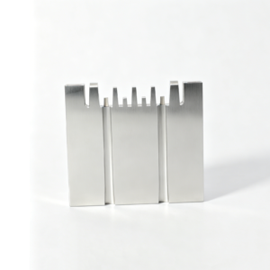


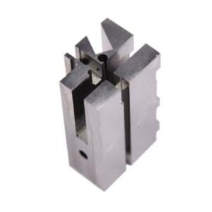


Wire EDM Machining Advantages for Complex Conductive Parts
A drawing-led workflow that aligns DFM, wire path, critical dimensions, inspection expectations, and controlled revisions before production decisions are made.
Drawing-Led DFM Review
Review geometry, datums, material, heat-treatment sequence, and access constraints early to identify manufacturability questions before quotation or production commitments.
Non-Contact Cutting Strategy
Plan wire EDM for conductive profiles where conventional tool access, cutting forces, or intricate contours require a different manufacturing route.
Critical Dimension Planning
Identify critical-to-quality features, tolerance relationships, corner requirements, and finishing needs so machining and EDM decisions follow the drawing intent.
Inspection Aligned Early
Define inspection methods, reporting requirements, datums, and acceptance priorities with the order, helping final documentation match the verified inspection plan.
Controlled Revision Visibility
Keep drawing revisions, project discussions, and delivery information visible throughout manufacturing to reduce ambiguity between engineering, sourcing, and quality teams.
Precision Parts and Tooling We Support
Drawing-driven process routes for configurable precision parts, mold components, connector tooling, die components, and controlled prototype or low-volume requirements.

CNC Machining Services
Precision CNC machining services for drawing-based parts requiring planned milling, turning, EDM, grinding, fitting, and inspection. Review focuses on critical dimensions, datums, material condition, tolerances, surface requirements, and the process sequence needed before production is committed.
Upload a Drawing
CNC Milling
Custom CNC milling services for prismatic, contoured, and feature-rich components. Tool access, fixture strategy, datum setup, stock allowance, corner geometry, and inspection access are reviewed against the drawing and 3D model before machining begins.
Upload a Drawing
CNC Turning
Precision CNC turning services for shafts, sleeves, bushings, pins, and other rotational parts. Quotation review considers concentricity, runout, datum definition, thread requirements, internal features, material condition, and secondary operations such as grinding or EDM.
Upload a Drawing
5-Axis Machining
5-axis CNC machining for components where angled features, compound surfaces, or multiple face relationships benefit from fewer setups. Feasibility depends on tool reach, clamping, datum control, material, feature geometry, and the specified inspection approach.
Upload a Drawing
Swiss & Micro Machining
Swiss machining and micro machining for small, slender, or detail-dense components where support, handling, and measurement require careful planning. Drawing review addresses diameter-to-length relationships, feature access, material behavior, critical tolerances, and inspection method.
Upload a Drawing
Wire & Sinker EDM
Wire EDM and sinker EDM services for profiles, narrow slots, sharp internal forms, hardened materials, and features unsuitable for conventional cutting. Process planning considers wire path, start holes, electrode strategy, flushing, recast-layer considerations, finish requirements, and downstream fitting.
Upload a Drawing
Precision Grinding
Precision surface and profile grinding for flatness, parallelism, profile accuracy, and controlled finishing of precision components. Grinding stock, heat-treatment sequence, datum references, wheel access, surface specification, and inspection criteria should be defined before release.
Upload a Drawing
Mold Core & Cavity Inserts
Precision mold core and cavity inserts produced from customer drawings and models. Manufacturing routes may combine CNC machining, EDM, grinding, heat treatment coordination, fitting, and inspection according to cavity geometry, shutoff conditions, surface requirements, and molding application.
Upload a Drawing
Ejector & Ejection Components
Ejector pins, sleeves, and ejection components for mold assemblies, configured to drawing requirements. Review addresses working diameter, fit class, stroke-related features, head geometry, hardness or treatment requirements, lubrication considerations, and mating-component relationships.
Upload a Drawing
Core Pins, Guide & Locating Components
Core pins, guide pins, and locating components made to support alignment, molding features, and repeatable assembly. Production planning considers datum relationships, fit requirements, straightness, concentricity, material and heat treatment, grinding needs, and inspection of critical interfaces.
Upload a Drawing
Slides, Lifters, Gates & Mold Accessories
Mold slides, lifters, gates, and accessories manufactured as configurable assembly components rather than stock items. Drawing review examines motion interfaces, shutoff geometry, wear areas, cooling or gating details, material condition, machining access, fitting requirements, and mating parts.
Upload a Drawing
Connector Mold Components
Precision connector mold components for insert, terminal, and high-density connector tooling. Engineering review focuses on fine feature geometry, pitch-critical relationships, pin or cavity interfaces, EDM strategy, material and treatment requirements, wear surfaces, and dimensional verification.
Upload a Drawing
Stamping Die Components
Precision stamping die components for forming, piercing, trimming, and related die functions. Process selection considers tool steel condition, cutting-edge geometry, clearance relationships, heat-treatment sequence, wire EDM path, grinding stock, assembly fit, and inspection priorities.
Upload a Drawing
Injection, MIM, CIM & Overmolding Tooling
Injection, MIM, CIM, and overmolding tooling components manufactured within verified project scope. RFQs should identify material flow conditions, molded feature requirements, mating interfaces, surface needs, thermal considerations, critical dimensions, and the expected tooling or component function.
Upload a Drawing
Machining Materials
CNC machining materials selected against drawing requirements, application conditions, machinability, dimensional stability, corrosion needs, and planned treatment. Include the specified grade, condition, material certification needs, and any approved alternatives for a meaningful manufacturability review.
Upload a Drawing
Surface Finishes & Heat Treatment
Surface finishing and heat treatment requirements reviewed as part of the manufacturing sequence, not as isolated add-ons. Specify finish target, roughness or cosmetic expectations, coating or treatment type, hardness requirements, masking needs, dimensional effects, and applicable inspection evidence.
Upload a Drawing
Quality, Metrology & Documentation
Precision inspection, metrology, and quality documentation aligned with the order and verified inspection plan. Define critical dimensions, datums, measurement methods, reporting format, material or treatment records, revision status, sample requirements, and traceability expectations before production.
Upload a Drawing
Prototyping & Low-Volume Production
Rapid prototyping and low-volume manufacturing for teams validating design, fit, function, or supply readiness. A complete RFQ should provide drawings, models, quantity, material, critical features, surface or heat-treatment requirements, inspection needs, revision level, and target delivery date.
Upload a DrawingConductive Materials for Wire EDM Machining

Tool Steel
Common for mold cores, inserts, punches and die components. Pre-hardened or heat-treated condition affects cutting strategy, finishing passes, grinding allowance and inspection planning for critical edges and datums.

Stainless Steel
Selected for corrosion-resistant precision components, tooling details and connector-related applications. Grade, hardness condition and surface requirement are reviewed against the drawing to coordinate wire path, finishing and downstream inspection.

Carbide Grades
Used where wear resistance is central to punches, dies and forming details. Conductive carbide can require a carefully defined EDM route, edge condition and inspection method because geometry, grade and finish priorities affect process planning.

Aluminum Alloys
Applicable to conductive fixtures, prototypes and selected tooling components where low mass or thermal behavior matters. Alloy designation, stock condition and feature geometry are checked to balance wire EDM access, finish expectations and handling.

Copper Alloys
Brass, copper and related conductive alloys may suit electrical, connector and specialty tooling details. Their grade, work-hardening condition and burr sensitivity should be identified so machining, finishing and dimensional verification can be planned.
Wire EDM Machining and Complementary Processes

Wire EDM Cutting
Wire EDM machining uses a programmed wire path to produce intricate through profiles, slots, and tapered features in conductive workpieces. It supports controlled geometry after material condition, datum strategy, cut sequence, and inspection priorities are reviewed.

Sinker EDM Cavities
Sinker EDM uses a formed electrode to create blind cavities, internal details, and shapes not accessible to a wire path. Electrode strategy, spark allowance, surface requirements, and downstream fitting requirements should be defined from the drawing.

CNC Milling and Turning
CNC milling and turning establish stock, datum features, bores, external forms, and machining access before or alongside EDM. The route is planned around material condition, clamping, critical dimensions, remaining stock, and required feature relationships.

Precision Grinding
Precision grinding refines reference surfaces, diameters, and functional fits where controlled stock removal is required. Grinding allowance, heat-treatment sequence, surface requirement, and measurement method are reviewed so finishing work supports the intended assembly relationship.

Fitting Inspection
Fitting and inspection verify that interacting components, critical dimensions, and drawing revisions remain aligned before release. SUUXIANG plans measurement around specified datums, functional interfaces, reporting needs, and order-specific traceability rather than relying on generic checks.
Tooling Features to Define During Wire EDM Review

Locating Features
Dowel holes, datum faces, and locating pockets establish repeatable orientation between mold plates and inserts. Identify functional datums and mating relationships on the drawing so machining and inspection can be planned around the intended assembly condition.

Guide Elements
Guide pins, bushings, and sliding interfaces require clear fit, material, heat-treatment, and lubrication requirements. Their position and alignment affect mold motion, wear behavior, and whether wire EDM, grinding, or finish fitting is needed.

Threaded Features
Tapped holes, threaded inserts, and fastening patterns should specify thread standard, depth, engagement, and any post-treatment sequence. These details help prevent inaccessible features, damaged threads, or tolerance conflicts after heat treatment and finishing.

Wear Inserts
Replaceable inserts can concentrate wear in serviceable components while preserving the surrounding tooling. Provide interface geometry, retention method, material requirements, and critical mating dimensions so SUUXIANG can review the appropriate EDM, grinding, and fitting route.

Part Marking
Part numbers, revision marks, orientation arrows, and cavity identification improve traceability during assembly and inspection. Specify marking location, method, legibility expectations, and whether marks must remain visible after coating, polishing, or use.
About SUUXIANG Precision Manufacturing
SUUXIANG is the sole public-facing brand of Dongguan SuuXiang Precision Mold Co., Ltd., established in 2010 in Chang’an Town, Dongguan, Guangdong, China. Founded by XiaoCheng Huang, the company supports international engineering, sourcing and quality teams with drawing-driven custom CNC parts, precision mold components, connector tooling and stamping-die components.
Our practical manufacturing scope combines CNC milling and turning, multi-axis work, wire EDM machining, sinker EDM, precision grinding, fitting and inspection. Each project begins with the drawing, model, material, quantity, application and quality requirements so the process route can be reviewed before quotation and production commitments.
What differentiates SUUXIANG is disciplined coordination around DFM, critical dimensions, datum strategy, machining access, EDM wire path, grinding allowance, inspection method and revision control. We focus on exchanging the evidence needed to make informed manufacturing decisions and delivering documentation aligned with the agreed inspection plan.

Wire EDM Machining Capability, From DFM to Inspection
Drawing Review Before Release
SUUXIANG reviews the drawing, model, material condition, datums, critical dimensions, surface requirements and quantity before confirming a wire EDM machining route. This identifies access limits, start-hole needs, tolerance-stack risks and inspection priorities while revisions remain controllable.
- Confirm conductive-material and geometry suitability
- Define datums and critical-to-quality dimensions
- Review start-hole, through-cut and wire-access needs
- Align revision, quantity and delivery requirements

Wire Path and Electrode Strategy
Wire EDM machining is planned around the required profile, corner condition, taper, stock condition and finishing expectation. For blind cavities or features beyond a wire path, SUUXIANG evaluates sinker EDM and electrode strategy as part of the process route rather than treating EDM as an isolated operation.
- Plan roughing and finishing passes as required
- Review taper, radii and profile transitions
- Assess wire-cut versus sinker-EDM suitability
- Coordinate electrode needs with final geometry

Grinding and Fitting Coordination
Precision components often require EDM, grinding and fitting to work from the same datum strategy. SUUXIANG coordinates machining allowance, heat-treatment sequence, grinding stock and mating-feature requirements so a finished core, insert, pin or tooling component is evaluated as part of its functional assembly.
- Set allowances before heat treatment and grinding
- Maintain datum continuity between operations
- Review mating faces, clearance and locating features
- Escalate fitting risks during drawing review

Inspection and Revision Traceability
Inspection planning follows the order requirements and identified critical dimensions. SUUXIANG aligns measurement methods, reporting expectations and revision information before production, then keeps manufacturing and delivery communication tied to the approved drawing and verified inspection plan.
- Identify dimensions requiring inspection evidence
- Match reporting needs to the approved order
- Maintain drawing and revision visibility
- Communicate quality and delivery requirements clearly

Why Choose SUUXIANG for Wire EDM Machining
Compare a disciplined drawing-review workflow with quotation-only sourcing for precision parts and tooling.
← Swipe left or right to view →
Controlled Wire EDM Machining Workflow
A drawing-driven route that aligns DFM, process planning, inspection evidence, and delivery coordination before production commitments are made.
Review Drawings and Requirements
We review 2D drawings, models, material, quantity, critical dimensions, datums, surface requirements, inspection needs, application context, revisions, and target delivery requirements.
Plan Process and Controls
The team confirms manufacturability, machining access, wire path, start-hole needs, electrode strategy, grinding stock, heat-treatment sequence, and the inspection plan.
Machine EDM and Grind
Production follows the approved route using CNC machining, wire EDM machining, sinker EDM, precision grinding, and fitting where the drawing and component geometry require.
Verify Critical Part Features
Inspection checks agreed critical dimensions, datum relationships, surface requirements, and other order-specific characteristics against the drawing and verified inspection plan.
Pack Document and Coordinate
Parts are protected for shipment, with order-matched documentation, revision visibility, and delivery coordination maintained so receiving teams can reconcile supplied components.
Start Your Wire EDM Machining Project
Give the engineering team the drawing, requirements, and decision context needed to plan a controlled route from review through inspection.
Upload Your Drawing
Send the 2D drawing and, when available, 3D model with revision status, quantity, application context, and target delivery date for an initial technical review.
Confirm Critical Requirements
Identify conductive material, heat treatment, critical dimensions, datums, surface priorities, inspection reporting, and mating-part constraints before the wire EDM machining route is defined.
Review the DFM Proposal
Evaluate the proposed machining, wire path, EDM, grinding, and inspection approach, including tool access, allowances, revision questions, and quotation assumptions before commitment.
Approve Samples When Needed
For projects requiring validation, review agreed sample dimensions and documentation against the drawing before authorizing the released production plan and quality checkpoints.
Release Controlled Production
Approve the final revision and order details so SUUXIANG can coordinate manufacturing, inspection, traceability, and delivery information against the confirmed project requirements.
Wire EDM Machining Quality Documentation and Certification Evidence

Illustrative Wire EDM Workflow Scenarios
Illustrative scenario: A drawing review identifies datum conflicts before production, allowing the wire EDM route and inspection record to be agreed before release.
Illustrative scenario: Revision visibility from DFM through inspection helps a supplier-quality team reconcile delivered parts with the approved drawing and reporting plan.
Illustrative scenario: Coordinating CNC stock, wire EDM finishing and grinding during review can reduce rework risk for a mold-component order.
Wire EDM Machining FAQ for RFQ Preparation
Practical answers for engineering, sourcing and quality teams preparing drawing-based precision-part inquiries.
What information should I send for a wire edm machining RFQ?
What quantities can SUUXIANG review for wire edm machining?
How should I plan lead time for wire edm machining parts?
Can I order samples before a production release?
What materials are suitable for wire EDM?
Can wire EDM achieve my required tolerance and surface finish?
What inspection documents can I request with my order?
How are shipping, payment and confidential drawings handled?
The Complete Buyer’s Guide to wire edm machining
Use this decision framework to evaluate wire EDM fit, DFM constraints, quality controls, supplier criteria, and cost drivers—while avoiding specification and sourcing mistakes that delay precision tooling and production parts.
1. What Is wire edm machining?
Wire EDM, or wire electrical-discharge machining, guides a continuously fed, electrically charged wire electrode through conductive material using CNC motion. Electrical discharges remove material across a controlled gap without mechanical contact, while dielectric fluid insulates, cools and flushes eroded particles.
Because wire EDM is a through-cut process, the wire must enter from an edge or a predrilled start hole and cut through the section. It is often considered for intricate profiles, narrow features, punches, dies and hardened-metal mold components where cutter force or tool access makes milling less suitable. Open pockets, broad stock removal and many 3D surfaces may require milling or a combined route. Buyers should specify the profile, thickness, start-hole allowance, datum scheme and finish priorities before selecting a process.
2. How wire edm machining Evolved
1770: Joseph Priestley recorded electrode material loss from electrical discharge, an observation now described as electro-discharge erosion. That early phenomenon established the thermal-removal principle behind EDM. Source: https://www.xactedm.com/how-edm-works
1940s: Soviet researchers Boris and Natalya Lazarenko developed a controlled discharge process that became a foundation for modern EDM. Their work shifted spark erosion from an incidental effect toward a usable method for difficult conductive materials. Source: https://www.xactedm.com/how-edm-works
1967: punch-card-controlled wire-eroder experiments marked an early route to programmed wire cutting; later CNC control made complex profiles more repeatable. For modern mold inserts, stamping punches, connector-tooling details, and other drawing-based parts, buyers should specify profile datums, wire-entry locations, taper requirements, and inspection criteria—not assume a complex contour is automatically manufacturable. Source: https://www.rapiddirect.com/blog/what-is-wire-edm
3. Types of wire edm machining
Wire EDM routes differ by cut sequence, profile relationship, and feature scale. Select the route from the drawing’s functional faces, datums, finish requirement, and allowable lead time.
Rough Cutting
First-cut roughing removes most stock quickly; it leaves allowance for later passes. Use it for die blocks and inserts; provide stock thickness, profile, datum faces, and finish-critical edges.
Skim Pass Finishing
One or more skim passes refine size and surface after roughing, trading cycle time for finish. Use them on mating profiles; specify final tolerance, surface requirement, inspection datum, and recast-layer concerns.
Straight-Profile Cutting
A straight profile keeps the same contour through thickness, simplifying programming and inspection. Use it for punches and plates; supply thickness, closed-profile geometry, start-hole location, corner requirements, and burr direction.
Taper Cutting
Taper cutting creates different top and bottom profiles through coordinated wire motion. Use it for clearance angles; provide both profiles, taper angle or coordinates, thickness, datum orientation, and permitted transition zones.
Fine-Wire Micro Features
Fine wire supports narrow slots and small radii but reduces cutting stability and speed. Use it for connector details; provide minimum web, internal radius, feature tolerance, material condition, and breakage-sensitive areas.
4. Materials for wire edm machining
Workpiece conductivity is fundamental to standard wire edm machining because the discharge circuit must close through the part. Material selection also changes cut stability, thermal response, and inspection planning.
| Material Family | EDM Suitability | Common Parts | Buyer Considerations |
|---|---|---|---|
| Tool steel | High | Dies, inserts | Hardness, grind stock |
| Stainless | High | Pins, profiles | Thickness, passivation |
| Carbide | High | Punches | Edge inspection |
| Titanium/nickel | Conditional | Custom profiles | Heat response |
| Aluminum/copper | Conditional | Fixtures, electrodes | Flushing, burrs |
| Nonconductors | Unsuitable | Plastic, ceramic | Alternative process |
Tool And Hardened Steels
Hardened steels suit punches, dies, and mold inserts. State hardness, thickness, datum, and grind stock.
Stainless Steels
Conductive stainless supports corrosion-resistant profiles and pins. Confirm grade, section thickness, passivation, and inspection sequence.
Carbide
Carbide suits wear parts and fine punch features. Specify grade, fragile edges, thickness, and chipping inspection.
Titanium And Nickel Alloys
Titanium and nickel alloys are conductive but heat-sensitive. Define alloy, thickness, surface requirement, and downstream inspection.
Aluminum And Copper Alloys
Aluminum and copper cut electrically but demand stable flushing. Identify alloy, thin features, burr limits, and handling needs.
Conductivity Limitations
Nonconductive plastics and ordinary ceramics cannot use standard wire EDM. Discuss conductive coatings or another process before quoting.
5. Wire, Finish, and Taper Options
Two wire choices, pass strategy, and U/V-axis taper programming affect cut behavior and downstream fitting. Specify them from the function of each feature, rather than treating a quoted finish as universal.
| Specification Choice | Primary Effect | Drawing Callout |
|---|---|---|
| Wire diameter | Corner radius and kerf | Minimum internal radius |
| Skim passes | Finish and size refinement | Critical surface and Ra target |
| Taper profile | Top-to-bottom geometry | Datum, angle, and direction |
Wire Selection And Corners
Brass wire is a common baseline; coated wire can be considered where section thickness, stability, or productivity justifies it. Smaller wire can support tighter internal radii, but kerf, flushing, and wire-path access still govern the achievable contour.
Roughing And Skim Passes
One roughing pass prioritizes material removal, while skim passes refine size and surface condition. Call out critical faces, sealing edges, and mating features, then agree the pass plan and inspection method during drawing review.
Tapers And Secondary Finish
U/V-axis motion can create straight, stepped, or variable taper profiles when the machine setup and geometry permit. Identify taper datum, angular tolerance, edge-break limits, and whether deburring or polishing may change a functional edge.
6. Critical Quality Controls
Quality control begins before programming: the drawing must establish what acceptance means for each critical feature. For wire edm machining, SUUXIANG should review datums, process access, inspection evidence, and revision status against the order.
Datums And CTQs
Each CTQ should name its datum reference, tolerance, measurement method, and reporting requirement. Do not apply a general tolerance to unrelated geometry.
One profile may require position to a functional datum, while another needs only a size limit. Allocate tighter tolerances only where mating, sealing, or tooling function requires them.
Offset And Cut Stability
Each programmed contour needs verified wire diameter, spark-gap offset, and rough-to-skim strategy. The released program must correspond to the current drawing revision.
Thin walls and deep cuts require a stability review because flushing and wire deflection can influence shape. Define start-hole location, closed-contour entry, and any protected features before release.
Corners And Surface Integrity
Every internal corner retains a radius governed by the wire path; specify a functional minimum radius rather than implying a sharp corner. Confirm whether a relief, sinker EDM feature, or design change is needed.
Each finish-sensitive surface needs an agreed process route and acceptance criterion. Where recast-layer concerns affect service, define the required evaluation before production.
Inspection And Records
Each lot should have an inspection plan tied to CTQs, datums, instruments, sampling, and acceptance criteria. Request first-article, in-process, or final records according to project risk.
Material identification, heat-treatment evidence when specified, measured results, and revision-controlled documents should remain traceable to the order. Agree any nonconformance workflow before shipment.
7. Choosing a wire edm machining Supplier
A credible wire edm machining supplier evaluates the drawing before committing a process route. SUUXIANG bases project discussion on critical dimensions, datums, material condition, inspection needs, revision control, and delivery requirements.
Drawing Review And DFM
2D drawings define tolerances, datums, finish, and revision; 3D models clarify geometry. Ask for a documented DFM response identifying start-hole, wire-path, taper, and grinding-stock constraints.
RFQs should state material, heat treatment, quantity, application context, and required delivery date. Missing inputs turn a quotation into an assumption list.
Process And Capacity Fit
Machine envelope and programmed axes must suit the part’s thickness, contour, and taper. Confirm workholding access, wire-threading approach, and whether milling, EDM, grinding, and fitting require coordinated routing.
Material condition affects cutting strategy and dimensional risk. Require agreement on heat-treatment sequence, machining allowance, flushing considerations, and any post-EDM finishing.
Inspection And Tooling Experience
Inspection plans should connect each critical feature to a method, datum setup, and report requirement. Request sample reporting format, measurement responsibility, and traceability for drawing revisions.
Tooling experience matters for cores, inserts, punches, and connector components because mating relationships drive priorities. Evaluate how the supplier communicates deviations, rework decisions, and inspection findings.
Launch And Scale Planning
Prototype quantities need the same revision discipline as low-volume releases. Confirm milestone dates for material, machining, inspection, approval, and shipment before production begins.
SUUXIANG supports drawing-based precision work within verified scope. Compare suppliers on their ability to maintain documented communication when quantities, revisions, or delivery priorities change.
8. Common wire edm machining Buying Mistakes
One RFQ can prevent avoidable rework when it identifies the conductive material, functional features, inspection basis, and loading constraints before programming begins. For wire edm machining, incomplete intent usually reappears as added setup, recuts, or approval delay.
Confirm Material And Process Fit
Electrical conductivity is required; do not specify plastics or other nonconductive stock for wire EDM. Prevent delay by confirming material and considering milling, grinding, or another route where appropriate.
One process rarely replaces milling: wire cutting needs a through path and is not the universal answer for blind pockets or broad stock removal. Request a process review to avoid an unnecessarily slow or costly route.
Define Geometry And References
Two datum references and tolerances should accompany every critical contour, hole relationship, and thickness requirement. Prevent quality disputes by marking the inspection datum scheme on the drawing.
One wire path needs entry access, and inside corners retain a radius related to wire and kerf. Confirm minimum radii, edge-start permission, and profile access before release to prevent redesign or secondary work.
State Finish In Functional Terms
One finish callout without mating, sealing, fatigue, or cosmetic context can drive unnecessary skim passes. State the functional surface, roughness requirement, and acceptable recast or deburring approach to control cost and schedule.
Plan Starts And Workholding
One closed internal profile requires a start hole unless the wire can enter from an edge. Specify permissible hole location, stock condition, and fixture-sensitive faces early to prevent extra drilling, clamping changes, or datum loss.
Compare Evidence Beyond Unit Price
One low unit price may omit programming, start holes, inspection reporting, revision control, or packing assumptions. Compare like-for-like scope, inspection method, delivery commitment, and change handling before selecting a supplier.
9. Launching an EDM Part Project
First, confirm that wire edm machining fits the conductive material, through-cut geometry, taper, and finish requirement. SUUXIANG should review the drawing package before committing a process route for mold, connector, die, prototype, or low-volume parts.
Confirm Process Fit
Before quotation, identify start-hole access, wire path, stock condition, and any grinding or sinker-EDM operations. A stamping punch or connector insert may need a different sequence after heat treatment.
Release Controlled Data
One released 2D drawing should define revision, datums, tolerances, material, heat treatment, and surface requirements. Include the matching 3D model and flag features where model and drawing could be interpreted differently.
Define Inspection Evidence
Critical-to-quality features need a stated inspection method, reporting expectation, and acceptance basis before machining begins. For a mold core, include mating interfaces; for a prototype, identify dimensions that affect the functional test.
Close The Launch Loop
First articles are appropriate when a new revision, mating relationship, or critical profile creates uncertainty. Record approved results, DFM decisions, and revision status so repeat orders reference the same controlled package.
10. wire edm machining Pricing and Cost
1 drawing package—2D drawing plus model when available—gives a supplier the geometry, datum and acceptance context needed to price wire edm machining responsibly. Universal price lists omit stock condition, cut length, pass strategy and inspection scope.
2 parts with identical outside dimensions can quote differently when one requires tapered profiles, fine-wire cutting, extra skim passes or documented measurement. Compare quotations only after aligning revision, quantity, target date and the required inspection record.
| Quote driver | Lower-cost condition | Cost-increasing condition | Information required |
|---|---|---|---|
| Material and stock | Available conductive stock; modest thickness | Large or thick stock; special grade or heat-treatment condition | Material, stock size, thickness, condition |
| Contour and wire | Short, open contour; standard wire | Long or intricate contour; small features; higher wire use | Cut length, start holes, minimum radii |
| Accuracy and taper | Rough-cut acceptance | Tight tolerance, skim passes, taper or variable profile | CTQs, datums, tolerance and taper callouts |
| Setup and inspection | Simple holding; basic verification | Dedicated fixturing; first article or dimensional report | Quantity, inspection plan, reporting format |
| Schedule | Planned release | Expedited sequencing or split delivery | Required delivery date and shipment priorities |
Start Your Wire EDM Machining Drawing Review
Upload your drawing with material, quantity, critical dimensions, delivery target, and inspection needs for a focused manufacturability review before quotation.