
Custom Machined Parts, Reviewed Before Production
SUUXIANG turns drawings into inspected custom machined parts through DFM review, CNC machining, EDM, grinding, and controlled inspection planning.
Featured Custom Machined Parts






Related Custom Machined Parts Catalogue & Quotation




Engineering Advantages for Custom Machined Parts
Turn drawing requirements into a controlled machining and inspection plan before production commitments are made.
DFM Before Quotation
Review geometry, tool access, material requirements, and likely manufacturing risks before pricing or production commitments are finalized.
Critical Dimensions First
Identify critical-to-quality dimensions, datum relationships, and tolerance stacks so machining and inspection priorities remain aligned.
Process Route Planning
Select an appropriate CNC, EDM, grinding, and fitting sequence based on geometry, access, surface requirements, and allowance strategy.
Inspection Plan Alignment
Define inspection methods and reporting expectations against the drawing, critical features, and verified order requirements.
Controlled Revision Handling
Keep drawing revisions, manufacturing changes, and delivery information visible to reduce avoidable interpretation errors.
Traceable Project Communication
Coordinate technical questions, quality expectations, and delivery updates through a documented project workflow for custom machined parts.
Custom Parts, Mold Components and Tooling
Drawing-driven process routes for precision parts and tooling, reviewed against critical dimensions, material requirements, inspection needs and delivery constraints.

CNC Machining Services
Precision CNC machining services for drawing-based custom parts requiring coordinated milling, turning, EDM, grinding and inspection. Quotation review identifies critical dimensions, datum strategy, material requirements and practical machining access before a process route is committed.
Upload a Drawing
CNC Milling
Custom CNC milling services for prismatic, contoured and feature-rich components. Reviews consider tool access, workholding, internal corners, thread and bore requirements, machining allowance, and inspection datums so the part can be produced and measured against the drawing.
Upload a Drawing
CNC Turning
Precision CNC turning services for shafts, sleeves, pins, threaded forms and rotational parts. Material condition, concentricity, runout, shoulder geometry and post-machining grinding or heat-treatment requirements are assessed during drawing review.
Upload a Drawing
5-Axis Machining
5-axis CNC machining supports complex surfaces, angled features and multi-face parts where fewer setups can help protect positional relationships. Feasibility depends on part geometry, tool reach, clamping strategy, material condition and the specified inspection approach.
Upload a Drawing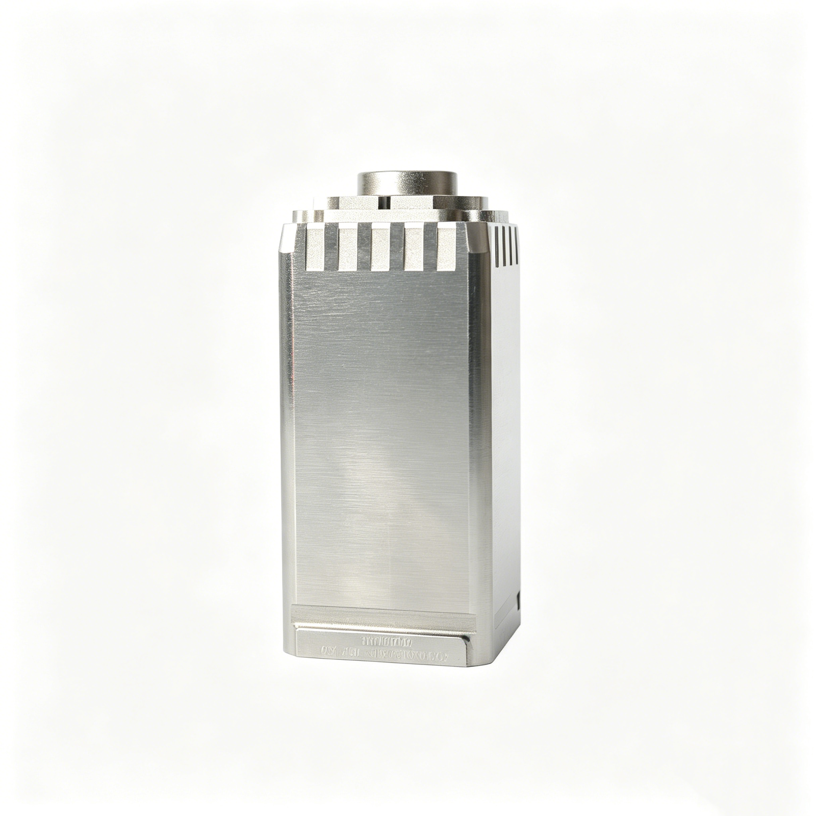
Swiss & Micro Machining
Swiss machining and micro machining support small, slender or feature-dense parts where stability, concentricity and handling matter. Drawings should identify critical diameters, length-to-diameter relationships, burr limits, material condition and measurement requirements.
Upload a Drawing
Wire & Sinker EDM
Wire EDM services and sinker EDM services address hardened materials, narrow slots, sharp internal profiles, intricate cavities and features with limited conventional tool access. Electrode strategy, wire path, flushing, recast-layer considerations and finishing requirements should be defined early.
Upload a Drawing
Precision Grinding
Precision surface and profile grinding supports controlled flatness, parallelism, profile form and final-size adjustment. The process plan evaluates heat-treatment sequence, available grinding stock, datum condition, wheel access and the method used to verify critical dimensions.
Upload a Drawing
Mold Core Inserts & Cavity Inserts
Precision mold core and cavity inserts are produced from drawing and model data with attention to steel selection, heat-treatment sequence, EDM strategy, shutoff geometry, cooling features and final fitting interfaces. Critical dimensions require a defined inspection plan.
Upload a Drawing
Ejector & Ejection Components
Ejector pins, sleeves and ejection components are made for controlled movement and repeatable mold operation. Requirements should clarify fit relationships, hardness or treatment, surface condition, lubrication considerations, mating parts and dimensional inspection priorities.
Upload a Drawing
Core Pins, Guide & Locating Components
Core pins, guide pins and locating components require careful control of diameter, straightness, concentricity, engagement and mating interfaces. SUUXIANG reviews material, heat treatment, grinding and inspection needs against the assembly function before production.
Upload a Drawing
Slides, Lifters, Gates & Mold Accessories
Mold slides, lifters, gates and accessories are configurable tooling components requiring coordinated geometry and fitting. Drawing review considers travel and interference, contact surfaces, wear areas, cooling or venting details, machining access and the relationships to mating mold elements.
Upload a Drawing
Connector Mold Components
Precision connector mold components support high-density connector tooling where pin geometry, cavity alignment, insert interfaces and repeated molding performance matter. Buyers should provide mating-component context, critical feature priorities, material requirements and inspection expectations.
Upload a Drawing
Stamping Die Components
Precision stamping die components are produced for die assemblies where alignment, wear surfaces, cutting relationships and assembly fit affect downstream operation. Manufacturing review addresses material and heat-treatment requirements, grinding stock, EDM features, tolerances and inspection references.
Upload a Drawing
Injection Mold Components, MIM, CIM & Overmolding Tooling
Injection, MIM, CIM and overmolding tooling components are evaluated within verified production scope. Drawings should define resin or feedstock context, molding interfaces, critical shutoffs, venting or gate features, surface requirements and the component’s role in the tooling assembly.
Upload a Drawing
Machining Materials
CNC machining materials are selected against functional requirements, machinability, heat-treatment sequence, corrosion exposure and inspection needs. RFQs should state material grade or approved alternatives, required certificates where applicable, material condition and application context.
Upload a Drawing
Surface Finishes & Heat Treatment
Surface finishing and heat treatment are planned as part of the dimensional process route, not added after machining without review. Specify finish type, roughness or appearance requirements, treatment condition, masking needs, corrosion expectations and dimensions affected by post-process change.
Upload a Drawing
Quality, Metrology & Documentation
Precision inspection, metrology and quality documentation are aligned to the drawing, revision and agreed inspection plan. Buyers should identify critical-to-quality dimensions, reporting format, sampling expectations, material or treatment records and traceability requirements before production.
Upload a Drawing
Prototyping & Low-Volume Production
Rapid prototyping and low-volume manufacturing support drawing-based validation parts, tooling trials and controlled production quantities. Early review focuses on material, critical dimensions, process route, finishing, inspection evidence, revision status and the target delivery date.
Upload a DrawingMaterials for Custom Machined Parts

Tool Steel
Selected for mold cores, cavity inserts, punches, and wear-focused tooling where hardness and dimensional stability matter. Machining, EDM, grinding allowance, and heat-treatment sequence must be evaluated against the specified grade and geometry.

Stainless Steel
Used for corrosion-resistant components, connector tooling, and industrial assemblies exposed to moisture or process media. Grade selection affects machinability, surface finish, and post-machining treatment requirements, which are reviewed from the drawing and application.

Alloy Steel
Suitable for structural machine parts, die components, shafts, and locating features requiring strength and toughness. The proposed process route considers stock condition, heat treatment, machining access, and grinding stock before production planning.

Aluminum Alloys
A practical option for lightweight fixtures, housings, prototype components, and thermal-management parts. Alloy and temper influence chip control, rigidity, thread strength, and surface-treatment compatibility, so requirements should accompany the RFQ.

Copper Alloys
Applied to conductive inserts, electrical-contact tooling, and components needing thermal transfer or corrosion resistance. Brass, bronze, and copper grades machine differently; feature geometry, burr control, and functional requirements require drawing-based verification.
Custom Machined Parts: Machining, EDM & Grinding

CNC Milling
CNC milling removes material from multiple faces to form prismatic features, pockets, contours and datum surfaces. It is evaluated where tool access, setup strategy and surface requirements support stable machining and inspectable geometry.

CNC Turning
CNC turning forms rotational diameters, bores, threads and concentric features from bar or prepared stock. Process planning considers part holding, runout control, wall rigidity and the relationship between turned features and functional datums.

Wire EDM
Wire EDM cuts precise profiles, narrow slots and hardened material features using a programmed wire path. It is considered when conventional cutter access is limited and profile accuracy, corner detail or distortion control requires a non-contact route.

Sinker EDM
Sinker EDM uses a shaped electrode to generate deep cavities, internal forms and difficult-to-reach mold details. Electrode design, spark allowance, surface expectations and subsequent finishing requirements are reviewed with the drawing.

Precision Grinding
Precision grinding refines critical flatness, parallelism, diameter and finish after machining or heat treatment. The route accounts for grinding stock, datum stability, heat-treatment sequence and the inspection method needed for each controlled feature.

Fitting Inspection
Fitting and inspection verify the functional relationship of mating features, movement and critical dimensions before release. The plan follows agreed drawings, revision status and measurement requirements, keeping results aligned with the order documentation.
Custom Machined Parts: Functional Hardware & Mold Accessories

Guide Components
Guide pillars, bushings, and locating features can be machined to support repeatable mold alignment. Define datum relationships, fit requirements, wear conditions, and mating-component details during drawing review.

Core Pins
Core pins are configurable precision elements for forming detailed features and managing localized wear. Provide the pin geometry, material and heat-treatment requirement, support condition, and critical dimensional callouts.

Ejector Parts
Ejector pins, sleeves, and related ejection components are planned around travel, clearance, guidance, and contact surfaces. Drawing review helps identify grinding, EDM, fitting, and inspection needs before manufacture.

Slides Lifters
Slides and lifters address undercuts and controlled mold movement in a configured assembly. Share motion interfaces, locating surfaces, working clearances, material requirements, and assembly context for a practical process route.

Gate Inserts
Gate inserts and related flow-control details require attention to geometry, surface condition, wear exposure, and mating interfaces. Include the molding application and critical features so the appropriate machining or EDM strategy can be reviewed.
About SUUXIANG Precision Manufacturing
SUUXIANG is the sole public-facing brand of Dongguan SuuXiang Precision Mold Co., Ltd., established in 2010 and based at the 2nd Floor of Sanhe Industrial Park in Chang’an Town, Dongguan, Guangdong, China. Founded by XiaoCheng Huang, the company helps international engineering, sourcing, and quality teams convert drawings and specifications into inspected custom machined parts, precision mold components, and connector-tooling components.
Our work brings CNC milling and turning, multi-axis machining, EDM, precision grinding, fitting, and inspection into a coordinated manufacturing route. Before quotation or production commitments, we review DFM, critical dimensions, datums, material and heat-treatment requirements, machining access, and the inspection evidence required for the order.
What distinguishes SUUXIANG is a drawing-driven workflow built around technical clarity. We keep revision control, process decisions, inspection planning, and delivery coordination visible so teams can evaluate manufacturability and quality expectations before parts move into production.

How SUUXIANG Controls Custom Machined Parts
DFM Starts With the Datum
Before quotation or production planning, SUUXIANG reviews the drawing package to clarify functional datums, critical dimensions, tolerance relationships, machining access, material requirements, and surface priorities. This helps identify manufacturability questions while changes are still manageable.
- Review 2D drawings and available 3D models
- Identify critical-to-quality dimensions and datum strategy
- Check tool access, wall conditions, and feature sequence
- Confirm material, heat treatment, quantity, and application context

Process Routes Match Geometry
Custom machined parts may require more than one operation to protect precision and fit. SUUXIANG plans the appropriate combination of CNC milling, turning, multi-axis machining, fitting, EDM, grinding, and inspection according to the drawing, part geometry, and confirmed project requirements.
- Select milling or turning around part geometry
- Plan secondary operations before machining begins
- Coordinate multi-axis work where access supports it
- Keep process decisions tied to drawing requirements

EDM and Grinding Are Planned
For hardened materials, fine internal features, sharp geometry, or controlled finishing surfaces, EDM and grinding need deliberate sequencing. SUUXIANG reviews electrode or wire path needs, grinding stock, heat-treatment sequence, and finishing priorities so these operations support the specified dimensions and mating conditions.
- Assess wire EDM or sinker EDM requirements
- Allow appropriate stock for precision grinding
- Review heat-treatment sequence before final finishing
- Align finishing choices with functional surfaces

Inspection Follows the Revision
Inspection planning is linked to the approved drawing revision and the project’s defined quality expectations. SUUXIANG keeps revision, dimensional, and delivery information visible through coordination, then prepares final documentation to match the order and verified inspection plan.
- Define inspection methods for critical features
- Maintain drawing-revision visibility through production
- Align reports with agreed order requirements
- Coordinate delivery information with project status

Why Engineering Teams Choose a Controlled Workflow
Custom machined parts require visible decisions from drawing review through inspection—not a quote-first handoff.
← Swipe left or right to view →
Custom Machined Parts: From Drawing Review to Delivery
Each project follows a drawing-led workflow that aligns process planning, critical dimensions, inspection requirements and delivery coordination before production commitments are made.
Review RFQ Package
Submit drawings, models, material, quantity, application context, quality requirements and target date so the project team can identify missing production information early.
Plan DFM and Datums
Review critical dimensions, datum strategy, tolerance stack, machining access, heat-treatment sequence and inspection method before confirming a practical process route.
Machine Primary Geometry
CNC milling, turning, multi-axis or micro-machining operations establish the required geometry, leaving controlled stock where subsequent EDM or grinding requires it.
Apply EDM or Grinding
Wire EDM, sinker EDM and precision grinding are selected where geometry, hardened material, surface requirements or final dimensional control call for them.
Fit and Inspect Parts
Components are fitted when required, then checked against the agreed drawing revision and inspection plan, with documentation matched to the verified order requirements.
Pack and Coordinate Delivery
Accepted parts are protected for shipment while revision status, inspection records and delivery coordination remain visible for the receiving team’s planned acceptance process.
How to Work with SUUXIANG on Custom Machined Parts
Move from drawing review to inspected delivery with clear technical inputs, controlled revisions, and agreed quality expectations.
Submit Your Drawing Package
Provide 2D drawings, 3D models when available, material, quantity, application context, target date, and dimensional, surface, heat-treatment, and inspection requirements.
Align DFM and Quotation
Review critical dimensions, datums, tolerance stack, machining access, EDM or grinding needs, and feasible process routes before quotation and production commitments.
Confirm Production Details
Approve the agreed revision, material route, quality plan, and any sample or first-article requirements so custom machined parts proceed against documented expectations.
Coordinate Inspected Delivery
SUUXIANG machines, EDMs, grinds, fits, and inspects according to the confirmed plan, then coordinates delivery with applicable inspection documentation and revision traceability.
Quality Evidence for Custom Machined Parts
Custom Machined Parts: Customer Feedback Pending Verification
This card is reserved for verified customer feedback on custom machined parts, including attributable project scope, inspection evidence, delivery context, and customer-approved outcome data before publication.
This card is reserved for a documented mold-component or connector-tooling project, with customer-approved comments and measurable results linked to the relevant drawing revision and inspection plan.
This card is reserved for evidence-backed feedback from an engineering or sourcing team, including confirmed quantities, critical-dimension requirements, and the verified manufacturing outcome for the project.
Custom Machined Parts FAQ for B2B Buyers
Practical guidance for preparing a drawing-based machining RFQ, defining quality expectations, and planning a controlled project discussion.
What is the minimum order quantity for custom machined parts?
Can I order a prototype or sample before production?
How long do custom machined parts take to manufacture?
What files should I send for a custom machined parts quote?
Can SUUXIANG work with customer-specified materials and heat treatment?
What inspection reports can be provided with an order?
How are shipping, payment, and IP protection handled for machining RFQs?
The Complete Buyer’s Guide to Custom Machined Parts
Use this decision framework to specify, compare, and source drawing-based CNC components with confidence—covering supplier criteria, manufacturability, quality controls, cost drivers, and avoidable purchasing mistakes.
1. What Are Custom Machined Parts?
Custom machined parts are components controlled by a buyer’s 2D drawing, CAD model, and specification. Their geometry, material, tolerances, datums, surface condition, and inspection requirements are selected for a particular application rather than taken from a catalog.
The decision usually begins with two options: adapt a catalog component or specify a custom one. Use a custom component when fit, load path, mating geometry, wear life, sealing, electrical interface, assembly space, or traceable critical dimensions cannot be responsibly resolved through an available standard part.
Several process families may contribute to one finished component: CNC milling forms prismatic features; turning produces rotational geometry; grinding controls selected surfaces; wire or sinker EDM creates inaccessible or hardened details; fitting, heat treatment, finishing, and inspection complete the route. The drawing review should identify the functional datum scheme and critical features before a process plan is assumed.
An RFQ should include the drawing, 3D model where available, material and heat-treatment condition, quantity, finish requirements, critical dimensions, and inspection expectations. That evidence lets SUUXIANG assess manufacturability and propose a controlled route within verified scope.
2. How Precision Machining Evolved
Numerical control began moving machining from hand-guided, dedicated setups toward programmed motion. For buyers, the important shift was that an approved program could be reused, reducing dependence on an individual operator’s interpretation of a drawing.
CNC linked CAD geometry, CAM toolpaths, and controlled machine motion into a more traceable workflow. Revision changes could be translated into updated programs and setup instructions, shortening prototype iterations while making repeat orders more comparable.
Multi-axis positioning, turning-milling combinations, EDM, grinding, and digital metrology extended that advantage to features that are difficult to reach in one orientation. Fewer re-clampings can reduce datum-transfer risk, but sourcing teams should still ask how critical dimensions are held, inspected, and recorded across every operation.
Digital documentation is not implied by CNC alone. A capable supplier should connect the released drawing revision, process route, inspection method, and final report so custom machined parts can progress from first articles to controlled low-volume or repeat production.
3. Types of Custom Machined Parts
Part family determines the likely process route, inspection setup, and questions that must be resolved before quotation. Classify geometry first; then review datums, critical features, and mating conditions.
Turned Parts
Rotational parts include shafts, pins, bushings, and threaded bodies. CNC turning or Swiss machining requires diameters, runout, thread standard, and datum callouts; ask whether features remain concentric after secondary work.
Milled Prismatic Parts
Flat-faced housings, plates, brackets, and blocks use CNC milling. Pocket depth, corner radii, tool access, and flatness drive feasibility; ask which faces locate the assembly.
Mill-Turn Parts

Mixed rotational and cross-machined geometry may combine turning and milling. Define the transfer datum, cross-hole orientation, and backside features; ask whether one setup sequence protects positional relationships.
Precision Mold Components

Mold cores, cavity inserts, slides, and ejector parts often combine CNC, EDM, grinding, and fitting. Specify steel condition, shutoff surfaces, EDM strategy, grinding stock, and inspection datums; ask what changes after heat treatment.
Connector And Tooling Parts
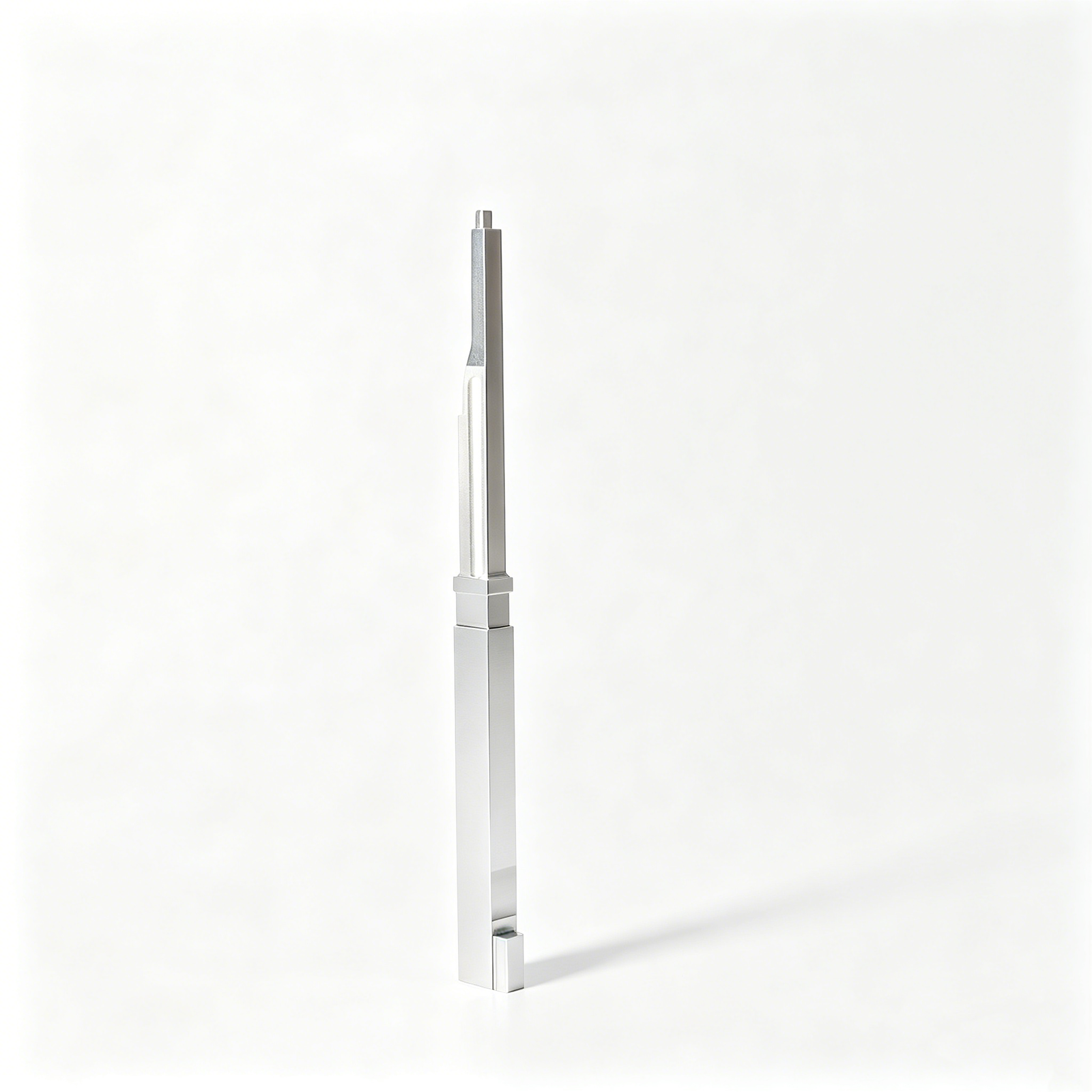
Connector tooling commonly uses fine pins, inserts, guide elements, and stamping-die features. Call out mating geometry, burr direction, edge condition, and wear surfaces; ask which dimensions control connector fit or die alignment.
Prototype And Low-Volume Assemblies
Small builds may contain machined parts plus fitted companion components. Supply the BOM, revision level, assembly sequence, and acceptance criteria; ask which interfaces require first-article evidence before the full lot.
4. Materials for Custom Machined Parts
Material selection for custom machined parts starts with function, service environment, and verification requirements. Compare the complete process route, including heat treatment, finish, and inspection—not unit price alone.
| Family | Primary Decision | Watchpoint |
|---|---|---|
| Aluminum | Low weight, heat transfer | Surface protection |
| Stainless | Corrosion resistance | Machinability |
| Copper alloys | Conductivity | Softness |
| Tool steels | Wear resistance | Heat-treatment sequence |
| Engineering plastics | Insulation, corrosion resistance | Thermal movement |
Match Function To Material
Aluminum favors low mass and heat transfer; stainless favors corrosion resistance. Carbon and alloy steels balance strength and cost, while tool steels prioritize wear after suitable heat treatment.
Specify Evidence Early
Brass and copper support electrical or thermal duties; titanium combines low weight with demanding machining. Engineering plastics can provide insulation or chemical resistance, subject to temperature, load, and dimensional-stability review.
- State material grade and governing specification.
- Request mill certificates when traceability is required.
- Define hardness condition and finish compatibility.
5. Finishes and Customization Options
Finishing decisions begin after the machining route is defined, but they can change final size, surface condition, inspection method, cost, and delivery timing. Specify functional requirements on the drawing; confirm cosmetic preferences before release.
| Option | Primary Effect | Buyer Control |
|---|---|---|
| Bead blasting | Matte appearance | Sample standard |
| Anodizing or plating | Corrosion or appearance | Thickness and masking |
| Heat treatment or coating | Wear and hardness | Sequence and verification |
| Part marking | Traceability | Location and legibility |
Fits, Threads, And Marks
ISO fit classes and thread callouts belong on the controlled drawing, with datum references, gauge method, and any before- or after-coating size requirement.
Laser engraving, stamped marks, logos, and serial identification need location, depth or contrast, orientation, and readability criteria; confirm their effect on sealing faces and cosmetic surfaces.
Surface Treatments
Bead blasting reduces machining glare and creates a uniform matte appearance, but can soften edges and complicate surface-comparison inspection.
Anodizing, passivation, plating, heat treatment, and coatings serve different corrosion or wear needs; treatment sequence and masking must be agreed before production.
Edge And Delivery Requirements
Deburring requirements should distinguish broken edges from controlled radii, because sharp-edge removal can alter assembly fits, threads, and datum-sensitive features.
100% protective packaging, lot separation, labels, and corrosion protection should state part-contact restrictions, quantity per pack, marking content, and inspection-document linkage.
6. Quality Elements That Matter
Two linked parts can pass individual measurements yet fail in assembly when their datum schemes differ. For custom machined parts, requirements must describe functional interfaces, not isolated dimensions.
Datums And Geometry
2D drawings and 3D models should be reviewed against tool access, datum locations, thin walls, internal features, and critical surfaces. Ask for examples of comparable geometry and the proposed CNC, EDM, grinding, and fitting sequence.
A DFM response should identify risks before release, including electrode needs, wire paths, heat-treatment distortion, and grinding stock. Treat unexplained acceptance of every tolerance as a warning sign.
Edges, Threads, And Surfaces
Surface finish must identify the functional area and required roughness, not apply one value indiscriminately. Burr limits and defined edge breaks prevent interference, cuts, particles, and false seating.
Thread callouts should state standard, size, class, depth, and gauging method. Hardness requirements need material condition, heat-treatment sequence, test method, and test location.
Inspection Plan And Records
100% inspection should be reserved for identified critical features; other characteristics need a documented sampling or verification approach. Cleanliness criteria should define unacceptable residue, chips, oil, or corrosion protection.
Inspection records should identify drawing revision, instruments, datum setup, measured results, acceptance criteria, quantity checked, and nonconformance disposition. That traceability connects a shipment to the approved inspection plan.
7. Choosing a Custom Machined Parts Manufacturer
A supplier choice should start with the drawing, not a capability list. Engineering and procurement should jointly test whether the proposed route, evidence, and communication controls fit the part’s actual risks.
Match Process To Geometry
2D drawings and 3D models should be reviewed against tool access, datum locations, thin walls, internal features, and critical surfaces. Ask for examples of comparable geometry and the proposed CNC, EDM, grinding, and fitting sequence.
1 DFM response should identify risks before release, including electrode needs, wire paths, heat-treatment distortion, and grinding stock. Treat unexplained acceptance of every tolerance as a warning sign.
Verify Evidence And Controls
3 evidence sets matter: material traceability, inspection records, and revision-controlled manufacturing documentation. Confirm the inspection method for each critical dimension and whether supplied material, heat treatment, and finishing requirements can be documented.
1 sample approval should compare measured results with the approved drawing revision and inspection plan. Broad machinery claims do not replace part-specific evidence.
Test Continuity And Communication
1 prototype order should establish who owns technical questions, change notices, inspection reporting, and delivery updates. Ask how the same process knowledge will transfer if quantity increases or repeat orders span multiple releases.
2 dates should distinguish material availability, machining time, outside processes, inspection, and shipping. SUUXIANG can review drawings and requirements to define a verified route for custom machined parts within its production scope.
8. Common Custom Machined Parts Mistakes
Drawing-based CNC purchases fail most often before programming starts. A controlled RFQ identifies the released revision, functional datums, critical dimensions, material condition, and acceptance evidence before any process route is selected.
Incomplete Or Ambiguous Drawings
Revision-controlled drawings without datum references or unambiguous tolerance callouts create interpretation risk, rework, and delayed approval. Supply a 2D drawing, 3D model, revision identifier, and notes that define each critical feature.
Two mating dimensions should never rely on an unstated ‘standard’ tolerance. Mark functional fits, threads, edge breaks, and any geometry requiring a specific measurement method.
Material And Access Conflicts
Hardened tool steel, deep pockets, thin walls, and internal corners each change the viable CNC, EDM, or grinding route. An unsuitable material or inaccessible feature can raise cost, compromise geometry, or require redesign.
Three DFM checks prevent surprises: state material and heat-treatment condition, identify tool-access limits, and permit realistic internal radii or EDM wire paths.
Unnecessary Precision Requirements
A tolerance tighter than function requires may add setups, grinding, inspection time, and scrap risk. Apply tight limits only to CTQ features and use general tolerances elsewhere.
A surface-finish callout without a measurement requirement leaves acceptance unclear. Specify finish, burr condition, coating sequence, and inspection report requirements on the released drawing.
Late Changes And Price-Only Selection
A revision issued after material purchase or programming can invalidate work and shift delivery dates. Freeze the drawing for first article, then communicate every change through a documented revision.
One unit-price comparison omits inspection scope, material traceability, process route, and delivery risk. Compare quotations against the same drawing revision and required documentation.
9. From RFQ to First Article
A controlled launch converts a drawing into an auditable manufacturing plan. Design, procurement, quality, and the supplier should agree on each release before custom machined parts move forward.
Prepare The Technical Package
At RFQ, submit the revision-controlled 2D drawing, 3D model, material, quantity, application, and target date. Identify CTQ dimensions, datums, finish, heat treatment, and reporting requirements.
Request A DFM Review
Before quotation, request written DFM feedback on tool access, machining allowances, EDM or grinding needs, and inspection approach. Design owns acceptance of any geometry or datum change.
Lock Quotation Assumptions
With the quote, procurement should confirm revision, process route, material condition, quantity, lead-time basis, packaging, and exclusions. Quality should resolve ambiguous tolerances before order release.
Approve First Articles
For the first article, approve the sample against the released drawing and agreed inspection plan. Record deviations, measurement method, disposition, and authorization before production proceeds.
Control Production Revisions
During production, review inspection results against CTQs and require traceable revision communication. For repeat orders, lock the approved drawing, inspection record, deviation history, and change-control decision.
10. Custom Machined Parts Pricing
1, 10–50, and 100+ pieces are useful planning tiers, not price bands. Unit cost normally declines as programming, fixturing, and inspection setup are spread across more parts.
6 inputs usually drive a quote: geometry, material, tolerances, finish, inspection, and setup. Freight, heat treatment, special tooling, and expedited scheduling can change both cost and delivery.
2 drawing files—the controlled 2D drawing and available 3D model—allow SUUXIANG to quote custom machined parts against the actual revision. Include quantity, target date, reporting needs, and mating-part context so the process route and lead-time assumptions can be reviewed.
| Order stage | Illustrative quantity | Unit-cost tendency | Typical lead-time tendency |
|---|---|---|---|
| Prototype | 1–5 | Highest; setup-driven | Confirmed after technical review |
| Low volume | 10–50 | Falls as setup is shared | Often stabilizes after review |
| Repeat production | 100+ | Lower if route remains stable | Planned batches can shorten elapsed time |
Upload Custom Machined Parts Drawings for Technical Review
Include 2D/3D files, material, quantity, critical dimensions, inspection needs, and target delivery date so SUUXIANG can assess the manufacturing route.