
Aerospace Precision Parts, Reviewed Before Machining
Move aerospace precision parts from drawing review to inspected production with DFM, critical-dimension planning, machining, EDM, grinding, and documented inspection.
Representative Components for Aerospace Programs
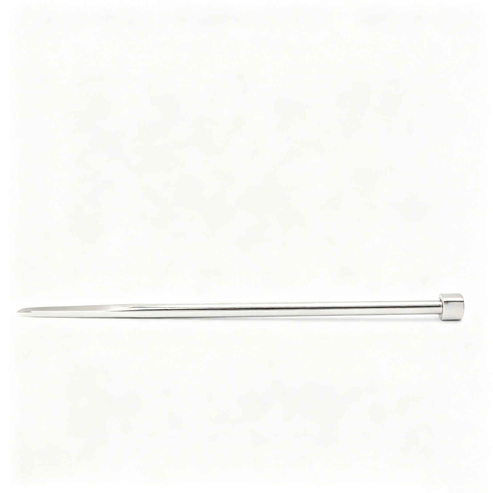



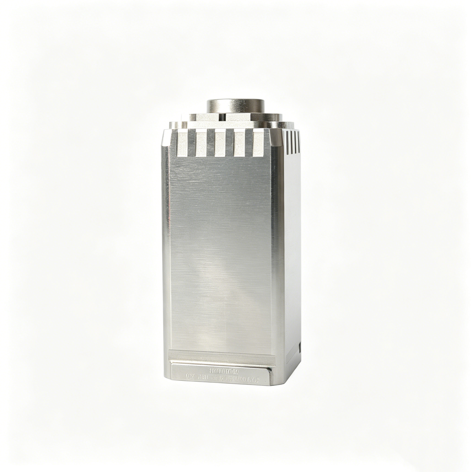



Related Configurable Component Families and RFQs






Aerospace Precision Parts Engineering Advantages
Drawing-led decisions that align manufacturability, critical features, inspection, and controlled revisions before production.
Drawing-First Review
We review drawings and models for critical dimensions, datums, surface requirements, material details, and application context before quotation discussions begin.
Practical DFM Input
DFM discussion identifies machining access, tolerance-stack risks, tool reach, feature sequencing, and realistic allowances before process commitments are made.
Coordinated Process Routes
CNC machining, EDM, grinding, and fitting are planned as connected operations when geometry, hardness, surface condition, or access requires it.
Critical Dimension Focus
Critical-to-quality features are identified with their datum strategy, measurement method, and inspection priorities to support clearer production decisions.
Inspection Plan Alignment
Inspection expectations are discussed early, including reporting needs, reference dimensions, surface checks, and documentation required for the specific order.
Revision Visibility
Drawing revisions, production questions, and delivery coordination remain visible throughout the project to help prevent uncontrolled changes and mismatched requirements.
Precision Parts and Tooling Families
Drawing-driven CNC, mold-component, connector-tooling and die-component work planned around critical dimensions, process access and inspection requirements.

CNC Machining Services
Precision CNC machining services for drawing-based parts that require a defined route through milling, turning, EDM, grinding and inspection. Share critical dimensions, material, quantity and application context so manufacturability and measurement expectations can be reviewed before quotation.
Upload a Drawing
CNC Milling
Custom CNC milling services for prismatic parts, cavities, pockets, features and mold details. Tool access, datum selection, wall geometry, corner radii and finishing allowances should be evaluated against the drawing before machining is planned.
Upload a Drawing
CNC Turning
Precision CNC turning services for shafts, pins, sleeves, bushings and other rotational components. Diameter tolerances, concentricity, thread requirements, surface condition and part holding strategy should be clarified with the RFQ.
Upload a Drawing
5-Axis Machining
5-axis CNC machining for complex geometry where multiple faces, angled features or restricted tool access affect the process route. A drawing and 3D model help assess setup reduction, cutter reach, datum control and inspection feasibility.
Upload a Drawing
Swiss & Micro Machining
Swiss machining and micro machining for small, slender or detail-dense components where support, runout and handling influence results. Review material condition, critical diameters, transitions, threads and inspection methods before committing to production.
Upload a Drawing
Wire & Sinker EDM
Wire EDM services and sinker EDM services for hardened details, sharp internal geometry, narrow slots, fine features and mold-tooling profiles. Electrode strategy, wire path, flushing conditions, recast-layer requirements and finishing expectations need project-specific review.
Upload a Drawing
Precision Grinding
Precision surface and profile grinding for dimensions and surfaces requiring controlled stock removal after machining or heat treatment. Define datum surfaces, flatness or profile needs, grinding allowance, material state and the intended inspection method.
Upload a Drawing
Mold Core Inserts & Mold Cavity Inserts
Precision mold core and cavity inserts made from customer drawings for configurable tooling assemblies. Cooling, shutoff geometry, steel selection, heat-treatment sequence, EDM requirements and critical mating dimensions should be addressed during DFM review.
Upload a Drawing
Ejector & Ejection Components
Ejector pins, sleeves and ejection components for mold systems where fit, movement and wear affect part release. Provide hole or bore requirements, hardness and surface needs, guiding arrangement, stroke context and related mating-part data.
Upload a Drawing
Core Pins, Guide & Locating Components
Core pins, guide pins and locating components manufactured to drawing-defined dimensions and fits. Functional datums, alignment relationships, wear surfaces, material and heat-treatment requirements should be reviewed together with the mating components.
Upload a Drawing
Slides, Lifters, Gates & Mold Accessories
Mold slides, lifters, gates and accessories for configurable mold mechanisms and flow-control details. Evaluate travel, shutoff faces, guide and wear conditions, tool access, steel condition and assembly interfaces before selecting a process route.
Upload a Drawing
Connector Mold Components
Precision connector mold components for high-detail tooling where cavity geometry, pin features, alignment and surface condition influence molding performance. Drawings should identify critical interfaces, material requirements, EDM or grinding needs and inspection priorities.
Upload a Drawing
Stamping Die Components
Precision stamping die components for punch, die, guide and forming applications. Material, hardness, edge condition, clearance relationships, wear areas and mating-component interfaces should be defined so machining, EDM and grinding can be planned responsibly.
Upload a Drawing
Injection, MIM, CIM & Overmolding Tooling
Injection mold components and tooling for MIM, CIM and overmolding applications within verified production scope. Submit the part geometry, resin or feedstock context, shrinkage assumptions, gate and vent requirements, mating assemblies and quality expectations for a practical review.
Upload a Drawing
Machining Materials
CNC machining materials selected against drawing requirements, functional loads, corrosion conditions, machinability and required downstream treatment. Confirm material grade, supply condition, traceability expectations and any heat-treatment sequence before production planning.
Upload a Drawing
Surface Finishes & Heat Treatment
Surface finishing and heat treatment planned around the component’s functional surfaces, dimensional risk and mating conditions. Specify required finish, coating or hardness, masked areas, post-treatment grinding stock and the acceptance or inspection criteria.
Upload a Drawing
Quality, Metrology & Documentation
Precision inspection, metrology and quality documentation aligned to the order and verified inspection plan. Identify critical-to-quality dimensions, datums, reporting format, sampling expectations, revision level and any traceability records needed before production begins.
Upload a Drawing
Prototyping & Low-Volume Production
Rapid prototyping and low-volume manufacturing for drawing-based validation, bridge demand and controlled iteration. Provide the latest revision, quantity range, material, critical dimensions, surface priorities, inspection needs and target delivery date for review.
Upload a DrawingMaterials for Aerospace Precision Parts

Aluminum Alloys
Lightweight machinable alloys for brackets, housings, and structural interfaces where mass, corrosion behavior, and surface treatment matter. Grade, temper, anodizing requirements, and critical datum features should be defined on the drawing before route selection.

Titanium Alloys
High-strength, corrosion-resistant options considered for demanding aerospace precision parts and weight-sensitive interfaces. Tool access, heat input, material condition, and inspection priorities require drawing-led review because machinability and finishing needs vary by alloy and geometry.

Stainless Steels
Corrosion-resistant steels suited to fittings, housings, shafts, and wear-prone components where strength and environmental exposure matter. Alloy grade, hardness condition, passivation expectations, and grinding allowance should be aligned with functional dimensions and mating requirements.

High-Strength Steels
Alloy and tool steels considered for loaded components, tooling elements, and precision interfaces requiring controlled hardness or wear resistance. Heat-treatment sequence, distortion risk, machining allowance, and final grinding strategy should be agreed before manufacturing begins.

Copper Alloys
Conductive copper alloys may suit electrical interfaces, thermal-management details, and specialized connector-related components. Material grade, conductivity needs, plating requirements, and burr-control criteria should be reviewed with the part geometry and inspection plan.
Aerospace Precision Parts Process Routes

CNC Milling
CNC milling establishes prismatic features, pockets, profiles and datum surfaces from the approved drawing. Tool access, clamping strategy and machining allowance are reviewed early to protect critical dimensions and leave suitable stock for downstream finishing.

CNC Turning
CNC turning produces rotational features such as shafts, pins, bores and concentric diameters. The route considers datum selection, runout requirements, material condition and whether later grinding or EDM is needed for final geometry.


Wire EDM
Wire EDM is considered for precise profiles, narrow slots, hardened features and shapes with limited conventional tool access. Wire path, start-hole location, corner requirements and recast-layer expectations should be agreed against the drawing.

Sinker EDM
Sinker EDM forms detailed cavities, deep ribs and internal features using planned electrodes. Electrode strategy, spark allowance, surface requirements and subsequent fitting or polishing needs are evaluated as part of the controlled process route.

Precision Grinding
Precision grinding refines critical flats, diameters and datum relationships after the relevant machining or heat-treatment stage. Grinding stock, distortion risk, surface specification and the inspection method are defined before final fitting and release.
Aerospace Precision Parts Tooling Features

Core Pins
Core pins form small internal features, holes and molded details. Selection should consider feature geometry, material condition, support length, EDM access, grinding requirements and replacement strategy defined by the approved drawing.

Guide Components
Guide pins, bushings and related elements establish repeatable mold alignment. Their fit, lubrication provisions, hardness requirements and wear interface should be reviewed with the plate layout, load path and specified running clearances.

Locating Features
Locating pins, keys and datum features control positional relationships between plates, inserts and mating tooling. Define functional datums, assembly sequence, tolerance stack and inspection method before releasing the manufacturing route.

Slides And Lifters
Slides and lifters address undercuts and angled release requirements in molding tooling. Review travel, interference, bearing surfaces, actuation method, machining access and fitting allowance against the approved assembly and operating conditions.

Gate Inserts
Gate inserts shape material entry and can affect fill behavior, wear and service access. Provide gate geometry, material, surface requirements and application context so the machining, EDM and finishing approach can be evaluated.
SUUXIANG for Aerospace Precision-Part Projects
SUUXIANG is the sole public-facing brand of Dongguan SuuXiang Precision Mold Co., Ltd., established in 2010 in Chang’an Town, Dongguan, Guangdong, China. Founded by legal representative XiaoCheng Huang, the company supports international engineering and sourcing teams with drawing-driven manufacturing for aerospace precision-part projects, custom machined parts, precision mold components, connector tooling and stamping-die components.
Our work begins with the drawing, 3D model, material requirement, quantity, application, and quality expectations. CNC milling and turning, multi-axis machining, EDM, precision grinding, fitting, and inspection are planned around critical dimensions, datum strategy, machining access, grinding stock, and practical inspection needs.
What distinguishes SUUXIANG is disciplined technical coordination before commitments are made. We use DFM discussion, revision control, process-route review, and inspection planning to keep manufacturing decisions visible. For aerospace precision parts, we assess the available evidence and requirements before confirming a workable production approach.

Aerospace Precision Parts: Core Capability Detail
DFM and Critical Dimensions
Each aerospace precision-part inquiry begins with the drawing, model, material, quantity and quality requirements. SUUXIANG reviews critical dimensions, datum relationships, surface requirements, tool access and revision status before defining a responsible quotation and manufacturing route.
- Identify critical-to-quality dimensions and functional datums
- Review tolerance stacks, access limits, and surface priorities
- Clarify material, heat-treatment, and delivery requirements
- Align revision control before production commitments

CNC and EDM Process Planning
Complex geometry may require more than one machining method. SUUXIANG plans the sequence across CNC milling or turning, multi-axis work, wire EDM, sinker EDM, and intermediate inspection, considering machining allowance, electrode strategy, wire path, and heat-treatment timing.
- Select processes around geometry and tolerance needs
- Plan electrode and wire-EDM access where required
- Preserve stock for subsequent grinding or finishing
- Review sequence risks before releasing the work order

Grinding and Precision Fitting
For mating interfaces, locating features, and high-priority surfaces, grinding and fitting are planned as controlled finishing steps rather than afterthoughts. The review considers datum transfer, grinding stock, hardness condition, assembly function, and the inspection method needed to verify the finished condition.
- Define grinding allowance from the process sequence
- Consider hardness and distortion before final finishing
- Review fit, location, and mating-component context
- Match final checks to functional feature priorities

Inspection and Traceability
Inspection expectations should be specified with the RFQ, especially for aerospace precision parts with defined critical features. SUUXIANG aligns the inspection plan and final documentation with the order, focusing on agreed dimensions, reporting needs, traceability information, and visible revision communication.
- Confirm dimensional and reporting requirements early
- Use agreed inspection methods for critical features
- Keep order revisions visible through coordination
- Provide documentation consistent with the verified inspection plan

How a Drawing-Led Review Differs From a Standard Quote Workflow
A drawing-led workflow built around manufacturability, critical dimensions, revisions, and inspection expectations.
← Swipe left or right to view →
Aerospace Precision Parts: Drawing-to-Inspection Process
A controlled sequence that keeps DFM decisions, critical dimensions, revision status and inspection expectations visible before shipment.
Review RFQ Package
We review drawings, models, material, quantity, application context, delivery target and reporting requirements, identifying missing information before quotation or production planning begins.
Confirm DFM and Datums
The team evaluates critical dimensions, datum strategy, tolerance stack, tool access, heat-treatment sequence and process risks, then aligns the proposed route with your requirements.
Plan Manufacturing Route
CNC machining, EDM, grinding, fitting and intermediate inspection are sequenced around geometry, surface requirements, machining allowance and applicable aerospace precision parts priorities.
Machine Critical Features
Production follows the approved drawing revision, using the selected machining and EDM strategy while maintaining visibility of material, process decisions and revision-controlled information.
Inspect, Pack and Coordinate
Final inspection follows the agreed plan; documentation, protective packing and delivery coordination are matched to the order before aerospace precision parts are released.
How to Source Aerospace Precision Parts
Provide complete technical inputs early so SUUXIANG can align DFM review, process planning, inspection expectations, and revision control before production release.
Upload Your Technical Package
Send the 2D drawing, available 3D model, application context, and identified critical dimensions so the team can review datums, access, and feature intent.
Confirm Production Requirements
Specify material, heat treatment, quantity, surface requirements, target delivery date, inspection reports, and any mating-component constraints that affect the proposed manufacturing route.
Review DFM and Quote
Evaluate the DFM feedback, machining and EDM or grinding approach, quality plan, quotation, and any sampling recommendation before confirming the controlled revision.
Release Approved Production
Approve the final technical and commercial details to begin coordinated machining, inspection, and delivery updates aligned with the agreed drawing revision and verification requirements.
Aerospace Precision Parts Documentation and Verification

Aerospace Precision Parts: Verified Customer Outcomes
Approved customer case summary pending. Publish only after the customer confirms the project scope, measurable outcome, and permission to attribute the statement.
Approved customer case summary pending. Add the verified drawing revision, inspection result, delivery outcome, and customer-approved wording before this testimonial is published.
Approved customer case summary pending. Include only substantiated results, such as inspected quantities, dimensional findings, or revision-cycle outcomes, after customer approval is documented.
Aerospace Precision Parts FAQ
Practical answers for teams preparing a drawing-led RFQ, from technical review through inspection and delivery planning.
Can SUUXIANG quote low-volume aerospace precision parts?
What files do you need to quote aerospace precision parts?
How should I specify tolerances for aerospace precision parts?
Can you provide samples or first-article parts before a larger order?
How are material and heat-treatment requirements handled?
How do you plan lead time for drawing-based CNC parts?
What inspection reports can be requested with an order?
How are shipping and drawing confidentiality handled?
The Complete Buyer’s Guide to aerospace precision parts
Use this decision framework to define requirements, compare manufacturing and quality criteria, control sourcing risk, and avoid the documentation, cost, and supplier-selection mistakes that can delay aerospace programs.
1. What Are aerospace precision parts?
2D drawings, 3D models, material callouts, and inspection requirements define aerospace precision parts: components made to a controlled specification for flight, space, ground-support, or aerospace-adjacent systems. Their significance comes from how a feature functions within an assembly, not simply from whether it was CNC machined.
5 linked controls—dimensional conformance, material and heat-treatment integrity, repeatable process execution, traceable records, and application-risk review—determine whether a part is suitable for its stated use. A correct nominal size is insufficient when datum relationships, surface condition, lot identity, or revision status cannot be demonstrated.
3 sourcing categories should remain distinct: prototypes support fit, form, and early design learning; non-flight-critical parts may serve fixtures, test equipment, or ground-support applications; flight-critical parts require customer-defined qualification, documentation, and approval pathways. SUUXIANG can review drawings for manufacturability and inspected custom manufacturing within its verified scope, while buyers should confirm category-specific requirements before release.
2. Evolution of Aerospace Precision Manufacturing
5-axis CNC machining combines linear and rotary motion, reducing setups needed to reach compound angles, pockets, and intersecting features. For aerospace precision parts, fewer re-clamps can simplify datum control when lightweight alloys or thin-wall geometries are susceptible to distortion.
3D digital inspection has shifted verification from isolated hand-measured dimensions toward recorded coordinate, scan, and reportable measurement results. The essential change is not automation alone: inspection plans must still identify critical features, datum alignment, measurement method, acceptance criteria, and the drawing revision being verified.
1 additive-assisted development route can produce or evaluate a complex form before committing to full subtractive machining, while CNC, EDM, and grinding remain relevant for controlled interfaces and finish-critical features. Shorter iteration cycles raise the documentation bar: retain material records, process sequence, inspection evidence, nonconformance disposition, and revision-controlled communication matched to the purchase order.
3. Types of aerospace precision parts
Six drawing families cover most aerospace precision parts RFQs. Classify the part by load path, environment, interfaces, and evidence required before asking a supplier to select a route.
Structural Brackets And Fittings
Structural brackets and fittings commonly combine prismatic pockets, fastener patterns, and datum faces. Load transfer, burrs, distortion, and hole-position stack-up drive CNC milling, drilling, deburring, and inspection questions.
Ask which faces locate the assembly, which holes are critical, and whether formed features or post-machining are required.
Engine, Thermal, And Fluid Parts
Engine and thermal-system components may use thin walls, bores, sealing lands, or heat-transfer passages. Temperature exposure, leakage, concentricity, and tool access can require turning, multi-axis milling, EDM, grinding, and controlled inspection.
Fluid and hydraulic fittings add threads, ports, and mating seals. Specify pressure-related interfaces, thread standard, surface condition, and cleaning expectations.
Avionics, Landing, And Development Parts
Avionics and connector housings use cavities, pin locations, shielding interfaces, and tight mating datums. Pin alignment, wall thickness, burr control, and finish compatibility should guide milling, micro machining, EDM, and inspection planning.
Landing-system hardware and tooling prototypes can combine high-load bores, wear faces, guide features, and revision-sensitive geometry. Identify safety-critical features, heat-treatment sequence, prototype quantity, and required reports before SUUXIANG reviews the drawing.
4. Materials for aerospace precision parts
Five material families create different weight, temperature, and process constraints. For aerospace precision parts, selection follows the approved drawing, application, and qualification requirements; suppliers should not substitute material.
| Family | Weight/Strength | Heat/Corrosion | Machining/Finish | Evidence |
|---|---|---|---|---|
| Aluminum | Low/medium | Moderate/grade-dependent | Good/anodize | Cert, temper |
| Titanium | Low/high | High/strong | Difficult/specialist | Cert, heat lot |
| Stainless/nickel | High/high | High/strong | Tough/passivate | Cert, melt lot |
| Polymers | Very low/lower | Grade-dependent | Easy/limited | Resin trace |
| Composite specialties | Low/variable | Interface-dependent | Controlled/compatible | Laminate trace |
Metal Alloy Trade-Offs
7075 and 2024 support weight-conscious comparisons. Temper and corrosion environment remain drawing-controlled.
Titanium and nickel grades change cutting behavior. Heat exposure and section geometry drive review.
Polymers And Composite Interfaces
PEEK and PEI need grade-specific temperature review. Filled compounds can change machining and finish behavior.
CFRP-interface hardware needs galvanic and sealing consideration. Laminate, adhesive, or insert requirements govern.
Documentation Before Release
2D drawing callouts should identify grade, condition, and traceability. Required heat, melt, or resin records belong in the RFQ.
AS9102 forms may be contractually specified. Inspection evidence cannot validate an unapproved substitution.
5. Finishes, Marking, and Customization Options
Three finish decisions—corrosion resistance, electrical behavior, and dimensional change—should be resolved before release. For aerospace precision parts, a finish is a controlled requirement, not a quotation afterthought.
| Option | Primary Effect | Drawing Or PO Requirement |
|---|---|---|
| Anodizing | Corrosion protection; dimensional buildup | Type, color, thickness, masking |
| Passivation | Surface contamination removal | Material grade and governing specification |
| Plating | Conductivity or corrosion protection | Deposit, thickness, adhesion requirement |
| Conversion coating | Corrosion protection or paint base | Process class, coverage, masking |
| Bead blasting | Matte appearance and texture | Media, finish area, cosmetic criteria |
Functional Versus Cosmetic Finishes
Anodizing, passivation, plating, and conversion coatings serve different functions: corrosion protection, conductivity, paint adhesion, or appearance. Bead blasting changes visual texture and can obscure a surface-condition requirement.
Functional finishes need a specified standard, class or type, thickness, masking, and post-process dimensional limits. Cosmetic requests should separately define color, texture, acceptable variation, and viewing criteria.
Heat Treatment And Inserts
Heat treatment can change size, hardness, distortion risk, and the machining sequence. The drawing should identify material condition, required hardness range, test method, and which dimensions are finished after treatment.
Threaded inserts require insert type, material, installation method, location datum, pullout or torque requirement when applicable, and inspection evidence. SUUXIANG should confirm the proposed sequence during drawing review.
Marking And Packaging
Laser marking must define content, character height, location, orientation, contrast requirement, and prohibited surfaces. Part number, revision, lot identifier, and serialization rules must agree across the drawing, purchase order, and traceability plan.
Controlled packaging should state cleanliness, corrosion inhibitor, individual separation, orientation, labeling, and damage-sensitive features. Inspection criteria must cover finish coverage, thickness where specified, marking legibility, and packaging condition.
6. Construction and Quality Control Elements
A drawing should identify the few features that control fit, load path, sealing, or alignment. For aerospace precision parts, buildability begins with unambiguous datums, tolerances, and a measurable acceptance plan.
Datums And Feature Control
Three datum features can establish a repeatable inspection frame for location, orientation, and runout. Apply GD&T only where function requires it; a positional tolerance without datum precedence cannot be verified consistently.
- Identify critical-to-function holes, bores, and faces
- Specify profile where geometry governs fit
- Define thread class and full engagement
Machining-Ready Geometry
0.2 mm-radius internal corners may require small tools, longer cycles, or EDM; confirm tool access before release. State surface finish, edge-break limits, minimum wall thickness, burr direction, and grinding allowance on the drawing.
Inspection And Containment
First-article inspection compares initial production against the drawing and agreed ballooned dimensions. In-process checks, calibrated gauges, and documented nonconformance disposition help prevent an unreviewed deviation from reaching assembly.
- Match method to feature: CMM, micrometer, pin gauge
- Record revision, measurement result, and inspector
- Segregate nonconforming parts pending disposition
7. Choosing an aerospace precision parts manufacturer
Two questions should guide selection: can the supplier demonstrate the required process route, and can it document each controlled step? For aerospace precision parts, capability claims should be tested against the released drawing, not a generic equipment list.
| Evaluation Area | Request | Decision Signal |
|---|---|---|
| Process fit | Route and comparable geometry | Drawing-specific constraints identified |
| Material control | Certificate and lot traceability | Records link material to order |
| Quality scope | Inspection plan and sample report | Methods cover critical features |
| Capacity | Schedule assumptions and dependencies | Lead time is explained |
Request Project Evidence
Before award, request a drawing-review response identifying datums, critical dimensions, tool access, heat-treatment sequence, and proposed inspection method.
One representative sample report is more useful than broad tolerance claims; confirm its part family, revision, material condition, and measurement equipment.
- Material certificate format and lot linkage
- First-article inspection scope
- Revision-control and nonconformance workflow
Test Delivery And Data Controls
Three delivery questions expose planning realism: available machine time, outside-process dependencies, and inspection capacity at the requested quantity.
Where export-controlled or customer-restricted data applies, define permitted access, file-transfer method, retention, and subcontractor disclosure before transmitting technical packages.
8. Common Aerospace Sourcing Mistakes
Aerospace sourcing failures usually begin before the first setup. Engineering, procurement, and quality should jointly define the controlled technical package and evidence required for aerospace precision parts.
Control The Drawing Package
2D drawings without complete datums, tolerances, material, and finish callouts force assumptions that can produce nonconforming parts.
100% of critical features should identify datum references, limits, material condition, coating or finish, and applicable notes before quotation.
Use DFM Before Award
DFM feedback ignored on tool access, thin walls, EDM strategy, or grinding allowance can add rework, schedule risk, and unstable dimensions.
Unit-price-only selection can omit process controls or communication needed for the requirement. Compare quoted scope, manufacturing route, exceptions, and delivery assumptions alongside price.
Specify Verification And Changes
Inspection scope omitted from the RFQ leaves uncertainty over sampling, critical dimensions, reporting, and traceability. Define the inspection method, report format, and acceptance evidence with the quality team.
Revision changes sent informally, or prototypes released without a production handoff, create mixed configurations. Issue controlled revisions, record deviations, and review prototype results before locking the production package.
9. Steps to Launch a Precision Parts Project
A controlled launch turns a drawing package into an agreed manufacturing and inspection path. For aerospace precision parts, freeze requirements before material is cut and record every decision against a revision.
Prepare The Controlled Package
At Step 1, provide the released 2D drawing, available 3D model, quantity, material, heat treatment, finish, and target date. Identify critical dimensions, datums, mating context, inspection reports, and confidentiality requirements.
At Revision A, state which file governs if model and drawing differ. Document approved deviation routes and the buyer’s technical contact.
Close DFM And Quotation
At Step 2, review tool access, tolerance stack, machining allowance, EDM or grinding strategy, and inspection method. Resolve ambiguous callouts before quotation acceptance.
At Step 3, compare quotations on process route, included inspection, material evidence, lead-time assumptions, and exclusions. Record the selected scope rather than comparing unit price alone.
Approve And Control Release
At Step 4, approve a sample or first article against the released drawing and agreed measurement plan. Capture any concession, rework limit, or acceptance criterion in writing.
At Step 5, use a pilot build to confirm packaging, traceability, delivery communication, and repeatability before production release. Route every later change through a dated revision notice.
10. Aerospace Precision Parts Pricing and Lead Times
Three commercial inputs usually dominate an aerospace precision parts quotation: the specified material grade and its availability, total machine and setup time, and geometry requiring multi-axis access, EDM, or grinding. Tight tolerances, datum-dependent features, and controlled surface requirements can add programming, fixturing, in-process checks, and slower finishing passes.
Two documentation decisions can materially change both cost and schedule: the inspection plan and the traceability package. First-piece records, dimensional reports, material certificates, revision-controlled documentation, protective packaging, and special labeling should be defined before release rather than added after machining begins.
One approved drawing package is the basis for a usable quotation. SUUXIANG should confirm material, heat treatment, quantity, inspection scope, finishing, packaging, delivery destination, and revision status; the ranges below are illustrative only, not commitments.
| Quantity tier | Typical cost-driver profile | Illustrative lead-time range |
|---|---|---|
| 1–5 pieces | Setup, programming, material sourcing, first-piece inspection | 2–5 weeks |
| 6–50 pieces | Machine time, tolerance control, inspection sampling | 3–7 weeks |
| 51+ pieces | Repeatable fixturing, material releases, packaging and documentation | 4–10 weeks |
Upload Your Aerospace Precision Parts Drawing for Review
Include material, quantity, quality priorities, delivery target, and inspection needs so our team can assess the drawing and prepare a technical quote.