
Energy Equipment Components, From Drawing to Inspection
SUUXIANG plans CNC machining, EDM, grinding and inspection for energy equipment components with critical dimensions, revision control and RFQ requirements reviewed early.
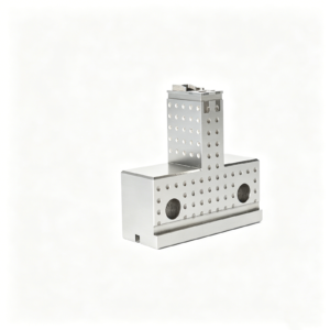
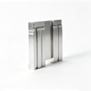
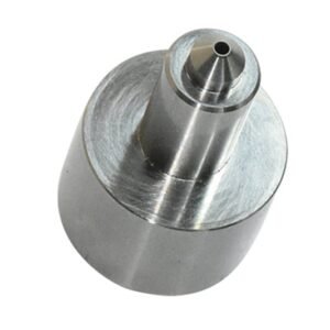
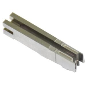
Representative Precision Components and Tooling


Drawing-Based Component Families and Quotation




Why Teams Choose SUUXIANG for Energy Equipment Components
Drawing-driven manufacturing support focused on manufacturability, critical dimensions, process planning, inspection evidence, and controlled revisions.
Drawing-Led DFM Review
Review drawings, models, material requirements, and application context before quotation to identify machining access, datum, and tolerance risks.
Planned Process Routes
Select appropriate CNC, EDM, grinding, fitting, and inspection steps around geometry, material condition, surface requirements, and production priorities.
Critical Dimensions First
Focus discussion on critical-to-quality features, tolerance stacks, mating relationships, and datum strategy before manufacturing commitments are made.
Inspection Aligned to Requirements
Define inspection methods and reporting expectations against the drawing, critical features, and agreed quality plan for each order.
Visible Revision Control
Keep drawing revisions, production changes, and delivery coordination visible so engineering, sourcing, and quality teams can make informed decisions.
Energy Equipment Components and Precision Tooling
Drawing-driven component families for energy-equipment programs, planned around critical dimensions, process route, inspection requirements, and controlled revisions.

CNC Machining Services
Precision CNC machining services for drawing-based energy-equipment parts where material, datums, critical dimensions, surface requirements, and inspection expectations must be reviewed before a process route and quotation are established.
Upload a Drawing
CNC Milling
Custom CNC milling services for prismatic housings, plates, manifolds, brackets, and tooling details. Machining access, clamping strategy, wall sections, tolerances, and later finishing or inspection requirements are reviewed against the supplied drawing.
Upload a Drawing
CNC Turning
Precision CNC turning services for shafts, bushings, sleeves, pins, threaded features, and rotational components. SUUXIANG evaluates datum selection, concentricity, runout, material condition, and secondary machining needs before production planning.
Upload a Drawing
5-Axis Machining
5-axis CNC machining supports complex geometry that benefits from reduced setups and improved feature access. The route is assessed against tool reach, fixture stability, tolerance relationships, surface requirements, and practical inspection access.
Upload a Drawing
Swiss & Micro Machining
Swiss machining and micro machining support small, detailed turned components where feature sequence, material behavior, concentricity, burr control, and measurement method directly affect manufacturability and inspection planning.
Upload a Drawing
Wire & Sinker EDM
Wire EDM and sinker EDM services support hardened details, narrow slots, internal geometry, sharp-feature requirements, and complex cavity work. Electrode strategy, wire path, EDM allowance, recast considerations, and finishing steps are defined with the drawing review.
Upload a Drawing
Precision Grinding
Precision surface and profile grinding is used where flatness, parallelism, profile accuracy, fit, or surface condition requires controlled stock removal. Grinding allowance, heat-treatment sequence, datum condition, and inspection method should be agreed in advance.
Upload a Drawing
Mold Core & Cavity Inserts
Precision mold core and cavity inserts are configured from the part design, resin or process context, material requirement, cooling or feature needs, and dimensional priorities. CNC, EDM, grinding, fitting, and inspection are planned as an integrated route.
Upload a Drawing
Ejector & Ejection Components
Ejector pins, sleeves, and ejection components are evaluated for fit, guidance, wear conditions, material and heat treatment, surface needs, and mating-part relationships. Drawings should identify critical diameters, working lengths, and applicable inspection requirements.
Upload a Drawing
Core Pins, Guide & Locating Components
Core pins, guide pins, and locating components require controlled relationships to mating features. SUUXIANG reviews datum strategy, fit class, wear considerations, heat-treatment sequence, grinding stock, and inspection points before manufacturing.
Upload a Drawing
Slides, Lifters, Gates & Mold Accessories
Mold slides, lifters, gates, and accessories are supplied as configurable tooling components rather than assumed stock items. Motion interfaces, shutoff geometry, fit, material treatment, machining access, and assembly context inform the production route.
Upload a Drawing
Connector Mold Components
Precision connector mold components support fine-pitch and high-repeatability tooling requirements. Buyers should provide part geometry, mating details, critical dimensions, material and treatment requirements, EDM needs, and inspection or documentation expectations.
Upload a Drawing
Stamping Die Components
Precision stamping die components are planned around strip direction, forming or cutting function, material condition, clearance relationships, wear surfaces, and assembly datums. CNC, EDM, grinding, fitting, and inspection are selected to suit the verified design.
Upload a Drawing
Injection, MIM, CIM & Overmolding Tooling
Injection, MIM, CIM, and overmolding tooling work is considered within verified production scope. Drawing review addresses material flow context, tooling geometry, inserts, shutoffs, tolerance priorities, surface requirements, and the required manufacturing evidence.
Upload a Drawing
Machining Materials
CNC machining materials are selected from the drawing and application requirements, not a generic catalog. Material grade, condition, traceability needs, corrosion or wear environment, heat-treatment requirements, and compatibility with the planned process should be specified.
Upload a Drawing
Surface Finishes & Heat Treatment
Surface finishing and heat treatment are coordinated with dimensional priorities and the manufacturing sequence. Buyers should identify required finish, hardness or treatment condition, masking needs, critical surfaces, post-treatment grinding allowance, and documentation expectations.
Upload a Drawing
Quality, Metrology & Documentation
Precision inspection, metrology, and quality documentation are aligned to the order and verified inspection plan. Define critical dimensions, datum references, sampling or reporting expectations, material evidence, revision status, and any required traceability before production begins.
Upload a Drawing
Prototyping & Low-Volume Production
Rapid prototyping and low-volume manufacturing support drawing-based validation, tooling development, and controlled program changes. Quantity, material, quality priorities, delivery target, revision level, and inspection needs help determine a practical production route.
Upload a DrawingEnergy Equipment Components: Materials Selected for Controlled Manufacturing

Alloy Tool Steel
Used for high-load mold inserts, forming details and wear interfaces. Heat treatment and grinding stock must be planned together, because hardness and final geometry can affect machining sequence and inspection strategy.

Stainless Steel
Specified for corrosion-sensitive energy equipment components, fluid-contact features and external hardware. Grade selection should consider corrosion exposure, weld or assembly interfaces, and the machining behavior required by the drawing.

Carbon Steel
A practical option for structural brackets, shafts, fixtures and general machine details where the application permits. Material condition, coating requirements and any post-machining heat treatment should be defined before quotation.

Aluminum Alloys
Common for lightweight housings, covers, thermal-management parts and prototype assemblies. Alloy and temper influence machinability, thread design and dimensional stability, particularly where thin walls or tight datum relationships are specified.

Copper Alloys
Considered for conductive inserts, electrical interfaces and specialized thermal-transfer features. Copper alloy choice affects cutting behavior, surface condition and inspection planning, so functional conductivity and dimensional priorities should accompany the RFQ.
Energy Equipment Components: Precision Process Routes

CNC Milling
CNC milling forms prismatic features, pockets, faces, and complex multi-axis geometry in energy equipment components. Tool access, datum references, and remaining stock are reviewed to support controlled dimensions and suitable downstream finishing.

CNC Turning
CNC turning produces concentric diameters, bores, threads, sealing features, and rotational profiles. It supports efficient control of roundness-related geometry when the drawing defines functional datums, surface priorities, and mating-part requirements.

Sinker EDM
Sinker EDM creates deep cavities, sharp internal details, and difficult-to-reach geometry where cutting tools have limited access. Electrode strategy, spark allowance, and finish expectations are planned around the specified material and heat-treatment condition.

Wire EDM
Wire EDM cuts accurate profiles, narrow slots, and hardened features without conventional cutting forces. Wire path, start-hole access, corner requirements, and datum strategy should be established to manage geometry and inspection requirements.

Precision Grinding
Precision grinding refines critical faces, diameters, and functional fits after machining or heat treatment. Grinding stock, clamping approach, surface requirement, and measurement method are reviewed to protect dimensional relationships and usable finish.

Fitting and Inspection
Fitting and inspection verify functional relationships between precision parts, including mating surfaces, movement, and critical dimensions. The work follows the agreed drawing revision and inspection plan, with required reporting aligned to the order.
Energy Equipment Components: Tooling Features and Accessories

Guide Locating Parts
Guide pillars, bushings, dowels, and locating features help establish repeatable alignment between tooling elements. Define datum relationships, fits, material, and wear considerations so machining and inspection methods reflect the intended assembly function.

Ejector Elements
Ejector pins, sleeves, blades, and related retention features support controlled part release in applicable tooling. Provide pin locations, clearance requirements, surface expectations, and mating details for a practical machining, EDM, grinding, and fitting review.

Gates and Runners
Drawing-defined gates, runners, and feed features affect flow, part separation, and tool serviceability. Their geometry should be reviewed with machining access, EDM strategy, polish requirements, and the relevant molding or overmolding application context.

Slides and Lifters
Slides, lifters, and related moving inserts accommodate undercuts or complex release paths where the tooling design requires them. Specify travel, interface geometry, critical clearances, surface treatment requirements, and fitting expectations before production planning.

Traceability Marking
Part marking, cavity identification, revision labels, and inspection references can be incorporated as drawing-defined requirements. Confirm marking location, method, legibility, and documentation needs to preserve traceability without compromising critical functional surfaces.
About SUUXIANG Energy Equipment Components
SUUXIANG is the sole public-facing brand of Dongguan SuuXiang Precision Mold Co., Ltd., established in 2010 in Chang’an Town, Dongguan, Guangdong, China. Founded by XiaoCheng Huang, the company helps international engineering, sourcing, and quality teams convert drawings and specifications into inspected custom parts, precision mold components, connector tooling, and energy equipment components.
Our process planning brings CNC milling and turning, multi-axis machining, wire and sinker EDM, precision grinding, fitting and inspection into a controlled manufacturing workflow. Before quotation or production commitments, we review DFM, critical dimensions, datums, machining access, material and heat-treatment requirements, and inspection expectations.
What differentiates SUUXIANG is disciplined coordination around the drawing: revision control, process-route decisions, machining allowances and inspection documentation remain visible throughout the project. We assess each request against verified production scope, then work with buyers to define the evidence, quality requirements and delivery priorities needed for a responsible RFQ.

Energy Equipment Components Built Through Controlled Precision
DFM Starts With Datums
Before quotation or production planning, SUUXIANG reviews the drawing, model, critical dimensions, datum scheme, tolerances, material requirements and machining access. This establishes a practical route for energy equipment components and identifies questions that require resolution before commitments are made.
- Confirm critical-to-quality dimensions and datum relationships
- Review tolerance stack and accessible cutting directions
- Identify material, heat-treatment and surface requirements
- Flag missing inputs before process planning

CNC and EDM Process Planning
Complex geometry may require a coordinated sequence of CNC milling, turning, multi-axis machining, wire EDM or sinker EDM. SUUXIANG plans each route around feature access, electrode needs, wire paths, heat-treatment timing and the dimensions that must remain controlled.
- Match machining methods to feature geometry
- Plan electrode strategy for inaccessible internal details
- Assess wire paths, corner conditions and cut sequence
- Sequence machining around heat treatment when required

Grinding and Fitting Strategy
Where functional surfaces, guided movement or close mating relationships are specified, grinding allowance and fitting requirements must be considered early. SUUXIANG coordinates stock condition, finishing access and mating-part context so the planned process supports the drawing’s functional intent.
- Define grinding stock before final machining stages
- Review functional surfaces and locating relationships
- Consider fit requirements with mating components
- Keep finishing steps aligned to critical dimensions

Inspection and Revision Visibility
Production control extends beyond machining. SUUXIANG aligns inspection methods and required reporting with the order’s verified plan, while maintaining visible revision and delivery coordination. This gives sourcing and quality teams a clearer basis for reviewing energy equipment components before shipment.
- Align inspection points with critical drawing features
- Clarify requested reports and acceptance evidence
- Maintain revision control through production coordination
- Confirm delivery requirements before final release

Energy Equipment Components Need a Drawing-Driven Partner
Compare a documented engineering workflow with typical generic quotation approaches.
← Swipe left or right to view →
Energy Equipment Components: From RFQ to Delivery
A drawing-driven sequence that keeps manufacturability, critical dimensions, revision control and inspection expectations visible before and throughout production.
Review Drawings and Requirements
We review 2D drawings, 3D models, material, quantity, application context, target date, and quality requirements to identify critical dimensions and open technical questions.
Confirm DFM and Process Route
The team evaluates datum strategy, tolerance stack, tool access, machining allowance, heat-treatment sequence, and EDM or grinding needs before quotation and production planning.
Machine Critical Part Features
Approved work proceeds through the suitable CNC milling, turning, multi-axis, Swiss, or micro-machining route, with revision information maintained against the production requirements.
Apply EDM and Grinding
Where required, wire EDM, sinker EDM, precision grinding, and fitting are coordinated to achieve specified geometry, surface requirements, functional interfaces, and controlled finishing allowances.
Inspect Pack and Coordinate Delivery
Parts are inspected against the agreed plan, documented as required by the order, protected for shipment, and coordinated with the customer’s delivery and traceability expectations.
How to Source Energy Equipment Components
Move from RFQ inputs to controlled production through a practical review process built around drawings, critical dimensions, and inspection requirements.
Submit Your Drawing Package
Provide the 2D drawing, 3D model when available, application context, material specification, quantity, target delivery date, and relevant mating-component information.
Define Critical Requirements
Identify critical dimensions, datums, tolerances, surface requirements, heat treatment, inspection reports, and any quality documentation needed for your energy equipment components.
Review DFM and Quotation
Review manufacturability, machining access, EDM or grinding needs, process sequence, inspection approach, revision status, commercial scope, and quotation assumptions before commitment.
Approve Samples When Needed
For suitable projects, evaluate sample parts against agreed dimensions, functional interfaces, surface expectations, and inspection evidence before authorizing the production release.
Release Controlled Production
After approval, SUUXIANG coordinates the confirmed machining, EDM, grinding, fitting, inspection, revision control, and delivery documentation according to the verified order plan.
Customer Case Studies Pending Approval

Energy Equipment Components: Verified Customer Outcomes
Approved customer case study pending. Publish only after the customer confirms the project scope, drawing revision, inspection evidence, delivery record, and measurable outcome.
Approved customer case study pending. Document the specific energy equipment components supplied, the agreed critical dimensions, quantity, inspection method, and the customer-approved project result before publication.
Approved customer case study pending. Use a verified customer statement only when the name, role, company, quotation context, and any reported performance or delivery figure are authorized for publication.
Buyer’s Guide to Energy Equipment Components
Practical RFQ, production-planning, inspection and revision-control guidance for drawing-driven custom parts.
What drawings are needed to quote energy equipment components?
Can you make energy equipment components from a sample or incomplete drawing?
What is the minimum order quantity for custom energy equipment components?
How should I plan lead time for CNC-machined or EDM parts?
What material and heat-treatment information should an RFQ include?
Can SUUXIANG provide inspection reports with energy equipment components?
How are shipping, packaging and delivery requirements handled?
How do you protect drawings and control design revisions?
The Complete Buyer’s Guide to energy equipment components
Use this decision framework to specify DFM-ready parts, compare supplier capabilities and quality controls, evaluate cost and lead-time drivers, and avoid sourcing mistakes that can delay energy-equipment programs.
1. What Are energy equipment components?
2010 is the founding year of Dongguan SuuXiang Precision Mold Co., Ltd.; in this guide, energy equipment components means the drawing-defined parts used within energy-related equipment—not complete turbines, battery systems, inverters, or power plants. The term covers parts whose geometry, material, tolerances, surfaces, and inspection requirements are controlled by an engineering specification.
2 sourcing categories should be kept separate. Standard purchased items—catalog fasteners, bearings, connectors, seals, sensors, and approved electrical assemblies—are normally sourced by part number and supplier qualification; custom components are sourced from a 2D drawing, 3D model, revision, and quality plan.
4 common application areas are solar and storage enclosures, power-conversion equipment, charging equipment, and production tooling for electrical or connector products. The custom scope may include CNC-machined housings, precision pins, locating features, mold inserts, connector-tooling parts, and stamping-die components when the stated requirement fits the manufacturing scope.
1 buyer question comes first: which item needs a controlled manufactured geometry rather than a catalog specification? Define its mating interfaces, critical dimensions, datum scheme, material and treatment condition, quantity, and inspection evidence before requesting a quotation.
2. Evolution of energy equipment components
Three operating contexts—conventional generation, electrified equipment, and renewable or storage systems—have broadened the sourcing brief for energy equipment components. Parts once specified mainly for structural fit or basic electrical function may now face vibration, thermal cycling, sealing interfaces, corrosive exposure, or repeated service access.
Two design pressures commonly arrive together: higher connector density and more constrained heat paths. This raises the importance of datum selection, positional control, burr limits, surface-contact requirements, and machining access; a tolerance that looks acceptable on an isolated drawing can still obstruct assembly or thermal transfer.
2010 is SUUXIANG’s founding year, and its drawing-led workflow reflects the procurement discipline now needed: define critical dimensions, material and heat-treatment requirements, revision status, inspection method, and mating-part context before route selection. Early DFM review can identify where CNC, EDM, grinding, fitting, and inspection evidence are appropriate, rather than treating manufacture as a later quotation detail.
3. Types of energy equipment components
Five custom part families cover most energy equipment components sourcing decisions. Selection begins with the function, critical datum scheme, mating interfaces, quantity, and inspection evidence required.
| Category | Typical Function | Drawing Inputs | Process And Selection |
|---|---|---|---|
| CNC mechanical parts | Mount or transfer loads | Datums, threads, fits | Mill, turn, grind; assess access |
| Connector tooling | Form or locate contacts | Contact geometry, burr limits | EDM, grinding; assess mating |
| Mold components | Shape insulating parts | Parting line, gates, cooling | CNC, EDM; assess resin and wear |
| Stamping-die parts | Blank or form metal | Strip layout, clearance | Wire EDM, grinding; assess stock |
| Prototype assemblies | Verify interfaces | BOM, models, inspection | Machining and fitting; assess revision control |
Mechanical Load Paths
1. CNC brackets, housings, shafts, and cooling interfaces carry loads or locate assemblies. Specify datums, threads, tolerances, and accessible tool paths before selecting milling, turning, or grinding.
Electrical Interface Tooling

2. Connector and contact-tooling parts form, locate, or inspect conductive interfaces. Provide contact geometry, insertion direction, mating context, burr limits, and electrode or wire-path constraints.
Tooling And Pilot Builds
3. Mold and stamping-die components support repeatable forming; prototype assemblies validate interfaces at low volume. Release revision-controlled drawings, material condition, assembly sequence, and inspection plan together.
4. Materials for energy equipment components
Material choice for energy equipment components begins with load, current path, fluids, temperature, and assembly. The drawing should state the material standard, condition, and any mandatory compliance evidence before quotation.
| Family | Strength | Conductivity | Corrosion/Temperature | Machining/Finish |
|---|---|---|---|---|
| Aluminum alloys | Medium | Moderate | Good / moderate | Good; anodize |
| Stainless steels | Medium-high | Low | High / high | Moderate; passivate |
| Copper alloys | Medium | High | Variable / moderate | Moderate; plate |
| Engineering plastics | Low-medium | Low | Grade-dependent | Good; limited finishing |
| Tool steels | High | Low | Needs protection / high | Hard machining; grind |
Material Trade-Offs
6061 aluminum reduces mass and accepts anodizing; stainless steels better resist wet or corrosive service. Copper alloys carry current and heat efficiently but can complicate machining and joining.
Selection By Interface
300-series stainless suits welded or fastened enclosures, while copper interfaces need plating and galvanic-corrosion review. Tight bores, threads, and flatness requirements may favor stable stock, grinding allowance, or a revised datum scheme.
Temperature And Compliance
Tool steels apply to wear-loaded tooling rather than ordinary housings; heat treatment must precede final tolerance planning. Engineering plastics require temperature, creep, chemical, flame, and electrical requirements to be specified by grade.
5. Customization and finishing options
2D drawings and 3D models should define geometry, thread standards, insert locations, surface texture, datums, and revision level before routing. For energy equipment components, each finish callout must identify the functional requirement, not merely color.
| Finish | Primary Function | Drawing Or Inspection Impact |
|---|---|---|
| Anodizing | Corrosion and appearance | Account for growth and masked areas |
| Plating | Conductivity or corrosion | Specify thickness and thread limits |
| Passivation | Stainless steel corrosion resistance | Define material and verification |
| Laser marking | Identification | Set location, content, and contrast |
Translate Drawing Requirements
ISO metric or Unified threads need class, engagement depth, and post-finish gauge requirement. Press-fit inserts require material, installation stage, and positional datum.
Ra callouts need a measurement location and direction; unspecified cosmetic texture can create unnecessary machining time.
Specify Functional Finishes
Anodizing, plating, passivation, and coatings serve different corrosion, conductivity, wear, or chemical-exposure needs. Laser marking supports identification and traceability, while color-only choices should remain secondary to function.
5–25 µm coating thickness can change fit, thread acceptance, and sealing interfaces. Masking, racking points, and mating surfaces belong on the drawing or finish specification.
Plan Verification And Packaging
100% visual checks do not replace thickness, adhesion, or salt-spray requirements when those are contractually relevant. Inspection methods and acceptance criteria should be agreed before production.
VCI, caps, separators, and labeled packs protect finished surfaces during shipment. Added finishing, masking, inspection, and packaging normally affect cost and lead time.
6. Construction and quality-critical details
For energy equipment components, reliability is established on the drawing before machining begins. Define functional interfaces, measurable limits, and the inspection evidence required for each critical feature.
Datums And Tolerance Stack
Three mutually related datums should locate a part only where assembly function requires them. Mark critical-to-quality dimensions, datum references, position or profile controls, and any stack-up limit at the mating interface.
Edges Threads And Seals
A defined edge condition prevents ambiguous deburring: state break-edge size, allowed burr direction, and prohibited sharp edges. Specify thread standard, class, depth, gauge method, sealing-face flatness, surface requirement, and any leak-test conditions.
Traceability And Inspection
One material callout should identify grade, condition, heat treatment, and required traceability documentation. Request first-article inspection for new or revised parts; require dimensional reports for critical features and functional checks when fit, sealing, or motion governs acceptance.
7. How to choose an energy equipment components manufacturer
A 2D drawing and, when available, a 3D model should drive supplier selection for energy equipment components. Judge a manufacturer by its evidence trail and drawing-specific decisions, not a generic machine list.
| Evaluation Area | Evidence To Request | Revealing Question |
|---|---|---|
| DFM | Marked drawing review | Which dimensions drive the process route? |
| Fixtures | Setup concept | How will repeated parts be located? |
| Materials | Mill or supplier traceability | How is material condition verified? |
| Quality | Inspection plan and report | Which CTQs receive documented results? |
| Logistics | Packing and delivery plan | How are revision changes communicated? |
Test DFM Responsiveness
A viable review identifies CTQ dimensions, datums, tool access, heat-treatment sequence, and inspection method before quotation.
Ask which features need EDM, grinding stock, custom fixturing, or tolerance relief, and request marked-up feedback.
Verify Process Evidence
Relevant capability means a documented route for the submitted geometry, material condition, and surface requirement.
Request material traceability, process plan, fixture concept, sample inspection report, and revision-control method.
Confirm Launch Control
Prototype work should establish lessons that carry into repeat production without losing drawing revision history.
SUUXIANG should confirm capacity, inspection reporting, packaging, shipment terms, and escalation contacts against the actual order.
8. Common buyer mistakes to avoid
Eight recurring RFQ errors create avoidable cost and schedule exposure before machining begins. For energy equipment components, convert assumptions into drawing notes, inspection criteria, and shipment instructions before release.
Complete The Technical Package
One incomplete drawing can omit datums, thread callouts, mating context, or revision status. Submit 2D and 3D files, material, heat treatment, finish, quantity, and critical features; this prevents quotation rework and wrong-part risk.
Two tolerance traps are blanket tolerances and unmarked critical dimensions. Identify functional CTQs and allowable measurement methods; this prevents tolerance stack failures and unnecessary machining cost.
Review Process Before Price
Three unspecified requirements—material grade, hardness, and surface finish—can produce technically different parts. State standards, condition, finish range, and cosmetic restrictions; this prevents unsuitable performance or late material substitution.
Four manufacturability misses include inaccessible corners, inadequate grinding stock, and unrealistic EDM details. Request a DFM review before release; this prevents redesign after tooling, extended lead time, and yield loss.
Control Verification And Delivery
Five price-only comparisons can exclude inspection, revision control, or process planning. Compare the quoted scope and required evidence, not unit price alone; this prevents unbudgeted qualification work and delivery disputes.
Six late changes and unspecified packing can damage an otherwise conforming order. Freeze revisions before production and define labeling, corrosion protection, packaging, and shipping handling; this prevents mixed revisions, transit damage, and receiving delays.
9. From drawing to production launch
A controlled launch turns an approved drawing into a traceable production plan. For energy equipment components, each gate should close technical uncertainty before material is committed.
Release Controlled Inputs
Step 1: The buyer supplies the current 2D drawing, 3D model, material, quantity, application context, and delivery target.
Step 2: SUUXIANG records revision identifiers, flags missing CTQ dimensions, and confirms the RFQ baseline before quotation.
Close The DFM Gate
Step 3: Both parties review datums, tolerance stack, tool access, heat-treatment sequence, EDM or grinding allowance, and inspection method.
Step 4: The buyer approves quoted scope and any DFM clarification; SUUXIANG releases the agreed manufacturing route.
Validate And Lock Production
Step 5: First articles or agreed samples are measured against the approved inspection plan, and deviations require written disposition.
Step 6: After approval, both parties lock revision control, reporting, packaging protection, production schedule, and delivery release.
10. Pricing energy equipment components
Three quantity tiers change the cost structure of energy equipment components more than a single unit-price comparison does. Prototype work concentrates programming, material procurement, machine setup, and first-article inspection into few pieces.
Two approved inputs—a controlled 2D drawing and the applicable material, heat-treatment, finish, inspection, and packaging requirements—are the basis for a defensible quotation. SUUXIANG should review revision status, critical dimensions, datum strategy, and target delivery date before confirming a process route or final price.
| Quantity tier | Primary cost drivers | Pricing discussion needed |
|---|---|---|
| Prototype | Material availability; machining time; programming; setup; finish; inspection | Confirm drawing revision, stock size, critical features, report scope, and required date. |
| Low volume | Machining time; repeated setups; fixture need; EDM or grinding; packaging | Compare batch size, reusable setup approach, inspection sampling, and shipment grouping. |
| Repeat production | Material buying; fixture amortization; cycle time; finish; inspection; packaging | Agree revision control, approved process, inspection plan, release quantities, and delivery schedule. |
Upload Your Energy Equipment Components Drawing
Send your model, material, quantity, critical dimensions, inspection needs and target delivery date for a focused manufacturing review.