
Industrial Equipment Components, Reviewed Before Machining
Send your drawing for DFM, critical-dimension and inspection planning for industrial equipment components made to your project requirements.
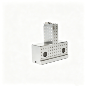
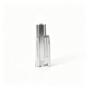
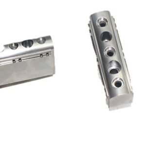
Representative Industrial Equipment Components


Related Configurable Component Families and Quotation





Why Engineering Teams Choose SUUXIANG for Industrial Equipment Components
Drawing-driven coordination for custom parts where process decisions, inspection priorities, and revision control must remain clear.
Drawing-Led DFM Review
We review critical dimensions, datums, machining access, and tolerance risks before quotation so your industrial equipment components begin with a practical route.
Process Route Planning
CNC machining, EDM, grinding, and fitting are planned around geometry, material condition, surface requirements, and the dimensions that matter most.
EDM and Grinding Coordination
Electrode strategy, wire paths, grinding stock, and heat-treatment sequence are considered together to protect form, finish, and achievable inspection results.
Inspection Plan Alignment
Inspection methods and reporting needs are defined against critical features, helping align measurement expectations with the drawing and verified production plan.
Revision Visibility
Controlled communication keeps drawing revisions, clarified requirements, and delivery information visible, reducing avoidable uncertainty as the project moves into production.
Traceable Communication
Questions, decisions, and inspection expectations remain tied to the project record, giving engineering, quality, and sourcing teams clearer handoffs.
Precision Components and Tooling Categories
Drawing-driven manufacturing families for CNC parts, mold components, connector tooling, die components, and controlled prototype or low-volume requirements.

CNC Machining Services
Precision CNC machining services for drawing-based custom parts, using the appropriate milling, turning, EDM, grinding, fitting, and inspection route. RFQ review should identify material, critical dimensions, datums, surface requirements, quantity, and reporting needs before commitments are made.
Upload a Drawing
CNC Milling
Custom CNC milling services for prismatic, contoured, pocketed, and feature-rich components. Drawing review considers clamping strategy, tool access, datum references, internal-corner geometry, machining allowance, and the dimensions that require inspection planning.
Upload a Drawing
CNC Turning
Precision CNC turning services for shafts, sleeves, pins, bushings, threaded features, and rotational parts. Process planning addresses concentricity, runout, datum selection, workholding, cross features, material condition, and finishing or grinding requirements.
Upload a Drawing
5-Axis Machining
5-axis CNC machining for parts whose geometry benefits from multi-face access, compound angles, or reduced setups. Feasibility depends on tool reach, workholding, feature depth, tolerance relationships, material condition, and the inspection approach defined from the drawing.
Upload a Drawing
Swiss & Micro Machining
Swiss machining and micro machining for small, slender, and detail-dense turned components. A responsible review evaluates stock size, length-to-diameter ratio, feature sequence, tool access, burr control, handling risk, critical dimensions, and measurement method.
Upload a Drawing
Wire & Sinker EDM
Wire EDM and sinker EDM services for hardened materials, fine internal details, sharp geometry, deep features, and profiles that conventional cutters cannot reach efficiently. Electrode strategy, wire path, recast-layer considerations, finish requirements, and downstream fitting should be reviewed early.
Upload a Drawing
Precision Grinding
Precision surface and profile grinding for controlled flatness, parallelism, profile accuracy, and final-size finishing. Grinding plans require clear datum strategy, grinding stock, material and heat-treatment condition, surface requirements, and a practical inspection method.
Upload a Drawing
Mold Core & Mold Cavity Inserts
Precision mold core and cavity inserts manufactured from customer drawings and specifications. Review focuses on mold shutoff geometry, cooling or venting features, machining and EDM access, heat-treatment sequence, polishing requirements, mating relationships, and critical dimensions.
Upload a Drawing
Ejector & Ejection Components
Ejector pins, sleeves, and ejection components for mold systems, including drawing-based custom configurations. Requirements should define movement interfaces, clearance relationships, hardness or treatment needs, wear surfaces, tip geometry, finishing expectations, and inspection priorities.
Upload a Drawing
Core Pins, Guide & Locating Components
Core pins, guide pins, and locating components produced to the dimensions and mating requirements of the tool design. Review should establish functional datums, fit class, alignment relationships, wear considerations, material condition, and any grinding or EDM finishing needed.
Upload a Drawing
Slides, Lifters, Gates & Mold Accessories
Mold slides, lifters, gates, and accessories manufactured as configurable tooling components. Planning considers travel and interference, shutoff surfaces, wear zones, cooling or venting needs, machining access, fitting requirements, heat treatment, and inspection of functional interfaces.
Upload a Drawing
Connector Mold Components
Precision connector mold components for applications with dense cavities, fine features, tight alignment relationships, and repeatable mating conditions. Drawing review addresses insert geometry, pin or terminal-related features, EDM needs, material treatment, surface condition, and inspection criteria.
Upload a Drawing
Stamping Die Components
Precision stamping die components for drawing-based die assemblies, including wear-critical and alignment-critical parts. Process planning considers material, heat treatment, cutting or forming geometry, clearance relationships, grinding stock, EDM strategy, surface condition, and fitting requirements.
Upload a Drawing
Injection Mold Components, MIM, CIM & Overmolding Tooling
Tooling and component work associated with injection molding, metal injection molding, ceramic injection molding, and overmolding when within verified production scope. Review begins with the drawing, material requirements, molding context, critical interfaces, process route, and inspection expectations.
Upload a Drawing
Machining Materials
CNC machining materials selected against the drawing, application, required properties, heat-treatment condition, and machining route. Confirm the specified grade, material form, traceability needs, corrosion or wear environment, and any substitute-material approval before production.
Upload a Drawing
Surface Finishes & Heat Treatment
Surface finishing and heat treatment planned around functional surfaces, dimensional change, wear, corrosion, appearance, and downstream assembly. Specifications should identify the required treatment or finish, masking or selective areas, sequencing, thickness limits, and relevant inspection criteria.
Upload a Drawing
Quality, Metrology & Documentation
Precision inspection, metrology, and quality documentation aligned to the order and verified inspection plan. Customers should identify critical dimensions, datums, measurement method expectations, reporting format, traceability requirements, revision level, and any first-article or final-inspection needs.
Upload a Drawing
Prototyping & Low-Volume Production
Rapid prototyping and low-volume manufacturing for drawing-based parts and tooling components where design learning, validation, or controlled initial demand matters. Provide revision status, quantity, material, critical dimensions, surface requirements, delivery target, and required inspection evidence.
Upload a DrawingMaterials for Industrial Equipment Components

Alloy Tool Steel
A robust choice for mold inserts, core pins, and wear-critical tooling where hardness and dimensional stability matter. Heat-treatment sequence, grinding stock, and EDM strategy should be defined against the drawing.

Stainless Steel
Used for corrosion-sensitive industrial equipment components, connector tooling, and precision assemblies. Grade selection affects machinability, corrosion behavior, and attainable surface condition, so confirm the specified alloy and any required heat treatment.

Carbon Steel
A practical material for structural machine parts, locating features, and die components when controlled strength and cost are important. Specify the grade, coating needs, and heat-treatment condition to align machining and inspection planning.

Aluminum Alloys
A lightweight option for fixtures, housings, prototypes, and non-wear components requiring efficient CNC machining. Alloy and temper influence stiffness, corrosion response, and finish quality; confirm mating interfaces and surface-treatment requirements early.

Copper Alloys
Applicable to selected conductive, thermal-management, and electrode-related industrial equipment components. Copper-alloy grade affects electrical performance, machinability, and tool wear, requiring confirmation of functional requirements, geometry, and inspection priorities before routing.
Industrial Equipment Components: Supported Machining and Finishing

CNC Milling
CNC milling forms prismatic features, pockets, bores, and mounting faces from drawing-controlled stock. Tool access, clamping strategy, and datum locations are reviewed to support functional geometry and consistent downstream inspection.

CNC Turning
CNC turning produces rotational industrial equipment components such as shafts, sleeves, bushings, and threaded features. Concentricity requirements, workholding, material condition, and critical diameter measurements guide the proposed machining route.


Wire and Sinker EDM
Wire EDM and sinker EDM address precise contours, narrow slots, internal corners, and hardened-material features where conventional tool access is limited. Electrode strategy, wire path, recast-layer considerations, and finishing requirements require project review.

Precision Grinding
Precision grinding refines critical flatness, parallelism, diameter, and surface requirements after suitable machining or heat-treatment stages. Grinding stock, datum control, and measurement method are planned around the drawing and functional mating conditions.

Fitting and Inspection
Fitting and inspection verify assembly-relevant relationships, critical dimensions, and specified documentation against the agreed plan. Results, revision status, and delivery details are coordinated to match the order’s verified quality requirements.
Industrial Equipment Components: Verified Add-On Requirements

Heat Treatment
Hardening, tempering, nitriding, or other specified heat-treatment requirements are reviewed with material, sequence, grinding allowance, and critical dimensions before the production route is confirmed.

Surface Finishing
Surface treatments, coatings, polishing, or texture requirements are planned around functional surfaces, corrosion expectations, mating conditions, and dimensional effects that may require allowance or post-process verification.

Part Marking
Part numbers, revision identifiers, batch references, or customer-specified markings can be considered where location, method, legibility, and any impact on critical surfaces are defined in the drawing.

Assembly Fitting
Fitting support can be planned for components with defined mating relationships, such as slides, inserts, guide elements, or connector tooling details, when assembly context and acceptance criteria are supplied.

Inspection Documentation
Inspection reports and supporting documentation are prepared to the agreed inspection plan, with critical dimensions, datums, reporting format, traceability needs, and revision status aligned to the order.
Industrial Equipment Components, Built from Drawings
SUUXIANG is the sole public-facing brand of Dongguan SuuXiang Precision Mold Co., Ltd., established in 2010 and based on the 2nd Floor of Sanhe Industrial Park, Chang’an Town, Dongguan, Guangdong, China. Founded by XiaoCheng Huang, the company helps international engineering and sourcing teams convert drawings and specifications into inspected industrial equipment components, precision mold parts, connector tooling, and custom machined work.
Our manufacturing workflow combines CNC milling and turning, multi-axis machining, EDM, precision grinding, fitting, and inspection. Before quotation or production commitments, we review critical dimensions, datums, machining access, material and heat-treatment requirements, surface priorities, and inspection expectations to define a practical process route.
What differentiates SUUXIANG is disciplined drawing review and visible project control. We focus on DFM, revision traceability, critical-to-quality features, and order-specific documentation so buyers can assess manufacturability and quality evidence before production begins. Submit your drawing, quantity, delivery target, and reporting requirements for a focused manufacturing discussion.

Core Capabilities for Industrial Equipment Components
Drawing Review Before Commitment
SUUXIANG reviews drawings and models before quoting industrial equipment components, focusing on critical dimensions, datums, material requirements, machining access, surface requirements, and quantity. This early DFM discussion identifies production questions while design changes remain manageable.
- Confirm critical-to-quality dimensions and datum references
- Review tolerance stack, tool access, and feature geometry
- Clarify material, heat treatment, and surface requirements
- Align quantity, delivery targets, and inspection needs

CNC and EDM Process Planning
Complex geometry often requires more than a single machining operation. SUUXIANG plans the appropriate CNC milling, turning, multi-axis machining, wire EDM, or sinker EDM sequence around part geometry, access constraints, material condition, and the dimensions that control function.
- Select CNC routes for accessible profiles and features
- Assess wire paths for narrow slots and internal contours
- Plan electrodes for enclosed or detailed EDM features
- Sequence operations around heat treatment and distortion risk

Grinding and Fitting Strategy
For industrial equipment components with functional interfaces, grinding stock and fitting requirements must be established before final operations. SUUXIANG evaluates surfaces, mating relationships, and finishing sequence so that precision work supports assembly intent rather than creating avoidable rework.
- Define grinding allowance before semi-finish machining
- Identify surfaces requiring controlled flatness or parallelism
- Review fits against mating parts and assembly references
- Coordinate finishing steps with inspection checkpoints

Inspection and Revision Control
Production is supported by an inspection plan tied to the approved drawing revision and project requirements. SUUXIANG keeps material, dimensional priorities, reporting expectations, and delivery information visible through coordination, helping buyers receive documentation aligned with the verified order scope.
- Match inspection methods to critical dimensions and datums
- Maintain approved drawing and revision visibility
- Confirm reporting requirements before production begins
- Coordinate final documentation with the inspection plan

Why Choose SUUXIANG for Industrial Equipment Components
Compare a drawing-led manufacturing workflow with generic quote-only sourcing before committing critical parts to production.
← Swipe left or right to view →
Industrial Equipment Components: Drawing to Inspected Parts
A drawing-led workflow that aligns DFM, process planning, inspection, and delivery coordination before production commitments are made.
RFQ and Drawing Intake
Send 2D drawings, available 3D models, material, quantity, application context, delivery target, and inspection requirements so the team can identify missing information before quotation.
DFM and Critical Review
SUUXIANG reviews critical dimensions, datums, tolerance stacks, tool access, surfaces, heat-treatment sequence, and likely EDM or grinding needs, then clarifies manufacturability and revision status.
Process Route Planning
After requirements are aligned, the project route defines machining operations, fixtures, electrode strategy, wire paths, grinding stock, inspection methods, and controlled communication milestones.
Machining, EDM, and Grinding
Parts progress through the approved CNC, EDM, grinding, and fitting sequence. Process decisions remain tied to drawing revisions, critical features, and the agreed manufacturing plan.
Inspect, Pack, and Coordinate
Inspection follows the order-specific plan and final documentation is matched to verified results. Parts are protected for shipment, while delivery details and traceability remain visible.
Industrial Equipment Components: How to Work With SUUXIANG
Move from drawing review to inspected delivery through a defined, drawing-led workflow.
Submit Your Requirements
Send the 2D drawing, available 3D model, material, quantity, quality expectations, target delivery date, and application context for your industrial equipment components.
Review DFM and Quotation
Align on critical dimensions, datums, machining access, EDM or grinding needs, inspection requirements, revision status, process route, and quotation assumptions before production commitments.
Approve First Articles
When applicable, review samples or first articles against the agreed drawing and inspection plan, then resolve findings before progressing to the approved production stage.
Coordinate Production and Delivery
SUUXIANG coordinates machining, EDM, grinding, fitting, inspection, revision visibility, and delivery information according to the confirmed order requirements and verified documentation plan.
Industrial Equipment Components: Verified Customer Feedback
This space is reserved for a verified customer testimonial. SUUXIANG will publish project context, approved customer attribution, and substantiated outcomes only after the customer has authorized the information for public use.
This space is reserved for a verified customer testimonial. Any published case summary will identify the relevant drawing-review, manufacturing, inspection, or delivery outcome without disclosing confidential design or sourcing information.
This space is reserved for a verified customer testimonial. SUUXIANG will add ratings, names, roles, company details, and measurable project results only when supported by current customer approval and project records.
Industrial Equipment Components FAQ
Practical answers for drawing-based sourcing, inspection planning, and controlled production decisions.
What is the MOQ for custom industrial equipment components?
What files are needed to quote industrial equipment components?
Can SUUXIANG provide samples before production of industrial equipment components?
How should I plan lead time for custom machined parts?
What inspection reports can be requested with an order?
How are drawing revisions controlled during production?
How are payment and shipping arranged for international orders?
How does SUUXIANG handle IP and confidential drawings?
Submit Your Drawing for DFM Review
Use this decision framework to define requirements, evaluate drawing-based suppliers, control quality and cost, and avoid sourcing mistakes in precision CNC, mold, connector-tooling, and stamping-die component programs.
1. What Are industrial equipment components?
Two sourcing categories sit behind industrial equipment components: catalog replacement parts and drawing-based, application-specific parts. Catalog items are selected by a published part number, while custom components are manufactured to controlled dimensions, material, interfaces and inspection requirements.
Four production contexts commonly require the latter: machinery mechanisms, precision molds, connector tooling and stamping dies. A core pin, locating component, slide, die insert or custom machined part may determine alignment, motion, forming accuracy, wear behavior or mating performance within a larger assembly.
Six RFQ inputs establish a usable starting point: 2D drawing, 3D model when available, material and heat-treatment requirements, quantity, critical dimensions and surface requirements. Buyers should also state datums, mating context, inspection or reporting needs, revision level and target delivery date so the proposed CNC, EDM, grinding and fitting route can be reviewed against the actual application.
2. How industrial equipment components evolved
By the late 19th century, standardized threads, bearings, shafts, and fasteners made replacement parts more interchangeable and simplified machine assembly. Components were specified mainly by nominal dimensions and fit classes, but application-specific interfaces still required careful drawing control.
In the 1940s, numerical-control development began shifting repeatable complex geometry from manual machine setup toward programmed motion; later CNC expanded that approach across turning, milling, and grinding. Precision machining made datum selection, tolerance stacks, machining allowance, and inspection planning central to component design.
Since the 1990s, CAD models, modular automation, and digital document exchange have shortened prototype-feedback loops and connected suppliers across borders. Current industrial equipment components programs therefore expect controlled revisions, traceable material and inspection records, rapid DFM feedback, and explicit coordination of critical dimensions before production.
3. Types of industrial equipment components
Industrial equipment components should be classified by function, drawing risk, and process route. That framing makes RFQs comparable before SUUXIANG reviews manufacturability.
CNC-Machined Parts
One shaft, housing, or locator may transmit, seal, or position; drawings define datums, fits, threads, and surfaces.
Two questions: which dimensions need milling, turning, grinding, or EDM, and what inspection proves them?
Precision Mold Components

One core insert forms part geometry; drawings specify shutoffs, cooling interfaces, hardness, and finish.
Two checks: where are wire or sinker EDM needed, and which fitting datum controls assembly?
Connector Tooling Parts

One connector insert produces terminal or housing features; drawings define pitch, cavities, and mating datums.
Two decisions: micro-machining or EDM, and how will pitch be inspected?
Stamping-Die Components
One die component guides, cuts, or forms strip; drawings define clearance, radii, alignment, and wear faces.
Two questions: what heat-treatment sequence applies, and what grinding stock remains?
Fabricated Or Stamped Parts
One bracket or stamped blank provides support; drawings define bend radii, flat patterns, holes, and weld zones.
Two questions: what formed-geometry tolerance applies, and is secondary machining required?
Prototypes And Low-Volume Builds
One low-volume build validates interfaces; drawings identify revision, critical dimensions, material, and quantity.
Two questions: what is the shortest qualified route, and which reports accompany first articles?
4. Materials for industrial equipment components
Material selection starts with the load path, environment, temperature, electrical function, tolerance stability, machining route, and total part cost. A drawing should identify the material standard, required condition, and any heat treatment before quotation.
| Material Family | Advantage | Limitation | Typical Use | Request |
|---|---|---|---|---|
| Carbon or alloy steel | Strength and machinability | Needs corrosion protection | Shafts, fixtures, brackets | Mill certificate, heat treatment |
| Stainless steel | Corrosion resistance | Higher machining cost | Washdown parts, housings | Material certificate, passivation |
| Aluminum alloy | Low mass | Lower wear resistance | Covers, moving structures | Material certificate, finish |
| Copper alloy | Conductivity | Soft, costly | Contacts, thermal features | Alloy certificate, plating |
| Tool steel | Wear resistance | Heat-treatment distortion | Mold and die components | Hardness record, inspection |
| Engineering plastic | Low friction | Creep and temperature limits | Guides, isolators | Grade certificate, application limits |
Match Material To Service
Steel grades suit loaded shafts, brackets, and wear interfaces; stainless grades fit corrosive or washdown exposure. Aluminum reduces moving mass, while copper alloys serve conductive contacts or heat-transfer features.
Control Stability And Cost
Tool steels are appropriate for high-wear tooling features, but their heat-treatment sequence and grinding stock affect final dimensions. Engineering plastics can reduce friction or weight, yet creep, moisture response, and temperature limits require application review.
Request Traceable Evidence
Each RFQ should state the material designation, condition, hardness range where applicable, and corrosion or electrical requirement. Request mill certificates, heat-treatment records, coating evidence, and inspection results tied to the drawing revision.
5. Customizing industrial equipment components
Drawing-based customization begins by separating performance requirements from appearance preferences. SUUXIANG reviews geometry, datums, mating conditions, material, quantity, and inspection needs before confirming a manufacturable process route.
| Customization Type | Specify On Drawing | Priority |
|---|---|---|
| Functional | Fits, threads, finish, heat treatment | Critical |
| Identification | Part number, revision, marking | Traceability |
| Delivery | Packaging, rust protection, report format | Project-specific |
Define Functional Requirements
One controlled drawing should identify critical dimensions, fits, threads, surface finish, heat treatment, and coating requirements.
Two categories prevent unnecessary cost: functional requirements affect assembly or life; cosmetic requirements may be negotiable.
- Critical-to-quality dimensions and datums
- Thread class, engagement, and gauge method
- Mating-part context and load direction
Review DFM Before Release
A DFM review checks tool access, corner radii, wall geometry, EDM needs, grinding stock, and heat-treatment sequence.
Each tolerance should be tied to function; tighter limits without a measurement plan create quoting and acceptance risk.
Control Identification And Delivery
Revision identifiers, part markings, protective packaging, and inspection reports support traceability but do not replace functional specifications.
One released revision, approval record, and deviation process keep production aligned when drawings or cosmetic details change.
6. Quality elements that affect performance
A 2D drawing should define the assembly-critical datums before individual dimensions are tightened. For industrial equipment components, performance depends on how geometry, material condition, finish, and inspection evidence connect to the mating part.
Datums And Functional Tolerances
Three datum features can establish a repeatable inspection frame: a mounting face, locating bore, and clocking feature. Apply GD&T only to functional relationships, specifying position, perpendicularity, runout, or profile where assembly requires them.
A first article should report critical dimensions against the stated datums, not against convenient machine setups. Define acceptance limits, measurement method, and revision level on the drawing or inspection plan.
Material And Surface Condition
Material verification should match the ordered grade, condition, and any required traceable record. Heat treatment requires a specified sequence because machining, EDM, and grinding allowances can change after thermal processing.
Surface requirements should distinguish roughness from cosmetic appearance. Call out deburring limits, prohibited sharp edges, cleaning requirements, and protected sealing or sliding surfaces.
Fits, Concentricity, And Records
Concentric bores, shafts, and bearing seats need a datum-based runout or position requirement rather than an implied expectation. State the mating condition, fit class or limit dimensions, and whether inspection occurs before or after coating.
An inspection plan should identify 100% checks, sampled features, gauges, and report format. SUUXIANG can review these requirements from the drawing, model, application context, and agreed acceptance criteria before production.
7. Choosing an industrial equipment components manufacturer
A supplier decision should begin with the released drawing, 3D model, application context, and critical dimensions. For industrial equipment components, compare evidence for the actual process route—not broad catalog language.
| Evaluation Area | Evidence To Request | Decision Signal |
|---|---|---|
| DFM | Marked-up drawing review | Risks identified early |
| Quality | Inspection example and material record | Requirements are traceable |
| Scale-Up | Prototype and production plan | Route can change responsibly |
| Revisions | Change-control example | Latest revision remains visible |
Engineering Communication And DFM
A 2D drawing review should identify datums, tolerance stacks, tool access, heat-treatment sequence, EDM needs, and grinding stock before quotation.
- Request marked-up DFM feedback
- Confirm revision-control method
- Provide mating-part constraints
Process And Quality Evidence
A process review should match CNC, EDM, grinding, fitting, and inspection to the part’s features. Ask for project-relevant capability details, sample inspection reports, material records, and comparable references.
Samples, Delivery, And Revisions
A first article should use an agreed inspection plan and documented acceptance criteria. Confirm prototype-to-production planning, lead-time assumptions, change handling, and delivery-status communication.
8. Common industrial equipment components sourcing mistakes
Most sourcing failures begin before a machine starts: the RFQ leaves critical decisions implicit. For industrial equipment components, make manufacturing evidence and revision ownership explicit before release.
Incomplete Drawing Packages
Each RFQ needs a controlled 2D drawing, current 3D model, datums, and CTQ callouts. Missing interfaces force assumptions that can make otherwise accurate parts unusable.
- Attach mating-part geometry or interface dimensions
- Identify functional datums and critical features
Ambiguous Tolerances And Materials
Every nonstandard tolerance, material grade, hardness condition, finish, and masking area needs a drawing note or specification reference. General notes cannot reliably convey where grinding, EDM, or post-treatment stock is required.
- State tolerance units and applicable standard
- Specify finish roughness and inspection location
Piece Price Without DFM
Lowest quoted unit price can omit the process controls needed for a stable result. Request a DFM review covering tool access, machining sequence, electrode strategy, heat-treatment distortion, and realistic inspection methods.
- Compare quotations against the same revision
- Resolve manufacturability exceptions before purchase order
Undefined Inspection And Revisions
A part can pass a supplier’s assumed checks yet fail assembly when acceptance criteria and mating interfaces are unstated. Define measurement methods, report requirements, assembly-critical dimensions, and one revision-controlled approval path.
- Name the approved drawing revision
- Require documented change acknowledgement
- Confirm gauge, datum, and sampling expectations
9. Launching a custom component program
1 launch owner should consolidate the controlled 2D drawing, 3D model, revision level, material, quantity, application and inspection needs before requesting quotations. A gated workflow prevents an industrial equipment components program from moving forward on assumptions.
Capture Requirements
Gate 1 belongs to the buyer and design owner. Exchange CTQ dimensions, datums, surface requirements, mating context, heat-treatment sequence, target date and required records.
Review DFM And Quotes
Gate 2 requires supplier feedback before award. SUUXIANG should identify tool access, EDM or grinding needs, tolerancing risks, inspection approach, assumptions, lead-time basis and revision conflicts; procurement compares like-for-like scopes.
Approve Prototype Evidence
Gate 3 is first-article approval by engineering and quality. The supplier submits parts and agreed measurement evidence; deviations need written disposition before a pilot build or low-volume release.
Release And Control Changes
Gate 4 releases repeat production only after pilot acceptance. Program management maintains the approved revision, inspection plan, packaging and delivery instructions; every drawing or process change requires documented impact review and authorization.
10. Industrial equipment components pricing and cost
1 drawing can produce different total costs when material grade, heat treatment, machining access, tolerance, surface finish, inspection, packaging, and freight change. For industrial equipment components, compare the complete landed requirement, not a unit-price line alone.
2 process decisions usually dominate before volume does: multi-axis machining, EDM, grinding, special workholding, and first-article reporting add setup and verification effort. Release stable revision-controlled data and identify only truly critical dimensions before requesting a comparable quotation.
| Quantity tier | Cost behavior | Setup allocation | Lead-time consideration | Buyer action |
|---|---|---|---|---|
| 1–5 pieces | Highest unit cost; engineering and setup dominate | Allocated across few parts | Allow drawing review, programming, material preparation, and inspection planning | Simplify noncritical features; supply 2D and 3D files |
| 6–50 pieces | Setup is shared; process repetition improves efficiency | Moderate per-part allocation | Batch machining and outside processes may set schedule | Use common material, finish, and inspection requirements |
| 51–250 pieces | Unit cost can fall when fixturing and tool paths are reused | Low per-part allocation | Confirm capacity, batch size, packaging, and freight plan | Freeze revisions; consolidate releases and delivery dates |
| 250+ pieces | Economics require a project-specific route review | Evaluate dedicated tooling or fixtures | Validate capacity, quality plan, and logistics before commitment | Request a total-cost comparison including inspection, packaging, and freight |
Upload Industrial Equipment Components Drawings for DFM Review
Send 2D and 3D files with material, quantity, quality, inspection, application, and delivery requirements for a disciplined manufacturing review.