
PCB and EMS Tooling Components From Your Drawings
SUUXIANG reviews critical dimensions and plans CNC, EDM, and grinding routes before producing inspected PCB and EMS tooling components with revision control.
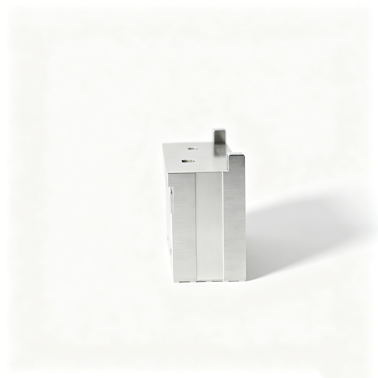
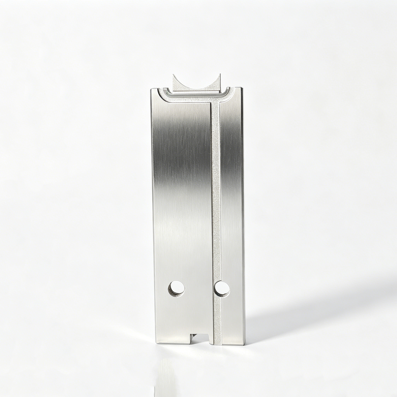
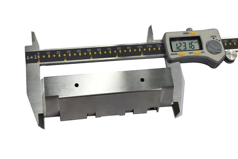
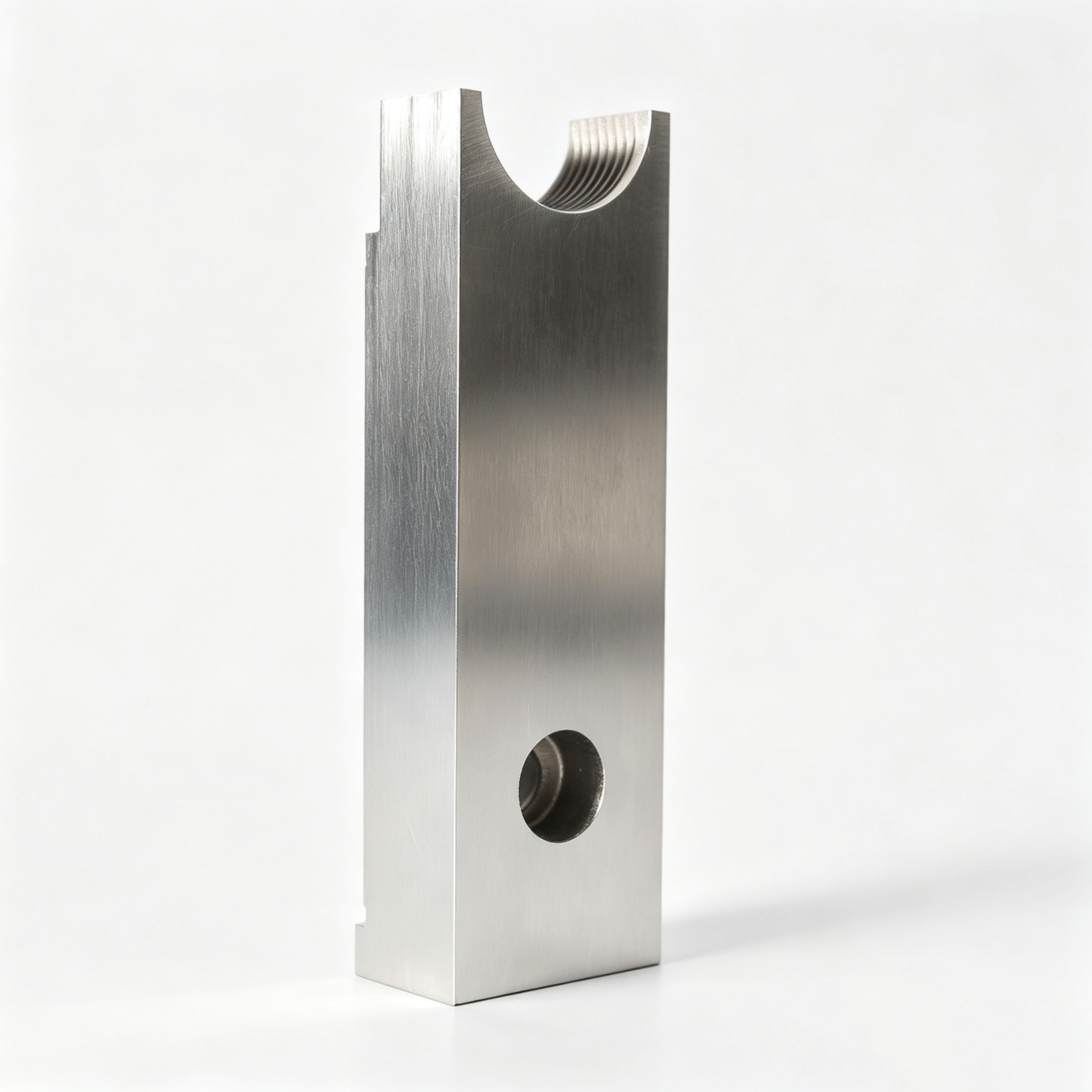
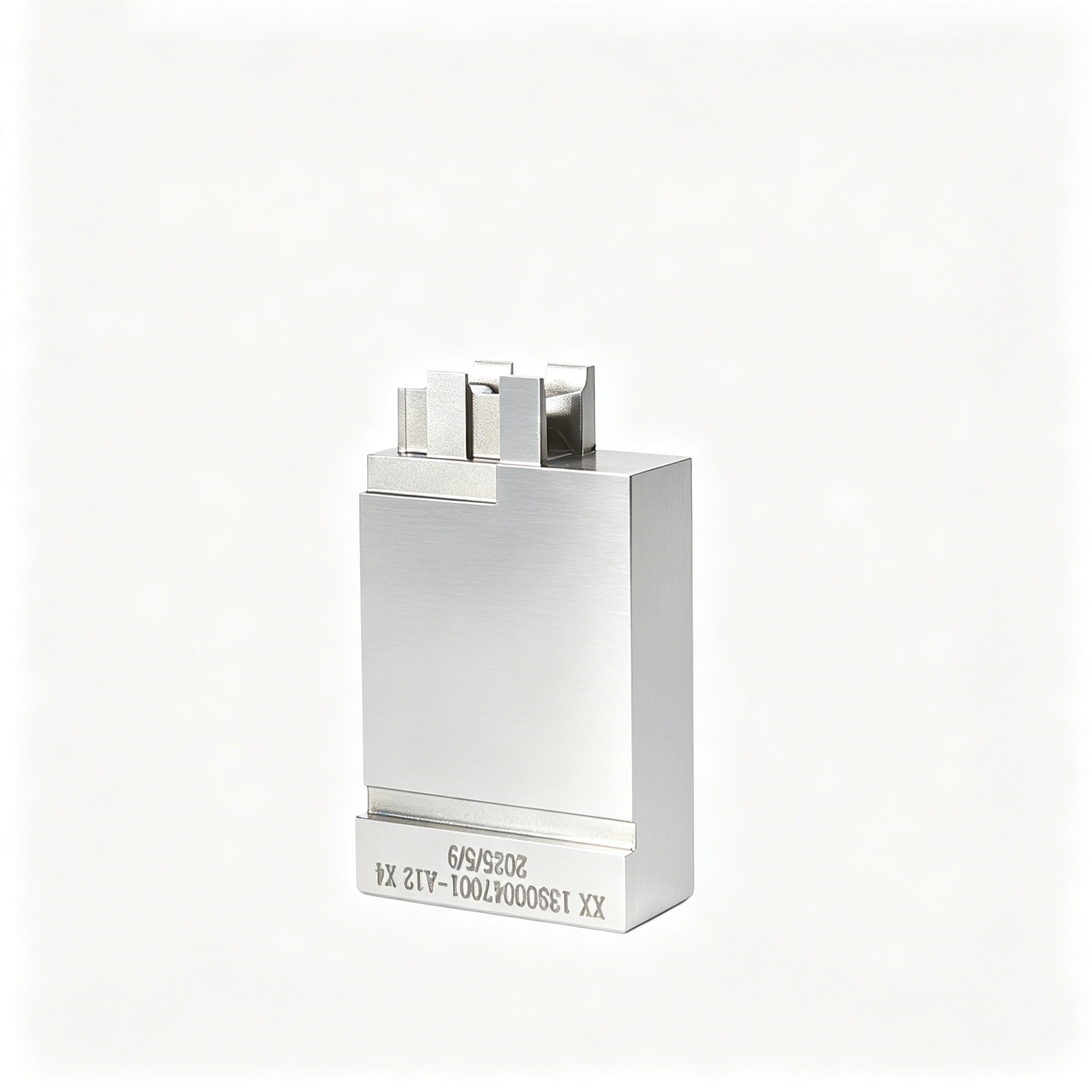
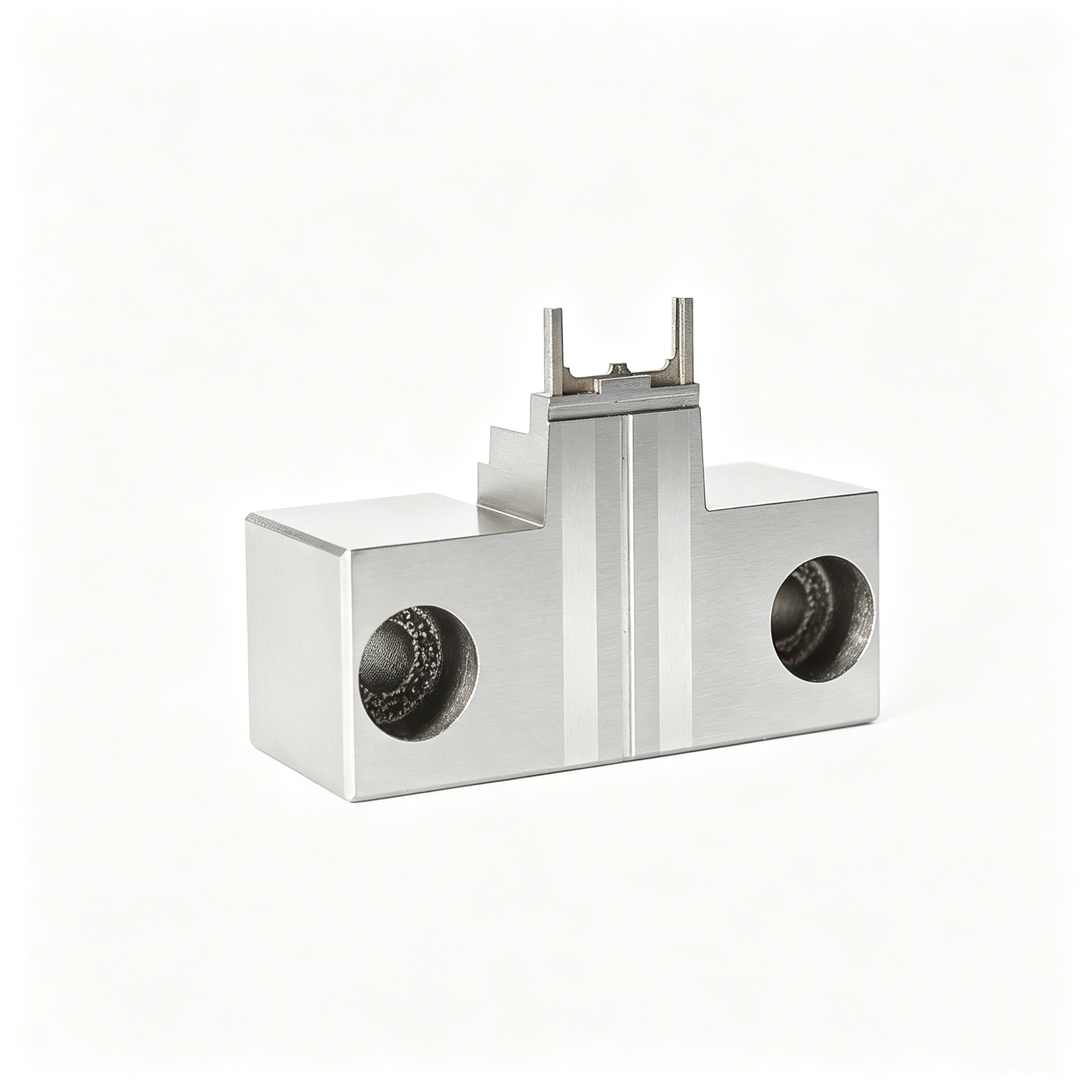
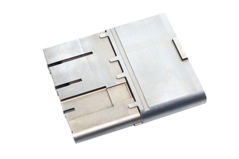
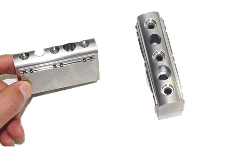
Representative PCB and EMS Tooling Components





Related Configurable Components and RFQ Options


PCB and EMS Tooling Components: Controls Before Metal Is Cut
A drawing-led workflow that aligns manufacturability, critical dimensions, process decisions, and inspection expectations before production begins.
DFM Before Quotation
Review drawing completeness, tool access, datums, materials, and critical features before committing to a machining route or quotation.
Critical-Dimension Planning
Identify CTQ dimensions and tolerance relationships early, then match machining, EDM, grinding, and inspection methods to the requirement.
Process-Route Decisions
Plan the practical sequence for CNC machining, heat treatment, EDM, grinding, fitting, and allowance control around part geometry.
Revision Control
Keep drawing revisions, clarified requirements, and production-facing decisions visible so teams can verify the correct manufacturing basis.
Inspection Planning
Define measurement priorities, datum references, reporting expectations, and inspection methods that correspond with the agreed drawing and order.
Traceable Communication
Maintain clear project communication on technical questions, change status, quality expectations, and delivery coordination throughout the manufacturing workflow.
PCB & EMS Tooling by Manufacturing Family
Drawing-driven process routes for configurable precision components, with DFM, critical-dimension review, inspection planning, and revision control aligned before production.

CNC Machining Services
Precision CNC machining services for drawing-based custom parts, mold details, and tooling components. Process planning considers datums, critical dimensions, material condition, machining access, and inspection requirements before a production route is confirmed.
Upload a Drawing
CNC Milling Services
Custom CNC milling services for prismatic parts, plates, inserts, pockets, and complex machined features. Drawing review addresses fixture strategy, tool reach, corner radii, wall geometry, machining allowance, and dimensional priorities.
Upload a Drawing
CNC Turning Services
Precision CNC turning services for shafts, pins, sleeves, bushings, and rotational features. Requirements are reviewed for concentricity, runout, threads, surface finish, datum relationships, material condition, and any downstream grinding or EDM needs.
Upload a Drawing
5-Axis Machining
5-axis CNC machining supports multi-face geometry and features that benefit from fewer setups. SUUXIANG evaluates tool access, fixture constraints, feature orientation, tolerance relationships, and inspection approach against the supplied drawing and model.
Upload a Drawing
Swiss & Micro Machining
Swiss machining and micro machining support small-diameter, slender, and detail-intensive components where handling and feature control matter. Review focuses on geometry, material, tolerance stack, burr control, surface requirements, and feasible inspection methods.
Upload a Drawing
Wire & Sinker EDM
Wire EDM and sinker EDM services support hardened materials, narrow slots, sharp internal geometry, and features inaccessible to conventional cutting tools. Electrode strategy, wire path, corner requirements, recast-layer considerations, and finishing allowances are reviewed first.
Upload a Drawing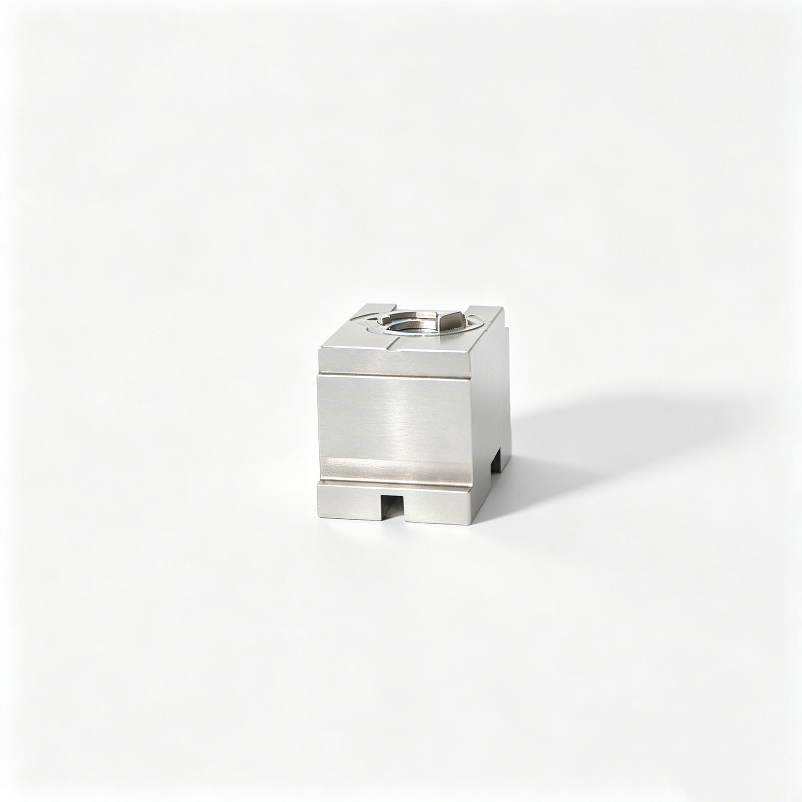
Precision Grinding
Precision surface and profile grinding is applied where flatness, parallelism, profile control, and final-size requirements require a controlled finishing route. Grinding stock, heat-treatment sequence, datum control, and inspection method should be established before release.
Upload a Drawing
Mold Core & Cavity Inserts
Precision mold core and cavity inserts are produced from customer drawings for tooling applications requiring controlled geometry, mating relationships, and surface requirements. CNC, EDM, grinding, fitting, and inspection are selected according to the verified component requirements.
Upload a Drawing
Ejector & Ejection Components
Ejector pins, sleeves, and ejection components are evaluated around fit, travel, wear conditions, hardness requirements, and mating-part relationships. Buyers should provide drawing details, material and heat-treatment requirements, critical dimensions, and applicable inspection expectations.
Upload a Drawing
Core Pins, Guide & Locating Components
Core pins, guide pins, and locating components require attention to datum strategy, concentricity, fit class, wear surfaces, and mating geometry. Manufacturing routes may combine turning, milling, grinding, EDM, and inspection based on the drawing.
Upload a Drawing
Slides, Lifters, Gates & Mold Accessories
Mold slides, lifters, gates, and accessories are configurable tooling components made to drawing-defined geometry and functional interfaces. DFM review considers travel or mating conditions, tool access, wear areas, heat treatment, surface needs, and fitting requirements.
Upload a Drawing
Connector Mold Components
Precision connector mold components support connector-product tooling where fine features, alignment, repeated mating conditions, and dimensional consistency are significant. SUUXIANG reviews critical geometry, material, EDM or grinding needs, inspection points, and revision status before manufacture.
Upload a Drawing
Stamping Die Components
Precision stamping die components are produced for drawing-defined die assemblies, including inserts, punches, plates, guides, and locating details. Process planning accounts for material condition, heat treatment, grinding stock, EDM geometry, fit, and inspection requirements.
Upload a Drawing
Injection, MIM, CIM & Overmolding Tooling
Injection, MIM, CIM, and overmolding tooling components are supported when requirements fall within verified production scope. Submit the drawing, application context, material, critical dimensions, surface requirements, quantity, and quality expectations for technical review.
Upload a Drawing
Machining Materials
CNC machining materials are selected from the drawing and application requirements, including machinability, strength, hardness, corrosion resistance, stability, and downstream finishing needs. Material grade, condition, traceability expectations, and substitutions should be defined before quotation.
Upload a Drawing
Surface Finishes & Heat Treatment
Surface finishing and heat treatment are planned as part of the dimensional process route, not added after machining. Specify finish, hardness, coating, masking, cosmetic priorities, and critical dimensions so allowances and inspection requirements can be evaluated.
Upload a Drawing
Quality, Metrology & Documentation
Precision inspection, metrology, and quality documentation are aligned to drawing-defined critical dimensions and the agreed inspection plan. Customers should identify report requirements, datums, sampling expectations, material records, revision status, and acceptance criteria with the RFQ.
Upload a Drawing
Prototyping & Low-Volume Production
Rapid prototyping and low-volume manufacturing support validation builds, tooling trials, engineering revisions, and controlled early production. A useful RFQ includes drawings, model files, material, quantity, quality priorities, target delivery date, and revision-controlled specifications.
Upload a DrawingMaterial Requirements for PCB and EMS Tooling Components

Tool Steels
Commonly specified for durable mold inserts, punches, and forming features. Grade, supplied condition, hardness target, and heat-treatment sequence are reviewed with machining allowance, EDM strategy, grinding stock, and critical-dimension requirements.

Stainless Steels
Often selected where corrosion resistance, cleanliness, or long-term environmental exposure matters. Material grade, hardness condition, surface requirement, and mating function should be evaluated alongside tool access, finishing method, and inspection criteria.

Copper Alloys
Used for inserts or tooling features where thermal behavior is important. Alloy selection, electrical or thermal requirements, deformation risk, and surface finish need drawing-level review before CNC machining, EDM, fitting, and dimensional inspection are planned.

Aluminum Alloys
Suitable for selected prototype fixtures, structural tooling, and low-load production aids. Alloy grade, temper, rigidity, wear expectations, and surface treatment must be matched to the application before production acceptance and inspection planning.

Cemented Carbide
Specified for high-wear pins, punches, and precision forming details. Grade, geometry, machining access, EDM or grinding approach, edge condition, and measurement method require early review because material behavior affects the feasible process route.
PCB and EMS Tooling Components: CNC, EDM, Grinding and Fitting


Wire EDM
Wire EDM produces precise through profiles, narrow slots and intricate contours where conventional cutter access is limited. The wire path, start-hole location and required edge condition should be reviewed against critical dimensions.

Sinker EDM
Sinker EDM forms deep cavities, sharp internal details and complex blind features using a planned electrode strategy. Electrode wear, finish expectations and subsequent fitting or polishing requirements are considered during process planning.

Precision Grinding
Precision grinding controls flatness, parallelism, diameter and finished surfaces after machining or heat treatment. Grinding stock, datum references and inspection method must be defined so the final dimension is evaluated consistently.

Fitting Inspection
Fitting verifies functional relationships between mating tooling parts, while inspection checks agreed critical dimensions against the order plan. Revision control, measurement requirements and documentation expectations remain visible through final delivery.
PCB and EMS Tooling Components: Functional Features

Locating Features
Dowel bores, locating pins, keyways and datum surfaces establish repeatable positioning between tool sections, fixtures or mating parts. Define datum relationships, fit expectations and inspection points on the drawing.

Guide Components
Guide pins, bushes, wear plates and alignment faces help control relative motion in tooling. Material, hardness, lubrication conditions and replaceable interfaces should be specified where the application requires them.

Ejection Interfaces
Ejector-pin holes, return-pin seats, blade clearances and relief features support controlled ejection mechanisms. Identify critical alignment, surface requirements and any fitted relationships to guide machining, EDM and grinding planning.

Gate Features
Gate inserts, sprue details, runners and related shutoff surfaces must reflect the molding concept and material flow requirements. Provide sectional views, surface priorities and revision-controlled mating geometry for review.

Mating Interfaces
Connector nests, cavity interfaces, contact-support features and assembly datums require coordinated tolerances across mating parts. Share the relevant models and functional stack information so critical dimensions can be assessed together.
PCB and EMS Tooling Components at SUUXIANG
SUUXIANG is the public-facing brand of Dongguan SuuXiang Precision Mold Co., Ltd., established in 2010 in Chang’an Town, Dongguan, Guangdong, China. We help global engineering, sourcing, and quality teams turn drawings and specifications into inspected precision parts, mold components, connector tooling, and PCB and EMS tooling components.
Our work is drawing-driven. Before quotation or production commitments, we review critical dimensions, datums, material and heat-treatment requirements, machining access, EDM needs, grinding allowance, surface priorities, and inspection expectations. Process planning may combine CNC milling and turning, multi-axis machining, EDM, precision grinding, fitting, and inspection according to the verified project requirement.
What differentiates SUUXIANG is controlled technical communication from revision review through delivery coordination. We do not treat tooling components as an unlimited catalog: each requirement is assessed against its drawing, application, quality plan, and production route. Customers receive a practical manufacturing discussion focused on traceability, inspection evidence, and actionable DFM decisions.

From DFM Review to Inspection
Drawing Review Before Quotation
SUUXIANG reviews the drawing package, 3D model when available, material, quantity and application context before defining a workable route. The discussion identifies critical dimensions, datums, surface requirements and access constraints so pcb and ems tooling components are evaluated against the actual production requirement.
- Confirm revision level and required deliverables
- Identify critical-to-quality dimensions and datum relationships
- Review material, heat treatment and surface requirements
- Flag machining-access or assembly-context questions

CNC and EDM Strategy
Process planning considers the geometry rather than assigning a generic method. CNC machining establishes accessible features and reference surfaces, while wire EDM or sinker EDM may be considered for narrow profiles, internal detail or difficult tool access, subject to drawing review and project evidence.
- Plan feature sequence around stable datums
- Assess cutter access and remaining machining allowance
- Consider electrode strategy for non-machinable geometry
- Define wire paths where profile requirements warrant EDM

Grinding and Fitting Control
Where a component requires controlled mating, sliding or sealing relationships, grinding stock and fitting sequence should be defined before production. SUUXIANG coordinates these steps with the drawing intent, helping prevent a finished feature from being compromised by an unplanned downstream operation.
- Reserve stock for applicable grinding operations
- Review mating faces, guidance features and fit relationships
- Sequence heat treatment and finish operations deliberately
- Keep assembly-critical revisions visible during coordination

Inspection Matched to Requirements
Inspection planning should follow the order’s critical features and agreed reporting needs. SUUXIANG aligns inspection methods, records and final documentation with the verified drawing revision and quality plan, giving engineering and supplier-quality teams a clearer basis for receiving pcb and ems tooling components.
- Align checks with critical dimensions and datums
- Confirm requested reports before production release
- Maintain drawing revision traceability in project communication
- Match final documentation to the agreed inspection plan

PCB and EMS Tooling Components: Controlled Workflow
Compare a drawing-led manufacturing workflow with typical quote-only sourcing for precision tooling parts.
← Swipe left or right to view →
PCB and EMS Tooling Components: From Drawing to Shipment
A controlled path for translating approved requirements into inspected tooling components, with process decisions and revision status kept visible.
Review Drawings and Requirements
We review drawings, models, materials, quantities, critical dimensions, datum strategy, surface requirements, inspection needs, and delivery priorities before quotation or production commitments.
Plan the Process Route
The team confirms DFM findings, machining access, heat-treatment sequence, grinding allowance, electrode strategy, wire paths, and the appropriate CNC, EDM, grinding, or fitting sequence.
Machine Critical Features
Production follows the approved route, using suitable CNC milling, turning, multi-axis machining, EDM, and precision grinding operations for the drawing-defined component requirements.
Fit and Verify Components
Where required, components are fitted and checked against critical dimensions, datums, surface expectations, and the agreed inspection method before final acceptance.
Document, Pack, Coordinate Shipment
Final inspection documentation is matched to the verified plan, then parts are protected for packing while revision, order, and shipment coordination remain traceable.
Quality Documentation by Verified Requirement
Provide the technical and commercial inputs needed to review PCB and EMS tooling components responsibly before quotation and production planning.
Upload Drawings and Models
Send the current 2D drawing and, when available, 3D model, including revision status, part identification, and mating-component context for accurate drawing review.
Define Material Requirements
Specify material grade, heat-treatment condition, surface requirements, quantity, and application details so the proposed machining, EDM, and grinding route can be assessed.
Identify Critical Dimensions
Mark critical-to-quality dimensions, datums, tolerance relationships, functional fits, and surface priorities to focus DFM discussion, tool access, and inspection planning.
Confirm Inspection Expectations
State required measurement methods, reporting format, traceability needs, acceptance criteria, and any customer-supplied inspection requirements before production commitments are made.
Share Your Delivery Target
Provide the target delivery date, required quantities, and project milestones so SUUXIANG can align revision control, process planning, inspection, and delivery coordination.
Customer References Published Only After Verification

PCB and EMS Tooling Components: Customer Project Feedback
Customer-approved project feedback will be published here after the customer confirms the wording, project context, and any measurable outcome. SUUXIANG does not assign performance figures, delivery results, or quality claims to an unnamed customer record.
This space is reserved for a verified case example covering drawing review, critical dimensions, process routing, and inspection documentation. Any reported quantities, revision reductions, or delivery results will be published only with customer approval.
A future testimonial may describe a connector, mold, stamping-die, or custom-machined component project. Before publication, SUUXIANG will verify the customer identity, approved quote, applicable scope, and the evidence supporting each stated outcome.
PCB and EMS Tooling Components FAQ
Practical answers for drawing-based tooling inquiries, from review inputs to inspection documentation.
What files should I send for pcb and ems tooling components?
Is there a minimum order quantity for pcb and ems tooling components?
Can I order samples of pcb and ems tooling components before a production run?
How is lead time determined for custom tooling components?
What payment and shipping information should be confirmed before ordering?
How does SUUXIANG handle drawings and IP for custom components?
What material information is required for connector tooling or PCB-related fixtures?
Can SUUXIANG provide inspection reports with custom parts?
Complete Buyer’s Guide to pcb and ems tooling components
Use this decision framework to specify tooling, compare supplier capabilities, control quality and cost, and avoid sourcing mistakes when buying drawing-based fixtures, jigs, dies, nests, and precision production components.
1. What Are pcb and ems tooling components?
2010 is irrelevant to the definition: pcb and ems tooling components are drawing-based mechanical items that enable repeatable handling or processing of a PCB, panel, or assembly; they are not resistors, connectors, ICs, or other board-mounted electronic parts. Their job is to establish position, support vulnerable areas, protect surfaces, transmit controlled force, or provide a repeatable test and assembly interface.
2D drawings and 3D models should distinguish the purchased component from the complete tool. A tooling component is an individual pin, plate, insert, guide, clamp, or machined element; a fixture holds and locates work, while a jig additionally guides an operation or tool.
1 nest is a contoured fixture pocket that supports a specific product geometry during assembly, inspection, test, or transport. A die is a force-bearing forming, punching, or cutting tool, whereas a production part remains in the shipped product; identifying this boundary prevents an RFQ from mixing machine elements, tooling assemblies, and end-use hardware.
2. How pcb and ems tooling components Evolved
Before automated assembly lines, operators commonly relied on hand-positioned fixtures, simple support plates, and visual alignment. Repeatability depended heavily on setup skill, board handling, and local work instructions.
By the 1980s, surface-mount assembly accelerated demand for fixtures that could locate thinner boards and protect components during placement and reflow. Automated optical inspection and X-ray later increased the need for controlled board referencing and access for inspection and test (https://www.pciltd.com/Blog/the-evolution-of-PCBA-manufacturing-in-the-EMS-sector.aspx).
Today, CNC-machined pcb and ems tooling components can translate defined datums, keep-out zones, and support points into repeatable interfaces across placement, soldering, inspection, and functional-test steps. Tighter board density makes clearance, coplanarity, probe access, and component-height data essential inputs.
For higher-mix production, the useful improvement is faster, documented changeover rather than a universal fixture. Early DFM collaboration should confirm revision status, panel geometry, locating features, process temperatures, and the inspection or test interface before machining begins.
3. Types of pcb and ems tooling components
Six tooling categories cover most PCB assembly interfaces, but each must be designed from released board geometry and process constraints. Treat a fixture as a controlled interface, not a generic machined part.
| Category | Operating Interface | Required Inputs |
|---|---|---|
| SMT reflow carrier | PCB edges and underside supports | Board CAD, mass, keep-outs |
| Assembly alignment fixture | Datums, holes, and housing features | Assembly drawing, datum scheme |
| Functional-test or ICT nest | Test points and connector faces | Test map, probe list, heights |
| Depaneling or routing fixture | Panel outline and cut path | Gerber or CAD, tab layout |
| Wave/selective-solder pallet | Solder-side masking and supports | Solder map, nozzle access |
| Connector or stamping-tool parts | Mating geometry, strip, or die | Part drawing, material, tolerances |
Thermal And Solder Pallets
Two pallet families support reflow carriers and wave or selective-solder masking. Supply assembly drawings, bottom-side keep-outs, conveyor orientation, and thermal-process limits.
Handling And Test Fixtures
Three fixture groups locate assemblies for build, alignment, or electrical verification. Supply CAD, datum scheme, component-height map, test-point list, connector locations, and probe-force requirements.
Separation And Production Tools
Two production-tool groups control depaneling and connector or stamping operations. Supply panel drawing, routing path, tab locations, burr limits, strip layout, and mating-part geometry.
4. Materials for pcb and ems tooling components
Material choice for pcb and ems tooling components is an interface decision, not a catalog choice. Match process temperature, board-contact risk, tolerance stability, chemical exposure, and planned production cycles before releasing the drawing.
| Material | Best Use | Key Tradeoff |
|---|---|---|
| Aluminum alloy | Light CNC fixtures | Low wear resistance |
| Stainless steel | Chemical exposure | Higher mass, cost |
| Tool steel | Wear surfaces | Heat-treatment control |
| ESD-safe polymer | Board contact | Lower stiffness |
| FR-4/G10 laminate | Insulating nests | Edge-finish review |
| Elastomer | Protective pads | Creep risk |
Match Material To Duty
Aluminum suits low-mass fixtures and fast CNC iteration; stainless improves corrosion resistance where cleaning chemicals or humid storage matter.
Tool steel is justified for repeated wear contact, tight guided motion, or hardened locating features, subject to the specified heat-treatment route.
Control ESD And Contact
ESD-safe polymers can dissipate charge at board-contact locations, while standard engineering plastics may insulate and accumulate static.
FR-4/G10-type laminates provide stiff, electrically insulating nests, but exposed glass fibers and edge finish require review near sensitive surfaces.
Compare Practical Tradeoffs
Elastomer pads protect uneven assemblies but can creep, absorb chemicals, and limit positional repeatability.
Critical contact faces should specify replaceable wear elements when cycle count or abrasion remains uncertain.
5. Customization and interface design options
PCB and EMS tooling components should be customized around the board’s functional references, not cosmetic preferences. A drawing-based review converts CAD, Gerber data, assembly drawings, and process constraints into an interface that operators can load, locate, and service predictably.
Define Board Datums First
Three datum references can establish repeatable board orientation: a primary edge or hole, a secondary feature, and a tertiary anti-rotation feature.
CAD and Gerber files should be overlaid with assembly data to protect connectors, tall components, fiducials, test points, and no-touch keep-outs.
- Use hardened locating pins only at approved holes
- Specify pin clearance for board variation
- Show board insertion direction on the drawing
Choose Functional Retention
Two common retention routes are vacuum support and mechanical clamping; selection depends on board stiffness, accessible surfaces, and the applied process.
Pockets, support posts, and clamps must clear populated areas while resisting flexure at the actual load points.
- Vacuum zones require sealed contact surfaces
- Clamps need controlled access and stroke
- Support posts belong beneath approved locations
Plan Serviceable Interfaces
One revision-controlled tooling drawing should identify replaceable wear items, modular inserts, handles, sensor locations, and durable ID marking.
Process access determines whether an insert can be changed without disturbing datums, clamps, or adjacent features; this is functional engineering, not decoration.
- Mark tool ID and revision visibly
- Define sensor trigger location and clearance
- Separate wear parts from base-tool datums
6. Construction and quality elements that matter
Two datum features should locate every fixture: a primary board-support plane and a secondary edge or tooling-hole reference. Critical dimensions must be measured from those datums, not accumulated feature-to-feature locations.
Geometry And Contact Control
Three controls deserve drawing callouts: flatness of the support plane, perpendicularity of locating pins, and a stated allowable contact force. Define contact-pad locations, board-support spacing, and prohibited-component keep-out zones so the tool cannot flex the PCB or touch sensitive parts.
Edges, Finishes, And Hardware
100% accessible edges should receive a defined break-edge or deburr requirement; specify surface treatment only where corrosion, wear, or conductivity requires it. Identify fastener size, material, captive-thread need, and thermal clearance around heat sources; require ESD-safe contact materials where the assembly risk assessment calls for them.
Inspection And Serviceability
One inspection record should link part revision, datum setup, measured critical dimensions, finish checks, and nonconformance disposition. Specify replaceable pins, pads, and wear items, plus acceptance criteria for their fit, so maintenance restores the original locating and contact condition rather than introducing yield variation.
7. How to select a pcb and ems tooling components supplier
A capable supplier of pcb and ems tooling components converts the drawing into an agreed process and inspection plan. Award decisions should rely on records, not broad capability claims.
| Evaluation Area | Verifiable Evidence | Award Question |
|---|---|---|
| DFM | Marked drawing review | Are risks closed? |
| Inspection | Method and results | Are CTQs measurable? |
| Schedule | Process milestones | What can delay dispatch? |
Review The DFM Response
A 2D drawing and 3D model should trigger questions on datums, tool access, EDM strategy, grinding stock, and tolerance conflicts.
CTQ features should be identified before quotation, with assumptions and exceptions recorded in writing.
- Ask for marked-up DFM feedback.
- Confirm material and heat-treatment sources.
- Require a dated lead-time breakdown.
Verify Quality Evidence
First-article approval should compare critical dimensions against the released revision before production continues.
In-process checks and final reports should name the measurement method, acceptance criteria, and part revision.
- Request sample approval criteria.
- Verify material traceability when required.
- Review gauge or CMM evidence for CTQs.
Control Changes And Delivery
Revision-controlled files prevent a superseded drawing from reaching machining, EDM, or inspection.
Packaging should protect datum surfaces, pins, and matched sets; shipment status should distinguish machining completion from dispatch.
- Who approves drawing changes?
- Which revision appears on reports?
- What packaging protects critical features?
8. Common pcb and ems tooling components sourcing mistakes
Seven recurring RFQ gaps cause most avoidable rework in pcb and ems tooling components. Resolve interfaces and verification criteria before material is cut, when changes remain inexpensive.
Drawings And Datums
Two missing inputs—complete dimensions and datum definitions—force assumptions, creating shifted holes or inconsistent inspection results. Supply revision-controlled 2D/3D files, identify primary, secondary and tertiary datums, and flag critical dimensions before machining.
Clearance And Environment
Three overlooked conditions—component height, keep-out zones and mating access—can produce a fixture that physically collides with the assembly. Provide board outlines, tallest-component maps and mating-part geometry.
Two omitted requirements—ESD behavior and operating temperature—can make an otherwise correct tool unsuitable. State grounding, insulation, temperature exposure and any material restrictions in the RFQ.
Material, Stack-Up And Fit
One price-only material choice may reduce initial cost while causing wear, corrosion, deformation or incompatible handling. Specify application loads, cycle expectations, environment, heat treatment and surface requirements.
One unreviewed tolerance stack-up can prevent connector engagement or repeatable location. Allocate interface tolerances across mating parts, then approve a first-article or controlled fit check before production release.
9. From RFQ to production release
A controlled launch for pcb and ems tooling components begins by defining the operation, mating interfaces, and critical risks. SUUXIANG can review drawing-based requirements before a production route is released.
Build The Technical Package
Five inputs should accompany the RFQ: 2D drawing, 3D model when available, material and heat-treatment requirements, quantity, and application context. Identify CTQ dimensions, datums, surface requirements, inspection records, and target date.
One named engineering owner should answer DFM questions and approve technical interpretation. Procurement should record commercial assumptions separately from drawing requirements.
Close Quote Assumptions
Before order release, compare the quotation with the revision-controlled drawing, material callout, process route, finishing, inspection scope, and delivery basis. SUUXIANG should flag access limits, EDM or grinding needs, and assumptions requiring customer confirmation.
Two approvals are useful: engineering accepts manufacturability and quality accepts the inspection plan. Procurement then issues the purchase order against the same revision.
Validate And Control Changes
A first article, sample fit check, or agreed measurement report should verify the most consequential interfaces before repeat production. Production should not substitute material, process, or revision without documented authorization.
Each change notice should state the affected drawing revision, reason, disposition of work in process, and effective date. Establish replenishment quantity, spare-part identification, wear or maintenance triggers, and required records before release.
10. pcb and ems tooling components pricing and cost drivers
1 drawing package can change the quote more than the nominal part size: it defines the material grade, datums, tolerance zones, finish, hardware, and inspection evidence required.
2 cost-control decisions usually matter most before release. Keep critical dimensions protected, but allow functional noncritical features, common stock sizes, and a stable revision to use a simpler process route.
| Quote tier | Typical cost drivers | Cost-reduction action |
|---|---|---|
| Prototype or first article | Material grade, setup, multi-axis access, EDM, tight tolerances, full inspection | Freeze CTQs; combine parts only where datum control remains valid. |
| Low-volume release | Part size, machining time, grinding or finishing, purchased hardware, revision count | Use standard hardware and specify finishing only on functional surfaces. |
| Repeat production | Quantity, fixture amortization, inspection sampling, material purchasing | Provide forecast quantities and retain approved process and inspection plans. |
| Expedited request | Lead-time urgency, material availability, machine scheduling, added inspection | Separate must-ship parts from routine items and approve alternates early. |
Upload PCB and EMS Tooling Components Drawings for Review
Send your drawing, material, quantity, critical dimensions, inspection needs, and delivery target for a project-specific manufacturing review and quotation.