
CNC Machining C110 Copper, From Drawing to Inspection
SUUXIANG reviews critical dimensions, process access, and inspection needs for cnc machining c110 copper components before production planning.
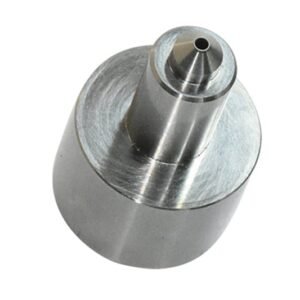
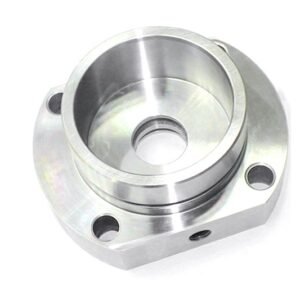
Representative Components for C110 Copper Development





Related Configurable Component Families and Quotation




Why Engineers Choose CNC Machining C110 Copper at SUUXIANG
A disciplined review and manufacturing workflow for C110 copper parts with clear priorities, controlled revisions, and inspection aligned to the order.
Drawing Review First
We review 2D drawings, models, material requirements, quantities, and application context before discussing a feasible machining route.
DFM for Copper
C110 copper’s softness and conductivity inform tool access, clamping approach, burr control, surface priorities, and practical feature sequencing.
Critical Dimension Planning
Critical-to-quality dimensions, datums, tolerance relationships, and surface requirements are identified so the process follows the functional design intent.
Process Route Coordination
CNC machining, EDM, grinding, fitting, and inspection are planned around geometry, allowances, access constraints, and stated project requirements.
Inspection Matched to Requirements
Inspection methods and reporting expectations are clarified against the drawing, critical features, and verified order requirements before production proceeds.
Visible Revision Control
Drawing revisions, manufacturing questions, and delivery information remain traceable, helping engineering and sourcing teams manage changes with confidence.
C110 Copper Machining Applications and Part Families
Drawing-driven process routes for copper parts, mold components, connector tooling, die components, and controlled prototype or low-volume requirements.

CNC Machining Services
Precision CNC machining services for drawing-based C110 copper and other verified-material parts. Review focuses on critical dimensions, datum strategy, tool access, burr control, surface requirements, quantity, and inspection expectations before quotation or production commitment.
Upload a Drawing
CNC Milling
Custom CNC milling services support prismatic copper parts, fixtures, inserts, plates, and complex machined features. Toolpaths, workholding, wall stiffness, corner radii, and burr-sensitive edges are reviewed against the drawing and functional requirements.
Upload a Drawing
CNC Turning
Precision CNC turning services support rotational parts such as pins, sleeves, bushings, contacts, and stepped cylindrical features. Concentricity, runout, thread requirements, surface finish, chucking strategy, and inspection datums should be defined before machining begins.
Upload a Drawing
5-Axis Machining
5-axis CNC machining supports multi-face features, angled geometry, deep pockets, and complex contours where fewer setups can protect datum relationships. Feasibility depends on tool access, fixture stability, material behavior, tolerance requirements, and inspection method.
Upload a Drawing
Swiss & Micro Machining
Swiss machining and micro machining support small-diameter, slender, and detail-intensive components where part support and feature sequence matter. RFQs should identify critical diameters, lengths, threads, cross holes, burr limits, material condition, and measurement requirements.
Upload a Drawing
Wire & Sinker EDM
Wire EDM and sinker EDM services address hardened materials, narrow slots, sharp internal geometry, fine profiles, and features with limited conventional tool access. Planning considers wire path, electrode design, flushing, recast-layer expectations, finishing passes, and downstream fitting.
Upload a Drawing
Precision Grinding
Precision surface and profile grinding supports controlled flatness, parallelism, profile accuracy, and finish on mold and die components. Grinding stock, heat-treatment sequence, datum surfaces, wheel access, and final inspection criteria should be resolved in the drawing review.
Upload a Drawing
Mold Core Inserts & Mold Cavity Inserts
Precision mold core and cavity inserts are produced from customer drawings and verified material specifications. Process planning may combine CNC machining, EDM, grinding, fitting, and inspection around shutoff surfaces, cooling features, molding geometry, and critical mating dimensions.
Upload a Drawing
Ejector & Ejection Components
Ejector pins, sleeves, and ejection components require attention to fit, straightness, surface condition, hardness requirements, lubrication paths, and mating-hole tolerances. Drawings should distinguish functional sliding dimensions from noncritical geometry and define required inspection evidence.
Upload a Drawing
Core Pins, Guide & Locating Components
Core pins, guide pins, bushings, and locating components are planned around functional alignment, wear surfaces, press or sliding fits, and repeatable assembly. Material, heat treatment, coating, grinding allowances, and mating-component datums should accompany the RFQ.
Upload a Drawing
Slides, Lifters, Gates & Mold Accessories
Mold slides, lifters, gates, and accessories are configurable tooling components requiring coordinated geometry and assembly interfaces. Review addresses travel direction, shutoffs, wear points, cooling or venting features, EDM access, fitting requirements, and revision-controlled mating data.
Upload a Drawing
Connector Mold Components
Precision connector mold components support fine-pitch, multi-cavity, and mating-feature tooling requirements. Manufacturing review considers pin or cavity geometry, datum relationships, material and hardness, EDM strategy, polish or texture requirements, and dimensional verification for assembled tooling.
Upload a Drawing
Stamping Die Components
Precision stamping die components include punches, die inserts, guide elements, plates, and forming details manufactured to drawing-defined requirements. Process planning considers tool steel condition, heat treatment, grinding stock, wire-EDM paths, clearance relationships, and inspection of critical profiles.
Upload a Drawing
Injection Mold Components, MIM, CIM & Overmolding Tooling
Injection, MIM, CIM, and overmolding tooling components are evaluated within verified production scope. A useful package identifies resin or feedstock context, parting and shutoff requirements, core and cavity geometry, thermal considerations, surface requirements, and assembly interfaces.
Upload a Drawing
Machining Materials
CNC machining materials are selected against drawing requirements, functional loads, corrosion environment, electrical or thermal needs, machinability, and downstream treatment. Material grade, condition, traceability expectations, and any approved substitution rules should be stated before quotation.
Upload a Drawing
Surface Finishes & Heat Treatment
Surface finishing and heat treatment are coordinated with dimensions, material grade, wear needs, corrosion exposure, conductivity, and appearance requirements. Specify treatment standard, target condition where applicable, masked areas, post-treatment grinding needs, and acceptance criteria.
Upload a Drawing
Quality, Metrology & Documentation
Precision inspection, metrology, and quality documentation are planned around critical dimensions, datums, sampling expectations, and customer reporting requirements. The order should define required records, such as dimensional reports, material evidence, revision status, and any agreed inspection format.
Upload a Drawing
Prototyping & Low-Volume Production
Rapid prototyping and low-volume manufacturing support drawing-based evaluation parts, bridge quantities, tooling trials, and controlled repeat requirements. Early review aligns material, process route, critical features, inspection scope, revision maturity, and target delivery date with the project needs.
Upload a DrawingMaterials for CNC Machining C110 Copper Projects

C110 Copper
High-conductivity copper for electrical contacts, bus components, thermal interfaces, and connector features. Its soft, ductile behavior requires controlled workholding, sharp tooling, burr management, and material evidence matched to the drawing.

Copper Alloys
Copper alloys can suit wear-sensitive, forming, or higher-strength component features where pure C110 is not the best fit. Grade chemistry, temper, conductivity, and mating conditions should be confirmed before machining strategy is released.

Stainless Steel
Stainless steel supports corrosion-resistant precision components, locating features, and tooling details. Grade, condition, heat-treatment state, and surface requirements affect cutting forces, grinding allowance, inspection planning, and final documentation.

Tool Steel
Tool steel is commonly specified for mold cores, inserts, pins, and stamping-die components requiring wear resistance. Machining sequence must account for hardness, heat treatment, EDM needs, grinding stock, and critical-dimension verification.

Aluminum Alloys
Aluminum alloys suit lightweight fixtures, prototype housings, thermal parts, and nonferrous tooling components. Alloy and temper affect chip control, rigidity, surface finish, anodizing compatibility, and the inspection criteria recorded for the order.
CNC Machining C110 Copper: Coordinated Finishing Processes

CNC Milling
CNC milling forms profiles, pockets, faces, and locating features in C110 copper and related precision components. Tool access, clamping, burr control, and datum sequence are reviewed to protect functional geometry and surface requirements.

CNC Turning
CNC turning supports rotational diameters, shoulders, bores, threads, and concentric features. The route is evaluated against part rigidity, material condition, runout requirements, and the inspection method specified for critical dimensions.

EDM Processing
Wire EDM and sinker EDM can address fine profiles, internal corners, narrow features, or hardened-tooling geometry when appropriate. Electrode strategy, wire path, recast-layer considerations, and downstream finishing requirements should be defined before production.

Precision Grinding
Precision grinding is planned for surfaces requiring controlled flatness, parallelism, size, or finish after machining or heat treatment. Grinding stock, datum protection, wheel selection, and measurement points are reviewed against the drawing.

Fitting Inspection
Fitting and inspection confirm how mating features, critical dimensions, and functional relationships perform against the agreed drawing revision. Reporting and traceability are aligned with the order’s inspection plan, not assumed from a generic template.
CNC Machining C110 Copper Component Features We Support

Copper Inserts
Drawing-specified C110 copper inserts can be machined as separate features or coordinated with mating components. Define interface dimensions, fit intent, retention method, surface requirements and inspection points before production planning.

Guide Features
Guide pins, bushings, locating shoulders and datum features help establish repeatable assembly relationships. Provide the mating-part drawing, positional tolerances, engagement length and wear considerations to support a practical machining and grinding route.

Ejection Elements
Ejector pins, sleeves, return elements and related clearances may be supplied where they are verified within the project scope. Identify travel, fit, hardness, surface condition and mold-interface requirements during drawing review.

Threaded Fasteners
Tapped holes, threaded inserts, dowel holes and specified fasteners require clear thread standards, depth limits, torque considerations and mating geometry. These details are reviewed alongside tool access and critical-dimension inspection requirements.

Part Identification
Part marks, revision identifiers, orientation marks and drawing-specified labels support traceability during assembly and receiving. Confirm marking method, location, legibility requirements and whether identification must appear in inspection or delivery documentation.

Assembly Hardware
Springs, set screws, retainers and other drawing-called hardware can be coordinated as project-specific component details. Share approved specifications, required quantities and assembly context so compatibility and documentation needs are reviewed before quotation.
About SUUXIANG Precision Manufacturing
SUUXIANG is the public-facing brand of Dongguan SuuXiang Precision Mold Co., Ltd., established in 2010 in Chang’an Town, Dongguan, Guangdong, China. We help international engineering, sourcing, and quality teams convert drawings and specifications into inspected custom parts, precision mold components, connector tooling, and die components.
Our production planning combines CNC milling and turning, multi-axis machining, EDM, precision grinding, fitting, and inspection. For cnc machining c110 copper and other drawing-based requirements, the route is defined around critical dimensions, datum strategy, tool access, surface expectations, and the inspection evidence required for the order.
What distinguishes SUUXIANG is an engineering-led workflow before commitments are made. We review DFM, material requirements, tolerance priorities, revision status, and delivery expectations so quotations and production plans reflect the actual part requirement. Manufacturing decisions remain traceable from drawing review through final inspection documentation.

CNC Machining C110 Copper: From Drawing Review to Inspection
DFM Before Commitment
SUUXIANG reviews the drawing, model, C110 copper condition, quantity, datums, and functional interfaces before quotation. The discussion identifies thin sections, burr-sensitive edges, tool access, and tolerance relationships so the proposed route reflects the actual part requirement.
- Confirm drawing revision and critical dimensions
- Review datum strategy and tolerance stack
- Identify burr, deformation, and clamping risks
- Clarify material, quantity, and delivery requirements

Select the Right Process Route
CNC machining C110 copper may require more than milling or turning alone. SUUXIANG evaluates feature geometry, internal corners, surface requirements, and finishing allowances to determine where CNC machining, wire EDM, sinker EDM, or precision grinding adds practical value.
- Match process to feature accessibility
- Plan EDM for sharp internal geometry
- Reserve grinding for controlled surfaces
- Account for machining and finishing allowances

Control Critical Dimensions
Critical features are considered in relation to their datums, mating conditions, and inspection method. For C110 copper parts, this helps prevent measurement ambiguity and supports a realistic plan for dimensions affected by clamping, machining sequence, or delicate geometry.
- Define CTQ dimensions and datum references
- Sequence operations around functional features
- Consider fixture influence on thin geometry
- Align measurement method with tolerance intent

Plan Traceable Inspection
Inspection planning is established against the approved drawing and project requirements. SUUXIANG keeps revision information, measurement priorities, and requested reporting visible through production coordination, helping buyers receive documentation that corresponds to the verified inspection plan and order scope.
- Link inspection points to drawing revision
- Agree reporting and documentation needs
- Verify critical features against the plan
- Maintain visible revision and delivery coordination

CNC Machining C110 Copper: Beyond a Quote-Only Supplier
Compare the review, communication, revision, and inspection evidence needed before committing custom C110 copper parts to production.
← Swipe left or right to view →
CNC Machining C110 Copper Production Workflow
A controlled project path for drawing-driven copper components, from manufacturability review through documented inspection and delivery coordination.
Review Drawings and Requirements
We review 2D drawings, 3D models, C110 copper specification, quantity, critical dimensions, datums, surface requirements, inspection needs, and target delivery expectations.
Confirm DFM and Process
The team identifies machining access, clamping approach, tolerance risks, burr-control requirements, and whether EDM or grinding supports the specified feature strategy.
Plan Materials and Production
After requirements are clarified, SUUXIANG coordinates material verification, process routing, programming, tooling, revision control, and a project-specific inspection plan before release.
Machine Critical Part Features
CNC milling, turning, multi-axis machining, EDM, or grinding are applied according to the approved route, with attention to copper deformation and feature protection.
Inspect Pack and Coordinate
Finished parts are inspected against the agreed plan, protected for shipment, and released with order-matched documentation and visible delivery coordination.
Customer Evidence Publication Requirements
Give our team the technical context needed to review manufacturability, align inspection expectations, and release your C110 copper parts with controlled revision information.
Submit Your Drawing Package
Upload the 2D drawing, 3D model when available, material specification, quantity, application context, target date, and required inspection or reporting documentation.
Review DFM and Requirements
Confirm critical dimensions, datums, surface requirements, machining access, tolerance stack, heat-treatment sequence, and any EDM, grinding, or inspection considerations before quotation.
Approve Quote and Sample
Review the proposed process route, commercial inputs, and revision details; where required, approve a sample or first article against the agreed inspection plan.
Release Controlled Production
Authorize production after requirements are aligned. SUUXIANG coordinates machining, finishing, inspection, and delivery against the released drawing revision and documented quality expectations.
Certification and Quality Documentation
CNC Machining C110 Copper: Verified Project Feedback
Customer testimonial publication requires documented project results, confirmed quotation or inspection evidence, and written client permission before SUUXIANG presents performance, delivery, dimensional, or quality outcomes as a customer statement.
Before publishing a CNC machining C110 copper case outcome, SUUXIANG confirms the approved wording, relevant drawing revision, measurable result, and whether the client name, application, and company identity may be disclosed.
Approved feedback should identify the specific manufacturing scope and evidence behind it, such as inspection reporting, critical dimensions, material requirements, quantity, or delivery coordination, without exposing confidential part or program details.
CNC Machining C110 Copper FAQ
Practical guidance for quoting, quality planning, delivery coordination, and confidential drawing-based production.
What is the MOQ for cnc machining c110 copper parts?
Can SUUXIANG review my drawing before quoting cnc machining c110 copper?
Do you provide samples before production for cnc machining c110 copper?
What affects lead time for custom C110 copper machined parts?
What payment terms are available for a custom machining order?
Can SUUXIANG arrange international shipping?
Can I request inspection reports with my order?
How does SUUXIANG protect drawings and intellectual property?
Complete Buyer’s Guide to cnc machining c110 copper
Use this decision framework to specify C110 copper parts, compare machining and supplier capabilities, control cost and quality risk, and avoid drawing, tooling, inspection, and sourcing mistakes before production.
1. What Is cnc machining c110 copper?
C110, commonly called electrolytic tough-pitch copper, is a high-purity copper grade valued for electrical and thermal conductivity. In cnc machining c110 copper, a shop converts the released drawing and model into dimensioned parts through milling, turning, drilling, EDM where justified, and inspection against defined datums.
100% IACS is the conventional reference conductivity for annealed pure copper, so C110 is commonly specified for connector contacts, busbars, electrodes, heat-transfer inserts, and conductive mold details. Its softness and ductility require the drawing to identify critical features, burr limits, flatness, surface condition, and any post-machining forming or plating needs.
Brass is often the better choice when easier machining, strength, or thread durability outweigh conductivity; bronze may suit wear-loaded or bearing features. Other copper grades should be considered when the application requires improved high-temperature behavior, weldability, corrosion resistance, or a controlled oxygen content rather than C110’s conductivity-first balance.
2. C110 Copper Background and Industrial Uses
C11000, commonly specified as electrolytic tough-pitch copper, is a commercially pure copper grade long used where high electrical and thermal conductivity matters. Its industrial legacy spans busbars, electrical contacts, heat-transfer hardware, welding electrodes, and connector-related components.
By the late 19th century, copper had become foundational to electrical distribution as power and telecommunications networks expanded. That history still matters to buyers: a connector contact, thermal spreader, or tooling insert must be evaluated against its actual current path, heat load, mating geometry, and drawing-defined inspection requirements.
Five-axis milling, precision turning, EDM, and grinding have extended cnc machining c110 copper beyond simple bar or plate forms into low-volume, geometry-specific parts. For complex components, the drawing review should establish datums, thin-wall support, burr-control expectations, tool access, and any required mating or assembly context before the production route is selected.
3. Types of cnc machining c110 copper Parts
C110 copper drawings usually fall into rotational, prismatic, contact, electrode, tooling, or assembly work. Classifying geometry first clarifies the process route, datum plan, and inspection priorities.
Turned Pins And Terminals
C110 pins, terminals, and sleeves use diameters, shoulders, tapers, and concentric features. Swiss turning or CNC turning suits long, small-diameter geometry; control mating diameters, runout, burr direction, and contact surfaces.
Connector terminals may add cross-holes, slots, or flats. Use live tooling or a secondary milling operation when these features reference the turned datum.
Milled Plates And Contacts
C110 busbars, contact blades, and cooling plates are prismatic parts with pockets, holes, and edge profiles. CNC milling supports flatness-sensitive faces, hole location, and controlled tool access around thin sections.
Connector contacts often require narrow slots and consistent spring geometry. Specify the functional datum and mating zone before selecting cutters and deburring strategy.
Electrodes, Inserts, And Assemblies
C110 EDM electrodes combine shaped faces, fine ribs, and datum features; multi-axis milling can establish the electrode form. Inspect critical geometry against the burn allowance and electrode reference scheme.
C110 mold inserts and prototype assemblies may combine milled, turned, ground, and EDM features. Review interface dimensions, fastener access, assembly stack-up, and reporting requirements before release.
4. C110 Material Conditions and Alternatives
C110 is commonly specified as electrolytic tough-pitch copper, but form and temper must be ordered with the drawing. For cnc machining c110 copper, stock selection changes residual stress, clamping stability, and material lead time.
| Material | Conductivity | Oxygen | Machining | Joining | Cost |
|---|---|---|---|---|---|
| C110 | ~100% IACS | Typical ETP | Difficult chips | Avoid hydrogen heat | Baseline |
| C101 | ~101% IACS | Very low | Difficult chips | Best for welding | Higher |
| C102 | ~100% IACS | Low | Difficult chips | Good brazing | Higher |
| C145 | 75–85% IACS | Grade-dependent | Improved chips | Qualify process | Higher |
| Brass | 25–30% IACS | Not key | Easy | Generally good | Lower |
| Bronze | 10–20% IACS | Not key | Moderate | Process-dependent | Variable |
Forms And Tempers
Bar stock suits turned pins and round features; plate supports milled inserts and bus bars.
Sheet favors formed blanks, while tube is practical only when wall, concentricity, and sourcing are confirmed.
Starting Stock Risks
Cold-worked tempers generally machine more cleanly than annealed copper, but can spring after heavy stock removal.
Stress-relieved plate and flatness requirements should be reviewed before machining thin pockets or sealing faces.
Alternative Selection
C101 or C102 is preferable where hydrogen-safe welding, vacuum service, or maximum conductivity matters.
C145 improves chip control; brass lowers cost for moderate conductivity, and bronze is stronger for wear-bearing duties.
5. Finishes for cnc machining c110 copper
C110 copper forms oxide films quickly in air, changing color and potentially raising interface resistance. Specify the finish as part of the functional stack, not as a cosmetic afterthought.
| Finish | Primary Effect | Key Trade-Off |
|---|---|---|
| Bare, protected | Best conductivity | Oxidizes and fingerprints |
| Tin | Solderable protection | Soft; dimensional buildup |
| Nickel | Wear and barrier | Higher contact resistance |
| Silver or gold | Low-resistance contacts | Cost; specify thickness |
Prepare The Base Metal
0.1 mm edge breaks or a drawing-defined deburr limit prevent raised burrs from disrupting plating and mating. Polishing improves appearance but can round sealing lands and remove dimensional control.
24-hour dry, clean handling after machining reduces fingerprints and staining before shipment or plating. Use protective packaging when bare copper is acceptable, but oxidation risk remains.
Select Functional Plating
2–10 µm tin is commonly chosen for solderability and economical corrosion protection. Nickel provides a harder barrier layer, while silver and gold can support low-resistance contact duties when the application specification supports them.
Selective plating limits cost and buildup on non-contact surfaces. Define masked areas, rack marks, and whether nickel underplate is required.
Control The Drawing Callout
5 µm of deposited coating changes each plated surface and can affect tight fits, threads, and contact geometry. State thickness, measurement location, base-metal condition, and whether dimensions apply before or after plating.
1 inspection plan should identify adhesion, thickness, appearance, and contact-critical verification. Include solderability, corrosion, or wear tests only when the relevant product standard defines them.
6. Critical Quality Elements in C110 Parts
0.05 mm edge breaks can prevent handling cuts and uncontrolled burr rollover on small C110 features. For cnc machining c110 copper, usable quality begins with drawing-defined datums, edge conditions, and inspection criteria.
Edges And Surface Control
0.1 mm maximum burr height is a practical drawing requirement when mating, plating, or electrical contact is sensitive. Specify chamfer, radius, or an explicitly sharp edge; visual inspection should check tool marks, smeared material, and trapped burrs.
Clamping And Thin Walls
Two-sided machining can distort thin C110 walls if clamping load or stock removal is unbalanced. Define datum faces before re-clamping, use supported workholding, and inspect wall thickness after release rather than while constrained.
Datums Threads And Verification
Three datum references should govern positional tolerances whenever a part mates to a housing, insert, or connector feature. CMM inspection verifies datum-related geometry; pin gauges check bores, thread gauges verify threads, and specified conductivity or plating tests require recorded acceptance criteria.
7. Choosing cnc machining c110 copper Suppliers
Two supplier responses can quote the same drawing yet reveal different control plans. For cnc machining c110 copper, compare production evidence before unit price.
Verify Material Traceability
One material lot should link the purchase record, mill certificate, and part traveler. Ask whether C110 condition, heat, and stock dimensions remain traceable after cutting.
- Mill certificate available
- Lot linked to traveler
- Condition recorded
Test Drawing Understanding
Three questions expose machining depth: which datums drive setup, what fixture prevents distortion, and where are burrs controlled? Request marked-up DFM identifying tool access, clamping, inspection points, and tolerance risks.
- Datum-based setup plan
- Fixture concept supplied
- Burr-control approach
Confirm Production Control
First-article sample approval should precede volume release. Ask for in-process checks, final dimensional reports, plating documentation, and the accountable plating partner.
Two operational checks matter: confirm equipment fit, copper-machining experience, available capacity, and a named revision-response owner.
- First-article report
- In-process records
- Revision communication
8. Common C110 Copper Sourcing Mistakes
C110 copper releases fail most often when drawings leave material, geometry, or acceptance criteria open to interpretation. For cnc machining c110 copper, resolve those decisions before quotation and retain them through revision control.
Material And Temper Mismatch
C110 identifies an alloy family, but temper and conductivity requirements still affect forming response and functional performance. State the exact material standard, condition, traceability need, and any approved substitute before release.
Undefined Datums And Edges
0.05 mm can be critical only when its datum scheme is defined; isolated dimensions invite stack-up disputes. Call out burr limits, edge breaks, protected contact areas, and inspection method so assembly interfaces remain safe and repeatable.
Incomplete Plating Requirements
1 plating note without thickness, coverage, adhesion, masking, or post-plate inspection criteria can produce a visually acceptable but electrically unsuitable part. Specify the coating system, minimum thickness location, preparation, and functional test required.
Unsupported Features And Price
Thin copper webs deflect, smear, and retain burrs differently from steel, especially near deep pockets or small threads. Review tool access and support strategy, then compare unit price with inspection evidence, yield risk, revision handling, and delivery control.
9. From Drawing Review to Production Launch
2D drawings, 3D models, mating context, quantity, and target date should enter the RFQ together. One controlled revision record prevents C110 copper requirements from changing between quote and launch.
| Team | Approval Document | Release Decision |
|---|---|---|
| Engineering | Drawing, model, CTQs | Functional acceptance |
| Procurement | PO, quantity, target date | Commercial release |
| Supplier Quality | Inspection plan, sample report | Quality release |
Review The Manufacturing Route
One DFM response should identify datum use, tool access, burr-sensitive edges, clamping risk, and the proposed CNC, EDM, or grinding sequence.
Two records must be confirmed before sampling: material condition and finish requirement, including any conductivity, plating, or handling constraint.
- Engineering approves functional requirements and CTQs.
- Procurement confirms quantity, commercial scope, and delivery target.
- Supplier quality reviews measurable acceptance criteria.
Approve Samples And Release
One first-article or agreed sample approval should compare measured critical dimensions with the released drawing and inspection plan.
Each pilot-production authorization should name the approved revision, lot quantity, reporting requirement, and disposition path for nonconforming parts.
- Approve drawing and 3D-model revision.
- Approve DFM and material specification.
- Approve inspection plan and sample results.
- Release pilot production, then production order.
10. cnc machining c110 copper Pricing and Lead Times
1-piece C110 copper prototypes often carry the highest unit cost because CAM programming, workholding, first-article inspection, and material preparation are spread across one part. A reviewed 2D drawing, 3D model, alloy condition, quantity, tolerances, finish, and inspection requirement are necessary before any price is dependable.
3 factors usually dominate machining cost: stock form and yield, cycle time, and tolerance-driven scrap risk. Thin walls, deep pockets, burr-sensitive edges, special finishing, tight positional requirements, and expanded reports add handling or verification time.
5- to 15-business-day planning windows are common for straightforward orders after technical approval, but procurement should treat them as quote-stage ranges. SUUXIANG should confirm the process route, material availability, inspection plan, revision status, and delivery commitment against the current drawing package.
| Quantity tier | Representative unit-price range, USD | Setup or programming impact | Typical lead-time range |
|---|---|---|---|
| 1–5 pieces | $60–$300+ | Highest per-part setup allocation | 7–15 business days |
| 10–50 pieces | $25–$150+ | Setup spread across batch | 10–20 business days |
| 100+ pieces | Quote required | Fixture, inspection, and repeatability review | 15–30+ business days |
Start CNC Machining C110 Copper With a Drawing Review
Submit your drawing, model, material requirements, quantity, critical dimensions, inspection needs, and target date for a disciplined manufacturing review.