
CNC Machining Polycarbonate for Inspected Precision Parts
Submit your drawing for polycarbonate machining with DFM review, critical-dimension planning, and inspection aligned with order requirements.
Representative Components and Tooling Examples





Request a Drawing-Based Quote


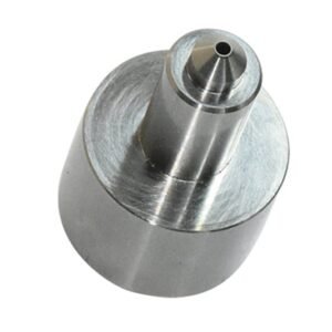


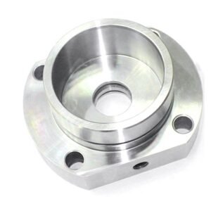


Why Engineers Specify SUUXIANG for CNC Machining Polycarbonate
A drawing-led workflow for polycarbonate parts where machining strategy, critical dimensions, inspection requirements, and revisions must remain visible.
Drawing-Led DFM
We review geometry, datums, wall conditions, tool access, and finish priorities before quotation so manufacturability questions are addressed early.
Heat-Aware Process Planning
Tooling, workholding, chip control, and cutting strategy are considered together to help manage heat-related surface and dimensional risks.
Critical Dimensions First
Your drawing’s functional dimensions, mating features, and tolerance stack guide the machining sequence and inspection focus for CNC machining polycarbonate.
Practical Tool Access
We identify deep pockets, small features, internal corners, drilling paths, and clamping concerns that can affect part design or process route.
Inspection Plan Alignment
Measurement methods and reporting expectations are defined against the order requirements, helping align final documentation with the verified inspection plan.
Revision Visibility
Drawing revisions, clarified requirements, and delivery coordination remain visible throughout the project to support controlled communication between engineering and sourcing teams.
Precision Components Built From Your Drawing
Explore configurable process and component families, each planned around critical dimensions, material requirements, inspection needs, and the production route supported by your project evidence.

CNC Machining Services
Precision CNC machining services for drawing-based parts requiring coordinated milling, turning, EDM, grinding, fitting, and inspection. Drawing review identifies critical dimensions, datum strategy, material requirements, and practical process risks before quotation or production planning.
Upload a Drawing
CNC Milling
Custom CNC milling services for prismatic parts, mold plates, inserts, and features requiring controlled tool access. Reviews address machining sequence, wall conditions, pocket geometry, surface priorities, and allowance for downstream EDM, grinding, or heat treatment.
Upload a Drawing
CNC Turning
Precision CNC turning services for shafts, pins, sleeves, bushings, and rotational components. Provide drawings with diameter tolerances, concentricity requirements, threads, surface requirements, material condition, and any features requiring secondary milling, EDM, or grinding.
Upload a Drawing
5-Axis Machining
5-axis CNC machining supports complex contours, angled features, and multi-face parts where fewer setups can improve feature relationships. Feasibility depends on tool reach, clamping strategy, datum access, material, tolerance requirements, and inspection method.
Upload a Drawing
Swiss & Micro Machining
Swiss machining and micro machining support small-diameter, high-detail components such as pins, sleeves, connector features, and miniature turned parts. Review dimensional priorities, burr limits, material behavior, handling requirements, and measurement strategy before routing work.
Upload a Drawing
Wire & Sinker EDM
Wire EDM and sinker EDM services address hardened materials, internal profiles, narrow features, sharp internal corners, and intricate cavities. Process planning considers wire path or electrode strategy, flushing access, recast-layer requirements, finishing allowances, and inspection points.
Upload a Drawing
Precision Grinding
Precision surface and profile grinding supports flatness, parallelism, profile control, and final-size work after machining or heat treatment. Drawings should define datums, critical relationships, surface requirements, stock condition, and measurement expectations.
Upload a Drawing
Mold Core & Cavity Inserts
Precision mold core and cavity inserts are configured from part geometry, resin behavior, cooling needs, and mold-layout constraints. Reviews address shutoffs, steel selection, EDM access, grinding allowances, critical interfaces, and inspection requirements for fitting.
Upload a Drawing
Ejector & Ejection Components
Ejector pins, sleeves, and ejection components are produced to the mating mold design and required movement conditions. Define diameters, clearance relationships, hardness requirements, surface condition, lubrication considerations, and any fit or inspection criteria.
Upload a Drawing
Core Pins, Guide & Locating Components
Core pins, guide pins, and locating components require disciplined control of mating dimensions and datum relationships. Supply interface drawings, material and heat-treatment requirements, fit class, runout or positional priorities, and the related mold-component context.
Upload a Drawing
Slides, Lifters, Gates & Mold Accessories
Mold slides, lifters, gates, and accessories are planned as configurable components within the complete mold mechanism. Review travel, locking and wear interfaces, shutoff conditions, material treatment, machining access, fitting requirements, and critical assembly dimensions.
Upload a Drawing
Connector Mold Components
Precision connector mold components support fine-pitch geometry, pin and cavity relationships, insert interfaces, and repeatable assembly. Manufacturing planning focuses on critical dimensions, electrode or wire-EDM strategy, material condition, surface requirements, and inspection evidence.
Upload a Drawing
Stamping Die Components
Precision stamping die components include punches, dies, guides, inserts, and custom elements made to the working die design. Reviews consider material, hardness sequence, cutting-edge geometry, clearance relationships, grinding stock, wear surfaces, and assembly fit.
Upload a Drawing
Injection, MIM, CIM & Overmolding Tooling
Injection, MIM, CIM, and overmolding tooling components are evaluated against the molding process, part geometry, material behavior, and tool architecture. Confirm cavity details, interfaces, venting or gating needs, steel requirements, dimensional priorities, and verification expectations.
Upload a Drawing
Machining Materials
CNC machining materials are selected against function, machinability, stability, wear, corrosion exposure, and downstream treatment. State the specified grade, condition, approved substitution rules, traceability needs, and any application constraints before production commitment.
Upload a Drawing
Surface Finishes & Heat Treatment
Surface finishing and heat treatment are planned as part of the dimensional route, not an afterthought. Identify finish type, roughness or cosmetic requirements, coating or treatment specification, masking needs, hardness target, and dimensions affected by processing.
Upload a Drawing
Quality, Metrology & Documentation
Precision inspection, metrology, and quality documentation are aligned with the approved drawing and inspection plan. Define critical dimensions, datum references, sampling or reporting requirements, measurement methods, revision level, material evidence, and required traceability records.
Upload a Drawing
Prototyping & Low-Volume Production
Rapid prototyping and low-volume manufacturing support drawing revisions, functional evaluation, pilot builds, and controlled repeat orders. Submit the latest 2D drawing, 3D model when available, quantity, material, quality requirements, delivery target, and revision history.
Upload a DrawingCNC Machining Polycarbonate: Grades and Material Considerations

Clear General-Purpose PC
A transparent, tough grade for guards, covers, lenses, and inspection windows. It offers a smooth visual appearance and strong impact performance, but machining heat, tool marks, and surface-scratch requirements should be reviewed early.

Translucent Polycarbonate
A light-diffusing PC option for illuminated covers, bezels, and non-clear protective housings. Its softer visual appearance helps distribute light, while wall thickness, finish expectations, and color consistency should be defined on the drawing.

Black Polycarbonate
An opaque engineering grade suited to housings, fixtures, internal components, and light-blocking features. It retains PC toughness without an optical-clarity requirement, allowing the review to focus on datum strategy, fit, and machined surface condition.

Glass-Filled Polycarbonate
A reinforced PC grade for parts needing increased stiffness and improved resistance to deformation under load. The material is less suited to transparent applications, and fiber orientation, tool wear, edge condition, and tolerance priorities require review.

Flame-Retardant Polycarbonate
A specialized PC option for electrical or connector-related applications where specified flame-performance requirements matter. Confirm the exact resin grade, color, documentation needs, machining features, and any application-specific compliance requirements before quotation.
CNC Machining Polycarbonate: Process Routes and Finishing

CNC Milling
CNC milling forms profiles, pockets, holes, and datum-related features in polycarbonate. Tool geometry, chip evacuation, workholding, and heat control are reviewed to reduce stress, edge damage, and visible machining marks.

CNC Turning
For rotational polycarbonate parts, CNC turning establishes diameters, bores, shoulders, and threaded-feature preparations. The process plan considers wall stiffness, clamping forces, runout requirements, and finish expectations before production is committed.

EDM Tooling Support
Wire EDM or sinker EDM may support associated conductive tooling, electrodes, fixtures, or mating mold components rather than the nonconductive polycarbonate workpiece itself. Electrode strategy and interface requirements are confirmed from the project drawing.

Precision Grinding
Grinding can support controlled finishing of applicable fixtures, tooling, or mating precision components. Where a polycarbonate feature requires refinement, SUUXIANG reviews stock allowance, heat sensitivity, datum control, and inspection method before selecting the approach.

Edge Finishing
Deburring and selected finishing steps address sharp edges, tool marks, and handling-sensitive surfaces. Required appearance, clarity, scratch sensitivity, and mating conditions should be defined on the drawing or RFQ so the result matches its intended use.
CNC Machining Polycarbonate Hardware and Interface Features

Threaded Inserts
Heat-set or press-fit insert requirements should define thread size, installation method, pullout expectations and surrounding wall geometry. SUUXIANG reviews boss dimensions, access and datum relationships before committing to a process route.

Locating Pins
Dowel, guide and alignment pins establish repeatable position between polycarbonate parts and mating assemblies. Identify fit class, insertion depth, positional tolerance and whether the pin is supplied, installed or measured separately.

Captive Fasteners
Captive screws, nuts and washers can simplify service access while adding local loading to the component. Provide the fastener specification, retention detail, tightening condition and mating-stack information for drawing review.

Identification Labels
Labels, markings and traceability identifiers require a defined location, surface condition and durability expectation. Include artwork, application method and any inspection requirement so cosmetic surfaces and functional datums remain protected.

Mating Interfaces
Mating faces, slots, windows and connector interfaces must be evaluated with the companion-part geometry. Share interface dimensions, datum scheme, clearance targets and assembly sequence to support a practical machining and inspection plan.
About SUUXIANG Precision Manufacturing
SUUXIANG is the sole public-facing brand of Dongguan SuuXiang Precision Mold Co., Ltd., established in 2010 and based in Chang’an Town, Dongguan, Guangdong, China. Founded and legally represented by XiaoCheng Huang, the company helps international engineering and sourcing teams convert drawings and specifications into inspected custom machined parts, precision mold components, connector tooling, and stamping-die components.
Our drawing-driven workflow combines CNC milling and turning, multi-axis machining, EDM, precision grinding, fitting and inspection. For cnc machining polycarbonate and other custom part requirements, the process begins with DFM, critical dimensions, datums, material requirements, machining access and inspection expectations—not assumptions.
What distinguishes SUUXIANG is disciplined project coordination around the details that affect part acceptance: revision control, machining allowance, EDM or grinding strategy, measurement method and delivery documentation. Share a 2D drawing, 3D model when available, material, quantity and quality requirements to begin a technically grounded review.

CNC Machining Polycarbonate: Critical Capability Review
DFM Before Process Commitment
SUUXIANG reviews the drawing, 3D model, PC grade, critical dimensions, datums, surface priorities, quantity, and application context before proposing a CNC machining polycarbonate route. This identifies avoidable risks before quotation or production commitments are made.
- Confirm critical-to-quality dimensions and datum references
- Review wall transitions, radii, threads, and feature relationships
- Identify material, heat, finish, and reporting requirements
- Record revisions and open manufacturing questions

Tool Access and Workholding
Clear polycarbonate and engineered PC grades require process planning that considers tool reach, part support, clamping pressure, chip evacuation, and heat generation. SUUXIANG evaluates inaccessible features and distortion risk so the machining sequence matches the drawing’s functional priorities.
- Check cutter reach for pockets, ribs, and deep features
- Plan support for thin walls and flexible geometries
- Review hole locations, edge distances, and deburring access
- Define practical surfaces for controlled workholding

EDM and Grinding Decisions
Where a drawing combines polycarbonate components with precision mold or connector-tooling features, SUUXIANG separates the required process routes. EDM and grinding are considered only where the specified material, geometry, hard condition, and critical-feature strategy justify those processes.
- Distinguish plastic-part machining from tooling-component requirements
- Review wire paths, electrode access, and relief features
- Define grinding stock and datum transfer where applicable
- Align process sequence with material-condition requirements

Inspection Plan From Datums
For cnc machining polycarbonate, inspection planning starts with the agreed drawing revision and measurement method. SUUXIANG aligns critical dimensions, datum strategy, cosmetic expectations, and requested records with an inspection plan that can be reviewed before final delivery.
- Identify dimensions requiring documented verification
- Match measuring methods to feature geometry and tolerance intent
- Clarify visual acceptance criteria for machined surfaces
- Maintain revision traceability through production and inspection

CNC Machining Polycarbonate: Beyond Quote-First Sourcing
Compare a disciplined drawing-review workflow with generic quote-first sourcing before releasing critical polycarbonate parts.
← Swipe left or right to view →
CNC Machining Polycarbonate Production Workflow
A drawing-driven path that aligns material requirements, critical dimensions, machining strategy, inspection evidence, and delivery coordination before production commitments are made.
Review RFQ Package
SUUXIANG reviews the 2D drawing, 3D model, quantity, application, delivery target, and inspection requirements to clarify the production scope before quotation.
Confirm Material And DFM
The team confirms the specified polycarbonate grade, critical dimensions, datum strategy, surface priorities, tool access, workholding risks, and feasible inspection approach.
Plan Machining Route
Process planning defines CNC operations, machining allowance, toolpath sequence, protective handling for cosmetic surfaces, and any required fitting or secondary operations.
Machine And Control Revisions
Parts are machined to the approved drawing revision, with project communication focused on identified questions or changes that affect dimensions, finish, or delivery.
Inspect Pack And Coordinate
Completed parts are verified against the agreed inspection plan, packed to protect relevant surfaces, and prepared with order-matched documentation and delivery coordination.
How CNC Machining Polycarbonate Projects Move Forward
A controlled engagement sequence for custom polycarbonate parts, from drawing review through inspection and delivery coordination.
Submit Your Requirements
Provide your 2D drawing and 3D model, material grade, quantity, critical dimensions, surface priorities, delivery target, and inspection documentation requirements.
Review DFM and Quotation
Review manufacturability, datum strategy, tool access, machining sequence, tolerance priorities, finishing needs, and quotation assumptions before approving the production route.
Approve Samples When Needed
For higher-risk or revision-sensitive cnc machining polycarbonate parts, confirm sample, first-article, or agreed inspection evidence before the production release.
Track Production and Delivery
Coordinate machining, deburring, inspection, revision status, and delivery details against the agreed order requirements and verified inspection plan.
Quality Documentation and Certification Evidence
Customer References Available Upon Approval
Verified customer case study pending approval. This card will document the drawing-review outcome, agreed critical dimensions, inspection evidence, revision-control record, and delivery coordination for a completed polycarbonate component project.
Verified customer case study pending approval. This card will summarize a CNC machining polycarbonate project, including the approved drawing revision, material specification, dimensional priorities, inspection plan, and documented production outcome.
Verified customer case study pending approval. This card will capture the customer’s confirmed feedback on component quality, communication milestones, delivery coordination, and any measurable result supported by the completed order record.
CNC Machining Polycarbonate FAQ
Practical answers for engineering and sourcing teams preparing drawing-based PC parts for review.
What files should I send for polycarbonate machining?
Which PC grade should I specify for cnc machining polycarbonate?
What tolerances are realistic for cnc machining polycarbonate?
Can cnc machining polycarbonate produce optically clear parts?
Do you provide first-article samples before a low-volume order?
What inspection report can accompany polycarbonate machined parts?
How should I plan lead time for a polycarbonate machining RFQ?
How are shipping and IP handled for custom CNC parts?
The Complete Buyer’s Guide to cnc machining polycarbonate
Use this decision framework to specify suitable PC grades, control machining and finish risks, evaluate drawing-review suppliers, compare cost drivers, and avoid sourcing mistakes that delay functional prototypes and low-volume production.
1. What Is cnc machining polycarbonate?
PC, or polycarbonate, is an engineering thermoplastic machined from sheet or bar through controlled CNC milling, turning, drilling, routing, and related subtractive operations. The process creates drawing-defined pockets, holes, profiles, threads, and mating interfaces.
Two project stages commonly suit polycarbonate machining: rapid functional prototypes and low-volume bridge or production parts where tooling investment is not yet justified. Buyers select PC when impact toughness, useful clarity, dimensional stability, and electrical insulation matter alongside repeatable geometry.
Clear stock and a clear-looking finished part are not the same requirement. Tool marks, scratches, and machining-induced surface condition can limit optical performance, so drawings should specify any polishing, finishing, or viewing-zone expectation.
2. How Polycarbonate Machining Evolved
Sheet and bar stock were the practical starting point for many polycarbonate components: cut panels, simple guards, formed covers, and machined blocks. Geometry was constrained by manual layout, basic fixturing, tool access, and the need to avoid heat damage or visible edge defects.
3-axis CNC control expanded the role of CNC machining polycarbonate into drawing-defined prototypes, nestable fixtures, enclosures, interfaces, and transparent industrial details. Repeatable toolpaths made pockets, drilled patterns, radii, and mating features more practical, provided the setup supports the part without distorting it.
Sharp plastic-cutting tools, purpose-built workholding, and controlled post-processing changed finish expectations as much as geometry. A current RFQ should therefore identify the required clarity zone, cosmetic faces, datum scheme, wall sections, fastener loads, and inspection method; machining alone does not automatically produce an optical finish.
3. Types of cnc machining polycarbonate
Process selection begins with stock form and feature access. Choose machined-from-solid PC for integral precision features; specify bent, bonded, or assembled sheet construction separately because its joint and formed geometry require a different route.
CNC Milling
Three-axis milling suits prismatic housings, pockets, windows, and mounting faces. Provide datums, wall zones, corner radii, stock form, and critical dimensions; deep narrow pockets may limit tool access.
CNC Turning
Rotary parts such as bushings, lenses, collars, and threaded caps suit turning from bar or tube. Provide diameters, concentricity datum, bore details, runout requirements, and whether cosmetic surfaces are functional.
Drilling And Tapping
Holes, counterbores, and inserts commonly follow milling or turning. Specify thread standard, engagement length, insert type, hole datum, and whether fastening loads require a metal insert.
Sheet-Part Routing
Flat panels, guards, and simple profiles suit routing from sheet. Provide thickness, edge-quality requirement, hole pattern, protective-film instruction, and any later bends, bonds, or assembled joints.
Multi-Axis Machining
Five-axis access suits angled ports, compound contours, and features requiring fewer re-clamps. Provide the 3D model, datum scheme, inaccessible-surface definition, and inspection method before selecting this higher-complexity route.
4. Polycarbonate Grades and Stock Forms
Polycarbonate selection starts with the resin designation, not the generic label PC. Confirm the exact grade, color, stock form, and required certificate before cnc machining polycarbonate begins.
| Grade Or Form | Toughness/Clarity | Stiffness/Thermal Fit | Machining/Application |
|---|---|---|---|
| Clear general-purpose | High / clear | Balanced | Guards, housings |
| Black or translucent | High / limited clarity | Balanced | Covers, light control |
| Optical grade | High / highest clarity | Application-specific | Lenses, viewing parts |
| Flame-retardant | Grade-dependent / limited | Electrical thermal needs | Electrical housings |
| Glass-filled | Reduced clarity | Higher stiffness | Rigid structural parts |
| Sheet vs rod/bar | Same resin-dependent | Geometry-dependent | Panels vs turned parts |
Clear And Colored Grades
Clear general-purpose PC combines high toughness with useful clarity for guards and housings. Black or translucent grades suit light control, covers, and non-optical assemblies.
Performance-Modified Grades
Optical-grade PC prioritizes controlled clarity, but machined surfaces may still need a specified finishing route. Flame-retardant PC suits electrical applications only when the required rating and resin documentation are confirmed.
Glass-filled PC raises stiffness and reduces transparency; it can also change tool wear, edge quality, and finishing expectations.
Match Stock To Geometry
Sheet stock favors flat profiles, panels, and broad pockets; rod or bar favors turned diameters and compact blocks. Verify supplier stock thickness, orientation, internal stress condition, and traceable resin grade before release.
5. Finishes for cnc machining polycarbonate
Finish selection for cnc machining polycarbonate must be tied to the drawing’s optical, cosmetic, scratch-resistance, and assembly requirements. SUUXIANG should review finish-critical surfaces before releasing the process route.
| Finish | Cosmetic Clarity | Dimensional Risk | Validate |
|---|---|---|---|
| As-machined | Low | Low | Tool-mark limit |
| Mechanical polish | Medium | Medium | Edge geometry |
| Vapor polish | High potential | Medium | Clarity and cracking |
| Hard coating | Preserved clarity | Low on base part | Adhesion and scratch test |
As-Machined, Deburred, And Polished
An as-machined surface retains tool marks but has the lowest dimensional intervention. Deburring removes sharp edges; wet sanding and mechanical polishing can improve appearance while risking edge rounding and local geometry change.
Vapor Polishing And Stress Relief
Vapor polishing can improve clarity by reflowing the outer layer, but solvent compatibility, distortion, and stress cracking require sample validation. Annealing or stress relief should be specified when machining stresses could affect service performance.
Hard Coatings And Marking
One hard or scratch-resistant coating can protect a clear surface, yet adhesion, coating thickness, and optical effects need qualification. Marking, tapped features, inserts, and mating interfaces need defined cosmetic exclusion zones.
Acceptance Before Production
Controlled references—a finish sample and written acceptance criteria—should define gloss, haze, permissible marks, protected faces, and inspection method. Available approaches may include as-machined finishing, deburring, sanding, polishing, vapor polishing, annealing, and hard coating, subject to project review.
6. Critical Quality Elements in PC Parts
PC quality begins at drawing review: identify critical dimensions, datums, cosmetic faces, edge condition, and inspection evidence before cnc machining polycarbonate starts.
Heat And Chip Control
PC generates heat at the cut; sharp parameters, air evacuation, and chip clearing limit melting, burn marks, and chip adhesion. Source: https://proleanmfg.com/blog/polycarbonate-machining
Sharp Tool Selection
Polished, sharp plastic-cutting tools shear rather than rub. The drawing should identify clear or cosmetic zones where tool marks and scratches are unacceptable.
Workholding And Deformation
Low-clamp-stress fixturing and supported thin areas reduce distortion. Buyers should mark free-state dimensions, clamping-sensitive faces, and permitted witness locations.
Burrs And Edge Quality
Defined edge-break notes prevent inconsistent deburring. Specify sharp-edge retention, allowable radius, and no-burr zones at seals, mating features, and handling edges.
Datums And Stress Prevention
Datum-based inspection separates functional location from cosmetic appearance. SUUXIANG should align inspection points to drawing datums and review residual-stress, crack, and surface-defect risks before release.
7. Choosing a cnc machining polycarbonate Supplier
A capable supplier should turn a 2D drawing, 3D model, and application context into stated manufacturing assumptions before quoting. For cnc machining polycarbonate, compare evidence, not broad capability lists.
Drawing Review And Workholding
At quotation, ask which datums control setup, how thin walls will be supported, and where clamps may mark visible faces. Request marked-up feedback identifying tool access, fixture loads, and proposed changes.
For two-sided or delicate parts, confirm planned setup count and workholding approach. A supplier should flag heat-sensitive features before committing to a route.
Material And Finish Evidence
With each lot, request the material certificate, grade designation, stock form, color, and traceability link to the part order. Confirm whether protective film remains during machining and inspection.
For appearance-critical faces, request representative finish samples and written acceptance criteria. Define allowable tool marks, scratches, edge break, and clarity before release.
Inspection And Sourcing Control
At first article, request a dimensional report tied to drawing revisions, datums, instruments, and actual results. Ask which critical dimensions receive 100% inspection versus sampling.
For prototype and low-volume orders, confirm revision response, shipment milestones, report language, and one accountable contact. Require written clarification of exceptions before production.
8. Common Polycarbonate Sourcing Mistakes
Most avoidable CNC machining polycarbonate failures begin before the RFQ: the drawing does not distinguish functional requirements from appearance requirements. Resolve those choices in the drawing-review record, not after first article inspection.
Grade And Clarity
Grade selection must match impact, flame, optical, or stiffness needs; generic PC can create an unfit part. Name grade, stock form, and approved substitutes.
CNC tool paths leave marks, so clear stock is not automatically optically clear; finishing is required. Specify viewing zones and polishing method. https://www.xometry.com/capabilities/cnc-machining-service/polycarbonate
Exposure And Surface Risk
Unmodified PC can discolor and degrade during prolonged UV exposure. Call out UV-stabilized grade for outdoor duty. https://hppi.com/knowledge-base/polycarbonate
PC scratches readily; unspecified handling or hard-coat needs can ruin visible surfaces. Define scratch exposure, protective film, and coating acceptance.
Feature And Datum Risks
Thin walls and difficult-to-hold features can deflect or distort during machining. Provide datum scheme, minimum functional thickness, and allowable support tabs.
Tolerance and cosmetic callouts without measurement method cause conflicting acceptance decisions. Identify CTQ dimensions, datum references, surface zones, and inspection method.
Heat Control And Quote Scope
Heat buildup can melt or stress PC, producing poor finish or unstable dimensions. Require the supplier to review tool access, workholding, chip evacuation, and heat-control approach.
Quote comparisons fail when material grade, stock certification, finish, masking, inspection, and packaging differ. Normalize those line items before selecting a source.
9. From Drawing Review to First Article
A controlled launch begins with a released drawing package, not a generic quotation request. For cnc machining polycarbonate, align functional risk, inspection evidence, and revision ownership before cutting stock.
Define The Engineering Package
One RFQ should include the 2D drawing, 3D model, revision identifier, quantity, and target date. State the part’s function, mating interfaces, load, temperature, chemical exposure, and transparency requirement.
Agree Material And Acceptance
One material callout should name the PC grade, color or clarity, approved stock form, and any required traceability. Identify CTQ dimensions, datums, tolerances, surface condition, allowable cosmetic zones, and inspection method before manufacture.
Close The First Article Loop
One DFM review should resolve tool access, workholding, edge treatment, and feasible inspection before release. Approve the prototype or first-article evidence against the current revision, then authorize low-volume production.
- Drawing and 3D model with matching revision
- Quantity split: prototype, first article, production
- Material, finish, CTQ, and inspection-report requirements
- Packaging protection and delivery destination
- Written approval authority and change-control contact
10. cnc machining polycarbonate Pricing and Cost
2D drawings should separate critical dimensions from general tolerances before quoting. For cnc machining polycarbonate, stock size, geometry, tolerance, finish, quantity, and inspection evidence determine the route; PC is commonly supplied as sheet or bar, so blank selection and yield materially affect cost (https://www.xometry.com/capabilities/cnc-machining-service/polycarbonate).
3 cost bands help buyers compare RFQs without treating an indicative table as a price list. SUUXIANG should confirm the material grade, revision, reporting requirement, and requested delivery date against the drawing before committing a quotation.
| Part scenario | Material utilization | Setup and programming | Machining time | Finishing and inspection | Lead-time effect |
|---|---|---|---|---|---|
| Simple plate, 1–10 pieces | High when matched to sheet | Moderate per part | Low | Visual and dimensional checks | Expedite may dominate cost |
| Prismatic housing, 10–50 pieces | Medium; bar or thick sheet may be needed | Spread across quantity | Medium | Deburr; selected critical-dimension checks | Standard scheduling reduces premium |
| Complex clear component, 1–10 pieces | Low if deep stock removal is required | High for workholding and toolpaths | High | Polishing and documented inspection add cost | Short dates require capacity review |
| Tight-tolerance multi-face part, 10–50 pieces | Medium | Moderate | Medium to high | More datum-based measurements | Allow inspection time in plan |
Start Your CNC Machining Polycarbonate Review
Upload your drawing with material, quantity, critical dimensions, inspection needs, and target delivery date for a focused quotation review.