
Brushed Finish for Drawing-Based CNC Parts and Tooling
Specify brushed finish alongside critical dimensions, datums, material, and inspection requirements before production planning begins.
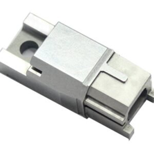
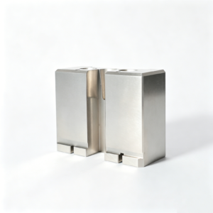
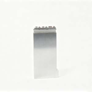
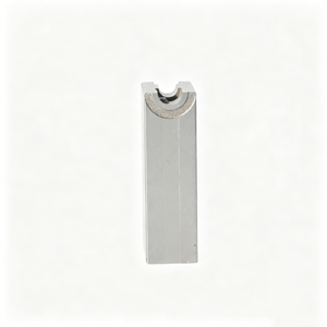
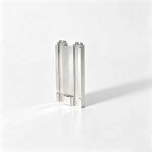
Representative Brushed-Finish Components





Related Product Catalogue and Quotation






Why Specify SUUXIANG for Brushed Finish Parts
Drawing-led controls help align cosmetic intent, functional dimensions, process routing, and inspection requirements before production begins.
Drawing-Led DFM Review
Review drawings, models, material, quantity, and application context to identify machining access, finish risks, and questions before quotation.
Datum-Aware Planning
Define critical dimensions and datum relationships early so brushing requirements do not conflict with functional interfaces, fits, or tolerance priorities.
Process Route Alignment
Coordinate CNC machining, EDM, grinding, fitting, and finishing in an appropriate sequence based on part geometry and verified project requirements.
Controlled Grain Direction
Specify the required brushed finish direction, visible faces, edge transitions, and cosmetic acceptance criteria directly on the drawing or inspection plan.
Inspection Planning
Align inspection methods, reporting needs, and acceptance priorities with the order, including surface appearance alongside applicable dimensional verification.
Revision Visibility
Keep drawing revisions, open technical questions, and delivery information visible throughout project coordination to support traceable production decisions.
Precision Parts and Tooling Families
Drawing-driven process routes for configurable components, from critical-feature machining through inspection-ready delivery.

CNC Machining Services
Precision CNC machining services for custom parts requiring defined datums, material control, critical dimensions, and inspection planning before production begins.
Upload a Drawing
CNC Milling
Custom CNC milling services for prismatic, plate, and contoured components, with tool access, fixture strategy, machining allowance, and surface requirements reviewed from the drawing.
Upload a Drawing
CNC Turning
Precision CNC turning services for shafts, sleeves, bushings, threaded features, and rotational parts where concentricity, runout, datum selection, and inspection requirements affect the process route.
Upload a Drawing
5-Axis Machining
5-axis CNC machining for complex surfaces and multi-face features where fewer setups can protect positional relationships, improve tool access, and reduce handling between operations.
Upload a Drawing
Swiss & Micro Machining
Swiss machining and micro machining for small, slender, or detail-intensive components, assessed against material behavior, feature accessibility, tolerances, and measurement practicality.
Upload a Drawing
Wire & Sinker EDM
Wire EDM and sinker EDM services for hardened materials, internal profiles, fine slots, sharp corners, and complex cavities requiring deliberate wire-path or electrode strategy.
Upload a Drawing
Precision Grinding
Precision surface and profile grinding for controlled flatness, parallelism, profile accuracy, and finishing stock after machining or heat treatment, supported by an appropriate inspection method.
Upload a Drawing
Mold Core & Cavity Inserts
Precision mold core and cavity inserts manufactured from supplied drawings and models, with attention to cavity geometry, cooling or feature access, heat-treatment sequence, finishing, and critical dimensions.
Upload a Drawing
Ejector & Ejection Components
Ejector pins, sleeves, and ejection components configured for mold function, fit, wear conditions, and mating-part relationships, with clear dimensional priorities and material requirements.
Upload a Drawing
Core Pins, Guide & Locating Components
Core pins, guide pins, and locating components produced around functional datums, fit requirements, wear surfaces, and alignment relationships with their mating mold assemblies.
Upload a Drawing
Slides, Lifters, Gates & Mold Accessories
Mold slides, lifters, gates, and accessories requiring coordinated geometry, clearance conditions, travel interfaces, and machining or EDM routes suited to the specified component function.
Upload a Drawing
Connector Mold Components
Precision connector mold components for terminal, housing, and fine-pitch tooling applications, reviewed for small-feature geometry, EDM needs, alignment, wear, and inspection access.
Upload a Drawing
Stamping Die Components
Precision stamping die components for forming, punching, guiding, and locating functions, planned around material condition, heat treatment, grinding stock, mating fits, and profile control.
Upload a Drawing
Injection, MIM, CIM & Overmolding Tooling
Injection, MIM, CIM, and overmolding tooling components produced within verified scope, with process planning informed by part geometry, molding interfaces, material requirements, and quality expectations.
Upload a Drawing
Machining Materials
CNC machining materials selected from customer specifications and application needs, with grade, condition, heat-treatment requirements, machinability, and documentation clarified before quotation.
Upload a Drawing
Surface Finishes & Heat Treatment
Surface finishing and heat treatment requirements reviewed alongside dimensional priorities, since coating buildup, distortion, hardness, and post-treatment grinding can affect final fit and inspection.
Upload a Drawing
Quality, Metrology & Documentation
Precision inspection, metrology, and quality documentation aligned to the order and verified inspection plan, covering critical dimensions, measurement methods, revision status, and required reporting.
Upload a Drawing
Prototyping & Low-Volume Production
Rapid prototyping and low-volume manufacturing for drawing-based parts and tooling components, using a process route matched to quantity, material, quality priorities, revision maturity, and target delivery date.
Upload a DrawingMaterials for a Consistent Brushed Finish

Stainless Steel
Produces a clean, directional satin appearance for housings, covers, fixtures and visible tooling surfaces. Alloy grade, grain direction and corrosion exposure should be reviewed, especially where brushed lines cross sealing faces or tight datum features.

Aluminum Alloys
Offers a light, contemporary brushed appearance for electronics enclosures, trim, brackets and machined assemblies. The softer surface can mark during handling, so specify grain orientation, edge-break requirements and whether later anodizing affects the intended appearance.

Tool Steel
Suitable for selected mold components, die elements and durable fixtures where a controlled directional texture is required. Heat-treatment sequence, hardness and grinding allowance require review because brushing after final sizing can affect critical surfaces.

Copper Alloys
Creates a warm metallic appearance for electrical contacts, thermal components and specialized tooling details. Copper and brass can respond differently to abrasion, so drawings should identify cosmetic zones, contact areas and any plating or oxidation-control requirements.

Nickel Alloys
Provides a restrained satin finish for corrosion- or heat-exposed engineering components and specialized process equipment. Material hardness and work-hardening behavior influence abrasive selection, while machined interfaces and inspection datums need masking or controlled finishing.
Brushed Finish Process Options

CNC Milling
Milling establishes profiles, pockets, faces, and datum features before finishing. Tool access, edge condition, and machining direction are reviewed so a brushed finish does not conflict with functional surfaces.

CNC Turning
Turning produces rotational diameters, bores, shoulders, and threads for cylindrical components. Surface priorities and protected dimensions should be defined before any secondary brushing or cosmetic finishing operation.

Wire EDM
Wire EDM cuts precise through-features, narrow slots, and complex profiles where conventional tool access is limited. The wire path, datum relationship, and subsequent surface treatment need coordinated drawing review.

Sinker EDM
Sinker EDM forms deep cavities, detailed internal geometry, and features requiring electrode strategy. Electrode condition, EDM allowance, and any later grinding or brushing are planned around critical dimensions.

Precision Grinding
Grinding controls flatness, parallelism, diameters, and surface condition on selected functional faces. Grinding stock and the finish boundary must be specified clearly when brushed appearance and mating performance coexist.

Controlled Brushing
Controlled brushing applies a directional texture to approved cosmetic surfaces after the required machining route. Grain direction, masking boundaries, edge preparation, and inspection samples help align the brushed finish with drawing intent.
Brushed Finish Supporting Components

Core Pins
Core pins can be supplied as drawing-defined components for mold and connector tooling. Identify functional diameters, material and heat-treatment requirements, brushed finish boundaries, and any mating or inspection-critical surfaces before review.

Guide Features
Guide and locating features help establish repeatable assembly position between tooling components. Provide datum references, fit requirements, surface-finish callouts and assembly context so machining, grinding and any brushed finish are sequenced appropriately.

Precision Inserts
Core, cavity and custom inserts can combine machined geometry with designated cosmetic surfaces. Mark protected sealing faces, EDM regions, brush direction and critical dimensions to prevent a finish requirement from affecting functional interfaces.

Slides Lifters
Slides and lifters require attention to travel surfaces, wear interfaces and assembly clearances. Define where a brushed finish is cosmetic only and where surface condition must support fitting, lubrication or controlled contact.

Gates Fasteners
Gates, fasteners and associated mold accessories can be reviewed as project-specific supporting parts. Include thread standards, material, mating conditions and identification needs to align component selection, machining route and final documentation.

Part Marking
Part numbers, revision marks and orientation identifiers can support traceability during assembly and inspection. State the marking method, location, legibility requirements and whether the marked area must remain outside the brushed finish zone.
About SUUXIANG Brushed Finish Manufacturing
SUUXIANG is the sole public-facing brand of Dongguan SuuXiang Precision Mold Co., Ltd., established in 2010 and based at Sanhe Industrial Park in Chang’an Town, Dongguan, Guangdong, China. Founded by legal representative XiaoCheng Huang, the company helps global engineering, sourcing, and quality teams turn drawings and specifications into inspected custom CNC parts, precision mold components, connector tooling, and die components.
Our work begins with drawing review, DFM, and a shared understanding of critical dimensions, datums, material, heat treatment, surface requirements, and inspection expectations. For a brushed finish, that means planning the finish direction, protected surfaces, machining allowance, and measurement method before production commitments are made.
Integrated CNC milling and turning, multi-axis machining, EDM, precision grinding, fitting, and inspection allow SUUXIANG to coordinate the process route around the part’s actual requirements. We distinguish configurable manufacturing scope from unsupported assumptions, keeping revision control, inspection planning, and delivery communication visible throughout the project.

Engineering Controls for a Consistent Brushed Finish
DFM and Datum Review
Before quotation, SUUXIANG reviews the drawing, model, critical dimensions, datum scheme, visible faces, and required grain direction. This establishes whether brushing affects fit, sealing, mating surfaces, or appearance before the manufacturing route is committed.
- Identify cosmetic and non-cosmetic surfaces
- Confirm grain direction relative to assembly
- Protect critical datums and functional interfaces
- Clarify surface and dimensional priorities

Machining and EDM Strategy
Tool access, cutter paths, EDM locations, and wire paths are considered with the final brushed finish in mind. The process route should prevent localized witness marks, difficult transitions, or texture changes that become visible after finishing.
- Plan access for visible surface continuity
- Separate EDM features from cosmetic faces where feasible
- Define edge transitions before finishing
- Review electrode and wire-EDM implications

Grinding Allowance and Preparation
A brushed finish depends on a stable prepared surface, not brushing alone. SUUXIANG evaluates machining marks, grinding stock, edge condition, and finishing sequence so the specified texture is applied after the required dimensional and surface-preparation work.
- Set grinding allowance by critical feature
- Remove machining marks before brushing
- Control deburring at visible edges
- Sequence finishing after dimensional stabilization

Inspection and Revision Control
Inspection requirements should distinguish functional dimensions from appearance criteria. SUUXIANG aligns the drawing revision, sampling expectations, inspection method, and finish acceptance notes before production, helping teams maintain traceability when changes affect both geometry and surface presentation.
- Match reports to the agreed inspection plan
- Record the applicable drawing revision
- Define acceptance criteria for cosmetic faces
- Keep delivery and revision information visible

Why Choose SUUXIANG for Brushed Finish Parts
Compare drawing review, finish definition, process planning, inspection expectations, and revision traceability before placing a precision-part RFQ.
← Swipe left or right to view →
Brushed Finish Production and Inspection Workflow
A controlled project path for drawing-based parts, with requirements, finish direction, critical dimensions, inspection evidence, and delivery coordination reviewed before each next step.
Review Drawings and Requirements
We review drawings, models, material, quantity, datums, critical dimensions, surface expectations, inspection needs, application context, revision status, and required delivery date before quoting.
Plan Process and Allowances
The team defines machining access, workholding, finish direction, EDM or grinding needs, heat-treatment sequence, brushing allowance, and inspection approach for the specified part features.
Machine Core Part Features
CNC milling, turning, multi-axis work, EDM, grinding, or fitting are selected as applicable to create functional features while protecting agreed datums and critical interfaces.
Apply Controlled Brushed Finish
Brushing is planned around the specified grain direction, visible surfaces, edge condition, and dimensional priorities, with process choices checked against the drawing and approved requirements.
Inspect Critical Part Characteristics
Inspection follows the agreed plan, confirming applicable dimensions, surface requirements, visual condition, and revision identity; requested records are prepared to match the verified order scope.
Pack and Coordinate Delivery
Finished parts are protected for shipment, identified for traceability, and coordinated against the agreed delivery plan, with project communication maintained for release and logistics details.
Start Your Brushed Finish RFQ
Provide the drawing, finish intent, and quality requirements needed for a controlled review before production commitments are made.
Upload Your Drawing Package
Send the 2D drawing and available 3D model with revision status, application context, critical dimensions, datums, and mating-part information for an informed initial review.
Define Finish Requirements
Specify material, quantity, brushed finish direction, surface expectations, heat treatment, cosmetic acceptance criteria, inspection reporting needs, and target delivery date.
Review the Process Plan
Discuss DFM findings, machining access, grinding allowance, brushing sequence, inspection approach, quotation assumptions, and any sampling or first-article requirements before release.
Approve Production Details
Confirm the agreed drawing revision, quality plan, delivery coordination, and documentation expectations so production proceeds with visible revision control and traceable communication.
Brushed Finish Certification and Quality Documentation

Customer References Published Only with Approval
Customer references are published only after written approval. Until then, SUUXIANG does not present anonymous outcomes as customer testimony.
Customer quotation and attributable outcome are pending written approval for publication. This slot will identify the relevant part family, finish direction, critical dimensions, and verified production or inspection outcome once release permission is confirmed.
Customer quotation and attributable outcome are pending written approval for publication. This slot will summarize the approved RFQ context, brushed finish specification, revision-control requirements, and measurable result supported by the project record.
Brushed Finish FAQ for Engineering Buyers
Specification, process planning, inspection, and RFQ questions for drawing-based precision parts.
How should I specify brushed finish grain direction on a CNC drawing?
Can a brushed finish affect tight tolerances or part fit?
When should heat treatment occur relative to brushed finish?
What information do you need to quote a brushed finish part?
Can you provide samples before a low-volume production order?
How should I plan lead time for brushed finish CNC components?
What inspection report can accompany brushed finish parts?
How are IP-sensitive drawings and finished parts handled for international shipment?
The Complete Buyer’s Guide to brushed finish
Use this decision framework to specify brushed finishes, compare materials and process options, evaluate capable suppliers, control cosmetic risk, and avoid drawing, inspection, pricing, and launch mistakes before production.
1. What Is a Brushed Finish?
A brushed finish is a directional satin texture produced by controlled abrasive finishing. Unlike bead blasting, which creates a more uniform matte appearance, brushing leaves a visible grain that should be defined by direction, coverage, and an approved reference where appearance is critical.
A brushed-finish note should identify visible faces, grain direction, target roughness or approved sample, edge treatment, heat-treatment sequence, and any subsequent coating. Cross-grain scratches, handling marks, and inconsistent overlap can remain conspicuous, so cosmetic acceptance criteria should be agreed alongside dimensional requirements.
2. Evolution of brushed finish
Brushed finishes are widely used where reduced glare and a controlled metallic appearance are needed on enclosures, hardware, visible fixtures, and selected precision components. In production, directional continuity, stop marks, and transitions across adjoining faces should be treated as explicit acceptance criteria rather than assumed shop practice.
Modern 2D drawings and 3D models make finish intent easier to communicate, but they do not replace a complete specification. Define visible faces, grain direction, masking boundaries, an approved comparator or sample, acceptable cosmetic defects, and inspection conditions before release.
3. Types of brushed finish
Brushed finish names are not standardized across suppliers. Define the visible grain, allowable zones, and an approved reference coupon before release.
Straight-Line Directional Brushing
Straight-line brushing runs parallel abrasive lines across a planar, accessible face. It suits plates, housings, and visible mold accessories; specify direction from a datum edge, grain continuity, and boundary limits.
Cross-Hairline Texture
Cross-hairline texture uses intersecting fine lines for a subdued, less directional appearance. It suits broad cosmetic panels; state crossing angle, line density, coverage area, and the approved visual sample.
Satin Non-Woven Brushing
Satin brushing uses non-woven abrasive media to produce a softer, diffuse sheen. It suits radiused external surfaces; specify media grade, permitted edge roll-off, and whether machining marks must be removed.
Grain Grade And Localized Patterns
Coarse grain is more visibly linear, while fine grain is quieter and shows small defects differently. For logos, stripes, or masked zones, define grit or equivalent sample, grain direction, exact extents, masking transitions, and inspection lighting.
4. brushed finish Materials and Compatibility
Five common substrate families produce noticeably different brushed finish results. Specify the alloy, grain direction, exposure environment, and any protective treatment before SUUXIANG reviews the drawing and inspection plan.
| Material | Finish Behavior | Common Use | Sourcing Caution |
|---|---|---|---|
| Stainless steel | Clean satin grain | Housings, mold hardware | Confirm grade and chloride exposure |
| Aluminum alloys | Bright, softer grain | Panels, fixtures | Specify alloy and coating need |
| Brass/copper | Warm directional sheen | Electrical details | Control tarnish protection |
| Carbon steel | Uniform industrial grain | Die components | Prevent corrosion after brushing |
| Nickel-bearing materials | Dense metallic satin | Specialty components | Confirm alloy, machining route, environment |
Material Selection Matrix
A 120–180 grit belt is a common starting convention, but the approved sample should define appearance and grain consistency.
Oxide And Protection
Aluminum forms an oxide layer; brass and copper can tarnish; carbon steel can rust. Clear coating, passivation, plating, or controlled storage may be appropriate only after environmental validation.
Stainless and nickel-bearing grades need application-specific corrosion review, especially where chlorides, cleaning chemicals, or trapped moisture are present.
5. brushed finish Customization Options
One approved sample establishes the visual target more reliably than an abrasive grade alone. Specify grain direction against drawing datums, cosmetic faces, masking limits, and acceptable edge-break appearance before release.
| Customization | Drawing Requirement | Trial Risk |
|---|---|---|
| Grain direction | Arrow tied to datum | Low |
| Abrasive appearance | Grade plus approved sample | Medium |
| Clear protection | Material and coating sequence | High |
Define The Cosmetic Zone
A drawing note should identify each brushed face, direction arrow, stop line, and non-cosmetic boundary. Require masking where grain must not enter sealing lands, bores, threads, datum surfaces, or mating features.
- State visible assembly orientation
- Dimension masking boundaries from datums
- Specify edge break before brushing
Control Marks And Sequence
Laser marks usually follow brushing when a crisp, contrasting mark is required; engraving before brushing can soften edges or collect abrasive residue. Anodizing, plating, clear coats, and conversion treatments can alter sheen, so trial panels or first-article approval are needed for appearance-critical combinations.
Lock The Lot Standard
One retained master sample, dated process note, and revision-controlled drawing create a practical cross-lot reference. Record abrasive family, direction, fixture orientation, protected areas, and inspection lighting; reapprove the finish when material, geometry, coating, or process route changes.
6. Quality Elements of brushed finish
A production-ready brushed finish is a controlled visual requirement, not merely an abrasive operation. Its acceptance depends on the specified grain, accessible geometry, inspection conditions, and handling after finishing.
Grain And Assembly Direction
One grain direction should be identified from a drawing datum or a marked view. Mating visible faces need continuous, intentional line flow; a change at a seam requires explicit approval.
A reference sample establishes acceptable grain density, sheen, and line continuity when words alone are insufficient.
Geometry And Defect Control
Tight inside corners, deep pockets, raised lettering, and narrow slots restrict abrasive access. The drawing should define whether unmatched corner texture, transition lines, or local hand finishing are acceptable.
All cosmetic zones require burr removal without rolled edges, drag marks, embedded abrasive, scratches, staining, or residual compound.
Inspection And Protection
A cosmetic-zone map should distinguish customer-visible faces from functional or concealed surfaces. Specify viewing distance, angle, lighting, reference sample, and acceptance limits for scratches, color variation, and grain breaks.
Clean gloves, interleaving film, and protected packaging prevent fingerprinting and contact damage after final inspection. SUUXIANG should align the inspection record and packing method with the approved drawing revision.
7. How to Choose a Manufacturer
Award on documented evidence, not badges. For a brushed finish, compare material-specific samples, the proposed route, inspection records, packaging controls, and response to a simulated cosmetic nonconformance.
Verify Relevant Experience
Two representative samples should match the alloy, grain direction, geometry, and viewing condition of the intended part.
One drawing review should identify tool access, protected faces, masking needs, and finish-after-machining constraints.
- Ask for sample inspection criteria.
- Ask which faces are cosmetic.
- Ask how grain direction is controlled.
Confirm Process Ownership
One route sheet should state whether brushing is performed in-house or by a qualified finishing partner.
Two evidence sets matter: traveler traceability through finishing and acceptance records for the returned lot.
- Who owns final cosmetic approval?
- How are lots identified?
- What triggers corrective action?
Test Communication And Delivery
Three pre-award questions reveal control: What is the sample plan? How are revisions frozen? How are rejects contained?
One packaging specification should prevent face-to-face abrasion, mixed lots, and grain-direction damage during shipment.
- Request DFM constraints in writing.
- Confirm capacity against the delivery date.
- Define photo-based cosmetic inspection.
8. Common brushed finish Buying Mistakes
Eight recurring RFQ omissions turn a visually simple brushed finish into rework, lot disputes, or transit damage. A written acceptance standard connects the drawing, sample, inspection method, and packaging requirement.
Define The Visual Standard
One word—brushed—does not define abrasive grade, grain spacing, sheen, or allowable marks; prototype and production lots can therefore look different. Specify a retained limit sample, viewing distance, lighting, grain direction, and acceptance boundaries.
Two photos are useful references but cannot reliably show tactile texture, color shift, or directional reflection. Approve a physical first article or coupon and record its revision with the order.
Design For Brush Access
Three defects—tool marks, EDM pits, and deep scratches—will remain visible because brushing is not corrective stock removal. Set the pre-finish surface condition and identify any permitted blend area before machining.
Four geometry risks—deep pockets, sharp internal corners, ribs, and obstructed lettering—prevent a uniform abrasive path. Review tool access during DFM, add radii or relief where possible, and define excluded surfaces.
Control Material And Delivery
Five material changes can alter grain contrast, stain behavior, and corrosion performance even when the part geometry is unchanged. Freeze alloy, heat-treatment state, and corrosion environment before sample approval.
Six packaging failures can scratch grain during handling or shipment, creating rejectable cosmetic damage. Define protective film compatibility, separators, orientation, clean handling, and pack-out inspection in the RFQ.
9. Steps to Launch a Brushed Part
A successful brushed finish launch treats appearance as a controlled requirement, not a final-shop preference. Start the RFQ with the intended visible faces, handling conditions, mating interfaces, and expected lot size.
Define The Cosmetic Zone
Step 1: Mark every customer-visible face, grain direction, masked area, and edge break on the 2D drawing. Identify exposure to fingerprints, abrasion, moisture, cleaners, or assembly contact.
Step 2: State whether connector-tooling or mold-component faces are cosmetic, functional, or both. Keep sealing, bearing, and datum surfaces outside the brushed zone unless the design specifically permits it.
Build A Reviewable RFQ
Step 3: Submit the 2D drawing, 3D model, material, heat-treatment sequence, quantity, target texture, and a retained reference sample or approved photograph. Define whether sample appearance overrides a written roughness value.
Step 4: Request DFM feedback on tool access, brushing direction across radii, EDM or grinding allowances, and finish-before-or-after machining. Resolve conflicts before prototype release.
Approve And Control Production
Step 5: Evaluate a first article under the agreed viewing conditions against the sample, grain continuity, dimensions, and critical datums. Approve the inspection method and acceptance boundaries in writing.
Step 6: Lock the process route, abrasive specification, handling, protective film, packaging orientation, and revision identifier. For repeat low-volume CNC orders, require lot traceability and review any material, process, or supplier change before release.
10. brushed finish Pricing and Cost
4 quotation variables—setup, manual brushing, masking, and inspection—usually outweigh the nominal brushing operation on low-volume precision parts. The tiers below are cost-direction indicators, not fixed SUUXIANG prices; drawings and current project evidence determine the route.
7 RFQ inputs make quotes comparable: 2D drawing and model, material/heat treatment, quantity, cosmetic faces and grain direction, brush specification or approved sample, critical dimensions, inspection report, and delivery date. Protective packaging, secondary coating, rework risk, and lot size can change both unit cost and lead time.
| Quantity tier | Part complexity | Material | Cosmetic-area coverage | Brushing specification | Finishing and inspection effect |
|---|---|---|---|---|---|
| 1–10 | Simple accessible faces | Aluminum or stainless | One exterior face | Direction only | Setup and hand labor dominate; first-article review and protective separation add time |
| 11–50 | Milled pockets or edges | Stainless steel | Two or more faces | Direction plus grit/sample | Masking, fixture changes, and grain matching increase cost risk |
| 51–200 | Moderate, repeatable geometry | Consistent approved lot | Defined cosmetic zone | Approved reference panel | Repeatable routing spreads setup; in-process visual checks remain necessary |
| 201+ | High repeatability | Material traceability specified | Limited, clearly bounded areas | Controlled grain and acceptance criteria | Batch handling lowers unit setup burden; packaging and final inspection remain quoted separately |
Ready to Review Your Brushed Finish Drawing?
Upload your drawing with material, quantity, critical dimensions, surface requirements, inspection needs, and target delivery date for a focused RFQ review.