
Precision Surface Grinding for Mold Components, Reviewed Before Machining
Upload your drawing for precision surface grinding for mold components with critical-dimension, datum, grinding-stock, and inspection planning.
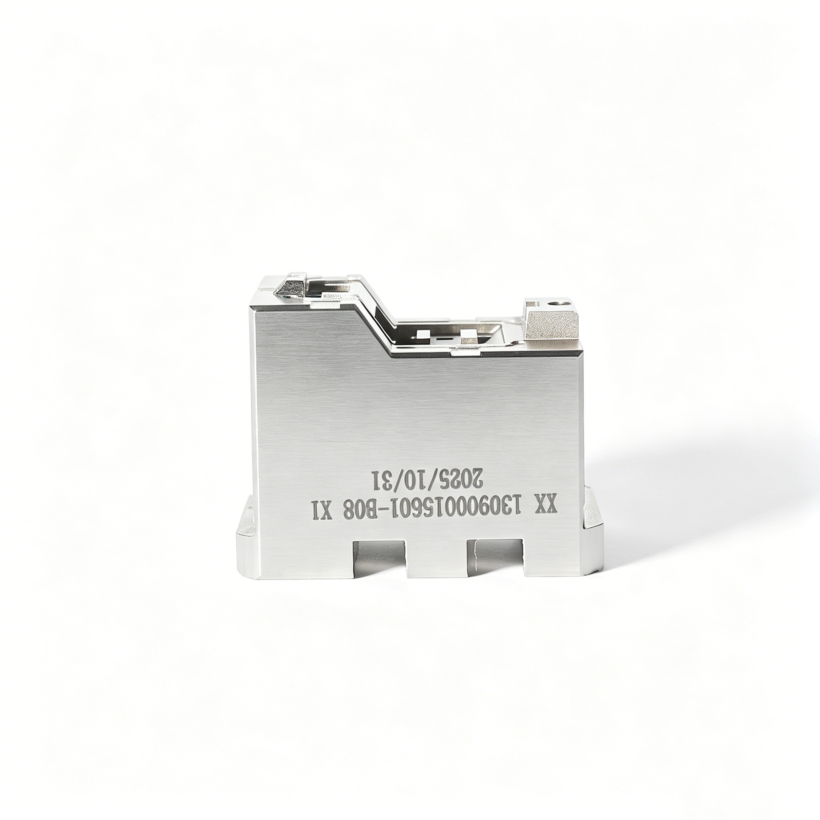
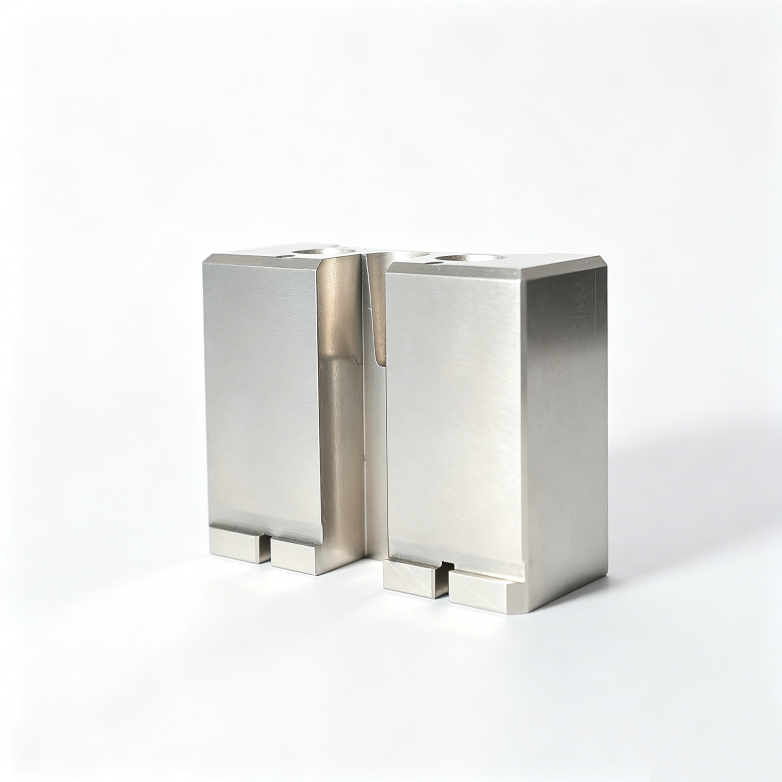
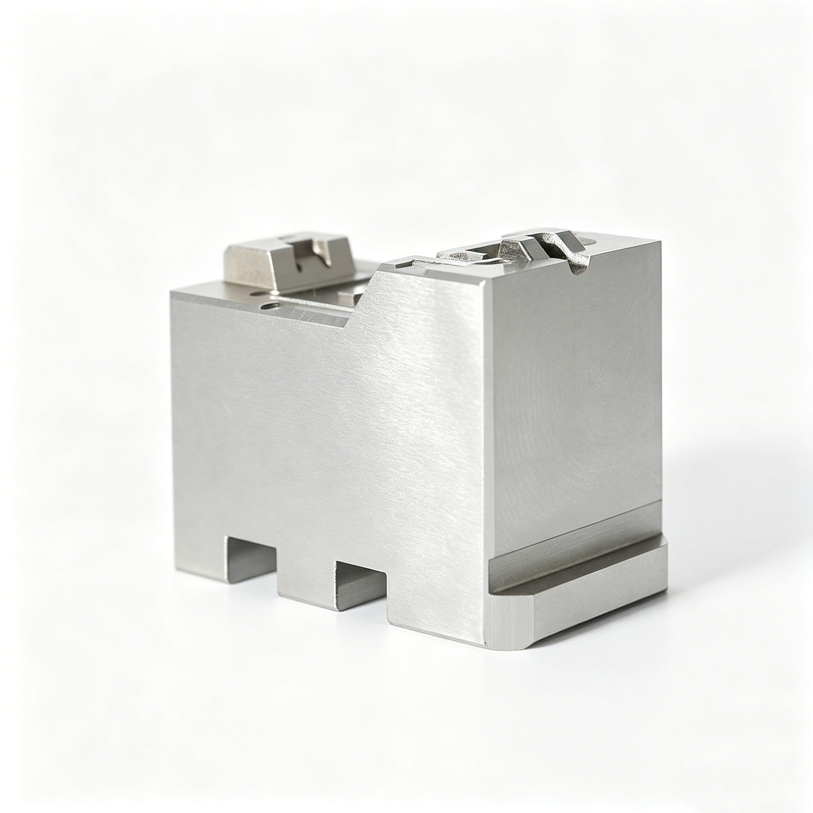
Representative Precision Mold Components for Grinding Review








Related Mold Components and Quotation


Precision Surface Grinding for Mold Components, Planned From the Drawing
SUUXIANG aligns DFM, datums, complementary processes, inspection requirements and revision communication before production commitments are made.
DFM Before Commitment
Drawing review identifies critical dimensions, grinding allowances, material conditions and access risks before quotation or production planning begins.
Datum-Aware Process Planning
Datums, tolerance relationships and functional interfaces guide setup strategy, helping align CNC, EDM and grinding operations with drawing intent.
Coordinated Manufacturing Routes
CNC machining, EDM, precision grinding and fitting are sequenced around geometry, heat-treatment condition, stock allowance and inspection needs.
Inspection Plan Alignment
Inspection methods and reporting expectations are discussed against critical features, so final documentation can match the verified order plan.
Visible Revision Control
Drawing revisions, manufacturing changes and delivery information remain visible through controlled project communication for clearer supplier coordination.
Traceable Technical Communication
Material, quantity, surface priorities and mating context can be exchanged with the RFQ, supporting a more informed production discussion.
Precision Mold Components and Machining Services
Drawing-driven process routes for custom parts, tooling components and controlled low-volume work, reviewed against critical dimensions, materials and inspection requirements.

CNC Machining Services
Precision CNC machining services begin with drawing review, material requirements and critical dimensions. CNC milling, turning and inspection are planned around geometry, tolerance stack, surface needs and the evidence required for your RFQ.
Upload a Drawing
CNC Milling
Custom CNC milling services support prismatic components, pockets, contours, plates and fixture-oriented features. Tool access, datum selection, clamping strategy and machining allowance are reviewed before committing to the proposed process route.
Upload a Drawing
CNC Turning
Precision CNC turning services suit shafts, pins, bushings, sleeves and other rotational features. The review considers concentricity, runout, thread details, datum references, material condition and any secondary grinding or EDM requirements.
Upload a Drawing
5-Axis Machining
5-axis CNC machining helps reach compound angles, complex contours and multi-face features with fewer setups where the part geometry supports it. SUUXIANG evaluates access, workholding, datum transfer and inspection strategy before production planning.
Upload a Drawing
Swiss & Micro Machining
Swiss machining and micro machining address compact rotational parts and small, detail-sensitive features. Drawing review focuses on feature scale, material behavior, tolerances, cutoff condition, deburring access and the inspection method needed to verify critical geometry.
Upload a Drawing
Wire EDM & Sinker EDM Services
Wire EDM services and sinker EDM services support hard materials, narrow slots, internal profiles, sharp-detail features and cavity geometry beyond practical cutting-tool access. Electrode strategy, wire path, EDM allowance, recast-layer considerations and finishing requirements are reviewed with the drawing.
Upload a Drawing
Precision Grinding
Precision surface and profile grinding supports controlled flatness, parallelism, profile accuracy and final-size refinement on mold and tooling components. Grinding stock, heat-treatment sequence, datum control and measurement approach must be defined before the final operation.
Upload a Drawing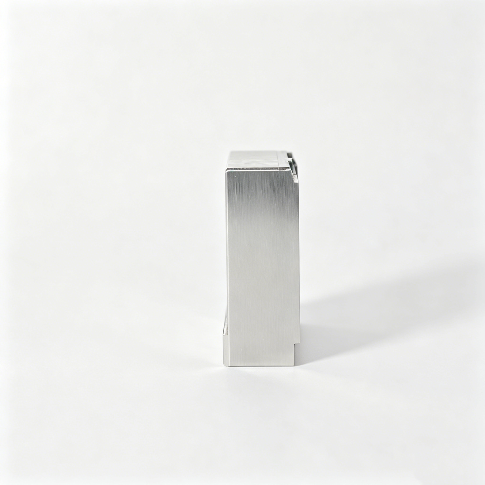
Mold Core & Cavity Inserts
Precision mold core and cavity inserts are configured from your part geometry, resin or molding context, material specification and cooling or venting requirements. Machining, EDM, grinding and fitting are coordinated around shutoff surfaces, critical details and inspection points.
Upload a Drawing
Ejector & Ejection Components
Ejector pins, sleeves and ejection components are developed from drawing-defined dimensions, sliding conditions and mold-stack interfaces. The process review addresses fit, straightness, surface condition, heat treatment, lubrication-related requirements and mating-component tolerances.
Upload a Drawing
Core Pins, Guide & Locating Components
Core pins, guide pins and locating components require disciplined control of functional diameters, seating features, alignment datums and mating fits. SUUXIANG reviews material, hardness sequence, grinding needs and inspection criteria before establishing the manufacturing route.
Upload a Drawing
Slides, Lifters, Gates & Mold Accessories
Mold slides, lifters, gates and accessories are configurable components rather than catalog assumptions. Their drawings are assessed for travel interfaces, shutoff geometry, wear areas, machining access, EDM needs, fitting requirements and the dimensions that govern mold function.
Upload a Drawing
Connector Mold Components
Precision connector mold components support fine-pitch, multi-cavity and detail-sensitive connector tooling work within verified production scope. Reviews address pin geometry, cavity relationships, datum strategy, EDM or grinding requirements, material condition and inspection accessibility.
Upload a Drawing
Stamping Die Components
Precision stamping die components are made to drawing-defined functional geometry for blanking, forming and progressive-die applications. Process planning considers tool steel condition, heat-treatment sequence, clearance-sensitive features, grinding stock, wire-EDM profiles and inspection requirements.
Upload a Drawing
Injection Mold Components, MIM, CIM & Overmolding Tooling
Injection, MIM, CIM and overmolding tooling work is evaluated as a drawing-driven manufacturing requirement, not an unlimited tooling promise. The review considers molding context, component geometry, material, shrinkage-related inputs, tool access, wear surfaces and fitting needs.
Upload a Drawing
Machining Materials
CNC machining materials are selected against the drawing, application, machinability, hardness condition and any downstream treatment. Provide the specified grade, approved alternative rules, material documentation needs and mating-part context so the proposed route can be assessed correctly.
Upload a Drawing
Surface Finishes & Heat Treatment
Surface finishing and heat treatment are planned around functional surfaces, dimensional change risk, corrosion or wear needs and inspection requirements. Specify finish callouts, hardness targets, masking needs and sequence constraints so final dimensions can be controlled appropriately.
Upload a Drawing
Quality, Metrology & Documentation
Precision inspection, metrology and quality documentation are defined around the order’s critical dimensions and agreed inspection plan. Useful RFQs identify datums, reporting expectations, sampling needs, revision status and any traceability or material-document requirements.
Upload a Drawing
Prototyping & Low-Volume Production
Rapid prototyping and low-volume manufacturing are coordinated from the current drawing revision, quantity, material and delivery requirement. SUUXIANG reviews whether the proposed process, setup approach, inspection scope and documentation level fit the requested production stage.
Upload a DrawingMaterials for Precision Surface Grinding for Mold Components

H13 Tool Steel
Often specified for mold inserts and cores exposed to thermal cycling. Drawing review should define heat-treatment condition, critical flatness, and remaining grinding stock before the machining and inspection route is confirmed.

S136 Stainless Steel
Considered for corrosion-sensitive mold components and polished cavity work. Material condition, hardness requirement, surface callouts, and EDM history should be reviewed together to establish a suitable grinding sequence.

D2 Tool Steel
Used where wear resistance is a central application requirement, including selected die and tooling components. SUUXIANG reviews section geometry, heat-treatment state, datum references, and finish expectations before confirming the process.

P20 Pre-Hardened Steel
A common option for mold bases, support elements, and certain inserts. The drawing should identify hardness condition, mating faces, parallelism priorities, and any post-machining treatment that may affect final grinding.

Tungsten Carbide
Applicable to selected wear-intensive inserts, punches, and forming details. Its material grade, geometry, bonding or mounting context, and dimensional priorities require project-specific review before grinding methods are accepted.
Grinding and Complementary Manufacturing Processes


Wire EDM
Wire EDM produces accurate through profiles, narrow slots and internal contours where cutter access is limited. Wire path, start-hole location and datum relationship are evaluated against the drawing and later fitting requirements.

Sinker EDM
Sinker EDM forms deep cavities, sharp internal details and geometry that conventional cutters cannot reach. Electrode strategy and finishing allowance are planned with the required surface condition and downstream grinding operations.

Fitting and Inspection
Fitting verifies how cores, inserts, guides and related components assemble at their functional interfaces. Inspection follows the agreed critical-dimension and datum plan, with documentation matched to the order and verified requirements.
Precision Surface Grinding for Mold Components: Assembly Features

Guide Components
Guide pins, bushes, locating blocks and alignment features can be specified for repeatable mold-half positioning. Drawing review confirms datum relationships, fit requirements, hardened surfaces and the grinding sequence needed for assembly control.

Ejection Parts
Ejector pins, sleeves, return elements and related ejection components can be produced or finished to suit the mold design. SUUXIANG reviews running clearance, bearing lengths, material condition and critical mating dimensions before machining.

Gate Features
Gate inserts, sprue interfaces and feed-related details can be configured for the required molding arrangement. The review considers tool access, EDM requirements, surface condition, replaceability and interfaces with adjacent cavity or runner components.

Slides and Lifters
Slides, lifters, wear interfaces and associated locating features can be coordinated as drawing-defined component sets. SUUXIANG evaluates travel-related clearances, datum references, grinding stock, EDM access and inspection points for practical manufacture.

Part Identification
Part numbers, revision marks and identification provisions can be incorporated where the drawing and process allow. Defined marking locations help support component recognition, assembly control and revision traceability without compromising critical functional surfaces.
About SUUXIANG Precision Manufacturing
SUUXIANG is the sole public-facing brand of Dongguan SuuXiang Precision Mold Co., Ltd., established in 2010 and based on the 2nd Floor of Sanhe Industrial Park in Chang’an Town, Dongguan, Guangdong, China. Founder and legal representative XiaoCheng Huang leads the company. We help international engineering, sourcing and quality teams convert drawings and specifications into inspected precision mold components, connector tooling and custom CNC-machined parts.
Our process planning brings CNC milling and turning, multi-axis machining, EDM, precision grinding, fitting and inspection into one controlled manufacturing workflow. For precision surface grinding for mold components, we review critical dimensions, datums, surface requirements, grinding allowance and inspection expectations before quotation or production commitments.
What distinguishes SUUXIANG is disciplined drawing review and visible revision control. Rather than treating a drawing as a simple price request, we discuss machining access, heat-treatment sequence, EDM needs, measurement methods and delivery requirements so the process route and final documentation align with the verified order.

Precision Surface Grinding for Mold Components: Core Capabilities
Critical Dimensions and Datums
Precision surface grinding for mold components begins with a drawing review that identifies functional datums, critical dimensions, flatness, parallelism, and mating relationships. SUUXIANG uses this information to clarify what must be controlled before process planning and quotation.
- Review datum references and tolerance stack requirements
- Identify surfaces governing fit, sealing, alignment, or wear
- Clarify inspection priorities before production commitments

Coordinated Process Routes
Grinding is planned alongside CNC machining, wire EDM, sinker EDM, and fitting rather than treated as an isolated finishing step. The route is selected around geometry, tool access, hardened areas, EDM requirements, and the surfaces that need final dimensional control.
- Match milling, EDM, and grinding operations to part geometry
- Consider wire paths, electrode strategy, and access limits
- Keep revision information visible across process stages

Allowance and Heat Sequence
Grinding stock and heat-treatment sequence should be reviewed before material removal begins. SUUXIANG helps teams distinguish roughing surfaces from final ground faces, so distortion risk, finish requirements, and remaining allowance can be addressed in the drawing-led manufacturing plan.
- Define grinding allowance on controlled faces
- Review heat-treatment timing against final dimensions
- Separate rough-machining and finish-grinding requirements

Inspection Plan and Records
An effective inspection plan connects drawing callouts to the appropriate measurement method and final documentation. For precision surface grinding for mold components, SUUXIANG aligns reporting needs, critical characteristics, revision status, and order requirements before final inspection is completed.
- Link critical callouts to planned inspection methods
- Confirm report and traceability requirements with the RFQ
- Match final documentation to the verified inspection plan

Precision Surface Grinding for Mold Components: Why Choose SUUXIANG
A drawing-led workflow for reviewing critical dimensions, process sequence, inspection needs, and revisions before production commitments.
← Swipe left or right to view →
Precision Surface Grinding for Mold Components: Production Process
A controlled route from RFQ review to documented delivery, aligned to the drawing, critical dimensions, process sequence, and inspection requirements.
Review RFQ and Drawings
We review 2D drawings, available 3D models, material, quantity, application, delivery target, and critical dimensions before defining quotation assumptions or production commitments.
Plan Material and Process
The team confirms datum strategy, heat-treatment sequence, machining allowance, tool access, EDM requirements, grinding stock, surface priorities, and the applicable inspection approach.
Prepare CNC and EDM
CNC machining and, where needed, wire or sinker EDM establish the part geometry while retaining planned stock for subsequent precision grinding and fitting operations.
Grind and Fit Components
Precision surface grinding brings specified faces, flatness, parallelism, and fit relationships toward final condition, with fitting coordinated against mating-component requirements where supplied.
Inspect Pack and Coordinate
Final inspection follows the agreed plan; documentation, revision status, protective packing, and delivery coordination are checked against the confirmed order requirements.
Precision Surface Grinding for Mold Components: How to Work with SUUXIANG
Move from drawing review to inspected delivery with a documented path for critical dimensions, process planning, revisions, and quality requirements.
Submit Your Drawing Package
Provide 2D drawings, 3D models when available, material, quantity, critical dimensions, surface requirements, inspection needs, application context, and target delivery date for an informed review.
Review DFM and Quotation
Review datum strategy, machining access, grinding allowance, EDM requirements, heat-treatment sequence, inspection approach, revision status, and commercial scope before production commitments are confirmed.
Confirm Production Details
Approve the agreed drawing revision, material requirements, quantity, quality documentation, delivery priorities, and sampling or production arrangement before SUUXIANG releases the work to manufacturing.
Receive Inspected Components
Receive parts produced through the agreed machining, EDM, grinding, fitting, and inspection route, with final documentation matched to the order and verified inspection plan.
Precision Surface Grinding for Mold Components: Certifications and Quality Documentation
Customer Feedback Will Be Published After Verification
Customer feedback will be published only after the project outcome, inspection documentation, and customer approval are verified.
Customer feedback is published only when the project outcome, supporting records and customer approval have been verified.
SUUXIANG does not publish unverified customer testimonials or attribute performance results to a customer without documented approval.
Precision Surface Grinding for Mold Components FAQ
Practical answers for engineering, sourcing and quality teams preparing drawing-based grinding work.
What should I include in an RFQ for precision surface grinding for mold components?
Can SUUXIANG quote precision surface grinding for mold components from a drawing only?
How do you review precision surface grinding for mold components before production?
Is there a minimum order quantity for custom ground mold parts?
How long do samples and production orders take?
What determines the price of a precision-ground mold component?
What material and heat-treatment information is needed for grinding?
Can you provide inspection reports, shipping coordination and revision control?
Precision Surface Grinding for Mold Components: Buyer’s Guide
Use this decision framework to specify flatness, finish, materials, inspection, and process routing, compare qualified suppliers, and avoid sourcing mistakes that cause fit, wear, schedule, or cost problems.
1. What Is Precision Surface Grinding for Mold Components?
Two controlled motions define precision surface grinding for mold components: an abrasive wheel removes small amounts of stock while the work is traversed to establish specified flatness, parallelism, squareness, thickness, and finish. It is normally applied to planar faces of plates, inserts, backing members, and wear components when those faces serve as datums, sealing lands, or fitting interfaces.
Three common route positions are after milling to establish stock-controlled faces, after heat treatment to correct distortion and finish hardened surfaces, and after EDM when an EDM-produced face needs a controlled reference plane. The drawing review should state the datum, geometry control, material condition, finish requirement, and measurement method, rather than only requesting ‘precision grinding.’
Four nearby operations solve different problems: polishing improves appearance or release-related texture; lapping produces exceptionally fine, closely mating faces; cylindrical grinding controls round external geometry; and hard milling creates accessible features with a cutting tool. Grinding is selected when the functional plane—not a generic process label—is the requirement.
2. Why Precision Surface Grinding for Mold Components Matters
Precision surface grinding for mold components establishes flatness, parallelism and surface condition together, helping preserve shutoff contact, cavity position and repeatable assembly rather than treating finish as cosmetic.
An uneven slide or ejector interface can concentrate load, accelerate wear and change running clearance. On cores, inserts and die details, the drawing’s datums, flatness, parallelism and roughness callouts must be interpreted against mating faces, travel direction, sealing edges and downstream polishing allowance.
Four variables set the credible result: geometry and wheel access, incoming stock condition and machining allowance, material and heat-treatment state, and the inspection method. A ground surface that looks uniform is not evidence of functional geometry; verify the specified characteristic with an appropriate datum setup and documented measurement plan before releasing it to fitting or molding.
3. Types of Precision Surface Grinding for Mold Components
Five process routes cover most drawing-based mold work, but geometry and datum requirements decide the route. Precision surface grinding for mold components should be specified with stock condition and finishing sequence.
| Route | Suitable Geometry | Strength | Limitation | Typical Application |
|---|---|---|---|---|
| Reciprocating | Flat rectangular faces | Flexible datum control | Lower area throughput | Plates, inserts, slides |
| Rotary | Circular flat faces | Productive face grinding | Limited nonround detail | Round inserts, wear pads |
| CNC/profile | External profiles | Repeatable complex contours | Wheel access constrains form | Cavity details, punches |
| Double-disc | Parallel opposing faces | High-volume thickness control | Needs stable parallel surfaces | Ejector plates, blanks |
| Creep-feed/form | Deep grooves or forms | Fewer deep passes | Higher thermal-risk control | Die forms, locator features |
Flat And Rotary Routes
Reciprocating grinding suits plates, inserts, and slide faces needing controlled flatness and parallelism. Rotary grinding favors circular faces and repeat production, but does not create internal detail.
Profile And Form Work
CNC/profile grinding follows external contours, while creep-feed or form grinding makes deep forms in fewer passes. Both require wheel-access review, dressing strategy, and heat-control planning.
Process Combinations
EDM creates inaccessible corners or narrow slots; grinding establishes datum faces afterward. Milling removes bulk stock, while lapping or polishing follows grinding only when contact, sealing, or cosmetic finish requires it.
4. Materials for Precision Surface Grinding for Mold Components
Material condition governs the process window for precision surface grinding for mold components. Grade, hardness and heat-treatment history determine abrasive choice, grinding stock, heat input and the likelihood of post-grind movement.
| Material Group | Grinding Consideration | Buyer Input |
|---|---|---|
| Pre-hardened mold steel | Wheel grade and stock removal depend on supplied hardness. | Grade and HRC |
| Hardened tool steel | Burn risk rises with aggressive heat input. | Heat-treatment sequence |
| Carbide or HSS | Abrasive choice depends on carbide content. | Exact grade and binder type |
| Nonferrous alloy | Thermal expansion can affect inspection results. | Alloy and service temperature |
Match Wheels To Material
Pre-hardened mold steel generally permits conventional aluminum-oxide wheels and moderate stock removal. Through-hardened tool steels require a sharper, cooler-cutting wheel and more conservative infeed to limit temper damage.
Carbide and high-carbide HSS commonly need diamond or CBN abrasive selected for the specific grade. Wheel supplier guidance and a trial coupon are prudent when carbide size or binder content is unspecified.
Control Heat And Stress
Heat-treated steel may retain residual stress from quenching, EDM or rough machining. Removing unequal stock from opposing faces can release stress and alter flatness after grinding.
Corrosion-resistant steels and nonferrous alloys conduct and expand heat differently from tool steel. Coolant delivery, dwell avoidance and stabilized inspection temperature therefore matter as much as the finish target.
State The Incoming Condition
An RFQ should identify the material designation, supplied hardness or target HRC, heat-treatment state and any coating. It should also show critical faces, final finish, flatness or parallelism, and stock remaining after prior machining or EDM.
- Include material certificate requirements.
- Identify stress relief or re-hardening steps.
- Flag mating, sealing and sliding surfaces.
5. Surface Finish and Functional Customization Options
Two finish callouts can describe a surface, yet its contact, sealing, sliding, or polishing role determines whether either is necessary. For precision surface grinding for mold components, specify finish with its datum and inspection method.
| Requirement | Functional Purpose | Drawing Control |
|---|---|---|
| Ground finish | General mating face | Ra and datum |
| Lapping | Critical contact | Flatness and boundary |
| Polishing preparation | Optical or texture surface | Area and stock |
| Traceability mark | Revision identification | Approved noncritical zone |
Specify Functional Finish
Ra values belong on functionally relevant faces, such as sliding or sealing interfaces; avoid a blanket cosmetic requirement. A ground finish is often the defined baseline.
One spark-out pass may improve consistency after stock removal, but it does not replace a geometry callout. State flatness, parallelism, or profile separately.
Define Prepared Features
One polishing-preparation requirement should identify the surface boundary and permitted tool access. Texture preparation likewise needs an agreed area and transition.
Two controlled details—edge breaks and reliefs—can prevent burr interference and preserve mating clearance. Define their size, location, and excluded sharp edges.
Control Matched Sets
Two matched components should use shared datums, identification, and a stated assembly condition. Inspect interface geometry as a set where function depends on it.
One traceability mark belongs on a noncritical, approved area. Exclude sealing, sliding, cosmetic, thin-wall, and datum surfaces.
6. Construction and Quality Control Elements
Critical interfaces are controlled before the first pass, not rescued by final measurement. For precision surface grinding for mold components, the drawing must define datums, acceptance limits, and reportable features.
Holding And Datum Control
Datum A should be established on a stable reference face before thickness or parallelism is ground. Magnetic holding suits adequately supported ferrous parts; thin, nonmagnetic, or interrupted parts may require mechanical clamping to prevent distortion.
Two-sided grinding must retain a documented orientation so measurements relate to the same datum scheme. Clamp pressure, support points, and stock allowance should be reviewed before setup.
Wheel, Coolant, And Stock
Wheel specification must match material condition, contact area, and finish requirement. Dressing restores wheel cutting behavior; inadequate dressing can increase heat, loading, and finish variation.
Controlled passes and consistent coolant delivery limit thermal damage and residual stress. Heat-treated parts with distortion risk may need stress-relief sequencing agreed during drawing review.
Inspection And Protection
Inspection of critical interfaces should define thickness, flatness, parallelism, squareness, surface finish and burr acceptance against the drawing. Measurement method, datum reference, sampling plan and report format should be agreed before production.
Final deburring must not roll functional edges or alter mating faces. Clean, protected parts should be packaged to prevent corrosion, contact damage and revision mix-up.
7. How to Choose a Grinding Manufacturer
A capable supplier turns the drawing into a controlled route, not merely a grinding quote. Evaluate the evidence supplied before purchase-order release for each critical mold component.
| Evaluation Area | Evidence To Request | Gap Exposed |
|---|---|---|
| DFM | Marked drawing review | Unstated datum or allowance |
| Grinding capacity | Machine envelope and setup plan | Part cannot be held safely |
| Quality | Inspection plan and calibration evidence | Unverifiable final callouts |
| Delivery | Route-based milestone plan | Quote omits approval time |
Review The DFM Response
A 2D drawing and 3D model should prompt questions on datums, grinding stock, wheel access, heat-treatment sequence, and inspection points.
A written DFM response should identify risks and proposed controls; silence on critical dimensions is a warning sign.
- Which dimensions are ground after heat treatment?
- Which datum controls the final setup?
- What stock remains after EDM or milling?
Verify Process And Measurement
Hardened tool steels require a documented route that connects machining, stress relief or heat treatment, EDM, grinding, and final inspection.
Calibrated measuring equipment must match the callout: request the method, instrument identity, calibration status, and report format.
- Confirm usable grinding envelope and workholding.
- Ask for in-process inspection checkpoints.
- Request hardness and final-dimension records when specified.
Control Matched Parts
Matched cores, cavities, slides, and guide components should be identified as sets, with mating datums and fitting responsibility agreed before manufacture.
First-article approval should define the sample quantity, acceptance record, revision status, and permitted changes before series release.
- Who owns fit verification?
- How are paired components serialized?
- What lead time includes inspection and approval?
8. Common Buyer Mistakes to Avoid
Two drawing-review failures—an absent datum and incompatible callouts—can force rework before a wheel touches the part. Resolve functional requirements, inspection evidence, and handling details in the RFQ before release.
Datums And Tolerances
One datum scheme must govern size, parallelism, and inspection. Without it, supplier and buyer may reference different faces, creating rejected but technically conforming parts.
Two conflicting requirements—such as a tight location tolerance without a stated datum—need disposition before machining. Mark functional datums and reconcile tolerances on the released drawing.
Finish And Heat Treatment
One Ra value alone is incomplete. State the measurement direction, cutoff, instrument, and measured area; otherwise finish acceptance can vary.
After heat treatment, leave agreed grinding stock and identify faces that may distort. Zero allowance or ignored movement can leave insufficient material to recover geometry.
Commercial And Delivery Controls
Three commercial controls belong in every order: process-route comparison, inspection planning, and packaging requirements. Lowest price can exclude necessary grinding, reporting, or protection.
Before purchase-order release, specify CTQ dimensions, sampling or 100% reporting, gage method, and protected ground faces. Bare contact in transit can nick sealing or sliding surfaces; require separators and labeled revision traceability.
9. From Drawing Review to First Article
A controlled launch for precision surface grinding for mold components begins before material is released. One documented sequence keeps drawing intent, process decisions, inspection evidence, and later revisions connected.
Release The Technical Package
One RFQ package should include the 2D drawing, available 3D model, revision identifier, quantity, and required date.
Two feature groups should be marked: critical-to-function dimensions and noncritical dimensions. Include datums, flatness or parallelism callouts, surface requirements, and mating-part context.
Close DFM Before Production
Four inputs require confirmation before quotation: material, heat-treatment condition, finish, and quantity.
One DFM review should resolve grinding stock, workholding access, EDM condition, datum transfer, and inspection method. Record each agreed deviation or assumption against the drawing revision.
Approve Evidence And Revisions
First-article approval should compare the part and inspection record with the released drawing and critical-feature plan.
One revision log should identify changed dimensions, material, finish, or inspection requirements before a repeat order. Reissue the controlled files rather than relying on email-only changes.
10. Precision Grinding Pricing and Cost Drivers
Three cost layers should be separated in an RFQ: non-recurring setup, per-part grinding, and inspection or expedite charges. SUUXIANG should price precision surface grinding for mold components from the controlled drawing revision, not from a nominal part category.
Two common cost multipliers are heat-treatment distortion and matched-set fitting. Warped hardened stock can require extra stock removal or rework; paired inserts, complex fixtures and added inspection reports increase total cost and may extend the schedule.
| Quantity tier | Part and process condition | Setup cost | Unit cost | Lead-time effect |
|---|---|---|---|---|
| 1–2 prototypes | Large or irregular geometry; hardened material; tight finish | High | High | Fixture, grinding strategy, and first inspection dominate |
| 3–10 pieces | Moderate size; standard geometry; defined grinding stock | Medium | Medium | Batch setup reduces handling time |
| 11–50 pieces | Repeat geometry; stable material condition; practical tolerances | Lower per batch | Lower | Repeatable fixturing supports shorter cycles |
| Any quantity, urgent | Complex datum scheme, matched set, full report, or expedited delivery | Higher | Higher | Capacity reservation and extra verification may apply |
Upload Your Drawing for Precision Surface Grinding for Mold Components
Send your 2D drawing, 3D model where available, material, quantity, critical dimensions, inspection needs, and target date for a scoped review.