
Type II Anodizing for Drawing-Based Precision Parts
Submit your drawing for Type II anodizing review, coordinated with CNC machining, EDM, grinding, and inspection requirements.
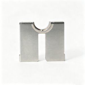
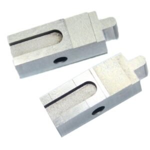
Representative Precision Components for Type II Anodizing Review





Related Configurable Component Families



Type II Anodizing, Planned From the Drawing
Turn finish requirements into a controlled manufacturing and inspection plan before production commitments are made.
Drawing-First Review
We review geometry, alloy callouts, finish notes, and mating conditions before quoting Type II anodizing for precision parts.
DFM Before Commitment
Machining access, edge breaks, thread masking, and racking considerations are identified early to reduce avoidable finishing risks.
Critical Dimensions Protected
Critical dimensions and datums are reviewed against coating buildup, tolerance stack, and functional interfaces before the process route is confirmed.
Coordinated Process Routing
CNC machining, EDM, grinding, deburring, and Type II anodizing are sequenced around material condition and feature accessibility.
Inspection Plan Alignment
Measurement methods, reporting needs, cosmetic priorities, and finish-related acceptance criteria are clarified against the drawing and order requirements.
Visible Revision Control
Drawing revisions, agreed specifications, inspection expectations, and delivery updates remain visible throughout controlled project coordination.
Type II Anodizing for Precision Components
Drawing-driven process routes for custom parts, mold components, connector tooling, and die components—reviewed against critical dimensions, material, finish, and inspection requirements.

CNC Machining Services
Precision CNC machining services for drawing-based custom parts, with process planning that considers datums, critical dimensions, machining access, material condition, and inspection requirements before production commitments are made.
Upload a Drawing
CNC Milling
Custom CNC milling services for prismatic parts, plates, inserts, and complex features. Tool access, workholding, datum sequence, remaining stock, and surface requirements are reviewed to establish a practical machining route.
Upload a Drawing
CNC Turning
Precision CNC turning services for rotational parts such as pins, sleeves, bushings, shafts, and locating features. Requirements for concentricity, runout, diameter control, threads, and mating conditions should be defined in the drawing package.
Upload a Drawing
5-Axis Machining
5-axis CNC machining supports multi-face geometries and features that benefit from fewer setups. The applicable route depends on part geometry, tool reach, datum control, surface requirements, material condition, and inspection access.
Upload a Drawing
Swiss & Micro Machining
Swiss machining and micro machining support small, detailed components where feature scale, slender geometry, and handling affect process choices. Drawings should identify critical diameters, lengths, radii, threads, burr limits, and inspection expectations.
Upload a Drawing
Wire & Sinker EDM
Wire EDM and sinker EDM services address internal profiles, narrow slots, sharp-corner requirements, hardened materials, and features with limited conventional tool access. Wire paths, electrode strategy, recast-layer considerations, and finishing requirements require early review.
Upload a Drawing
Precision Grinding
Precision surface and profile grinding supports controlled flatness, parallelism, profiles, and finishing stock on mold and die components. Grinding allowance, heat-treatment sequence, datum condition, and measurement method should be agreed before release.
Upload a Drawing
Mold Core & Cavity Inserts
Precision mold core and cavity inserts are manufactured from customer drawings and 3D models, with attention to parting geometry, shutoffs, cooling interfaces, material condition, EDM needs, grinding stock, and critical molded-part dimensions.
Upload a Drawing
Ejector & Ejection Components
Ejector pins, sleeves, and ejection components require controlled fit with the surrounding mold system. Define diameters, working lengths, head geometry, hardness or treatment requirements, surface condition, and relevant mating-component information.
Upload a Drawing
Core Pins, Guide & Locating Components
Core pins, guide pins, and locating components are planned around positional accuracy, fit, wear conditions, and mating geometry. Clear datum references, toleranced interfaces, material and heat-treatment requirements help establish the appropriate manufacturing sequence.
Upload a Drawing
Slides, Lifters, Gates & Mold Accessories
Mold slides, lifters, gates, and accessories are configurable components produced to drawing-defined interfaces and motion requirements. Review should cover travel geometry, clearances, wear surfaces, cooling or fastening features, and assembly-related critical dimensions.
Upload a Drawing
Connector Mold Components
Precision connector mold components support tooling for connector-product features where pin geometry, alignment, micro details, and repeatable mating interfaces matter. Provide the component drawing, mating context, material, treatment, and inspection priorities for DFM review.
Upload a Drawing
Stamping Die Components
Precision stamping die components include drawing-based punches, dies, guide elements, inserts, and related wear parts. Material, heat treatment, grinding and EDM requirements, working clearances, and critical profiles should be defined before process planning.
Upload a Drawing
Injection, MIM, CIM & Overmolding Tooling
Injection, MIM, CIM, and overmolding tooling work is evaluated within verified production scope. Review begins with component geometry, molding-function requirements, material condition, interfaces, critical dimensions, and the required combination of machining, EDM, grinding, fitting, and inspection.
Upload a Drawing
Machining Materials
CNC machining materials are selected against the drawing, application, machinability, dimensional stability, treatment condition, and finish requirements. Identify specified grade, supply condition, substitute restrictions, and any material certification or traceability needs in the RFQ.
Upload a Drawing
Surface Finishes & Heat Treatment
Surface finishing and heat treatment are planned as part of the dimensional route, not an afterthought. Specify the required finish or treatment, affected dimensions, masking or contact surfaces, hardness targets where applicable, and post-process inspection expectations.
Upload a Drawing
Quality, Metrology & Documentation
Precision inspection, metrology, and quality documentation are matched to the order’s verified inspection plan. Identify critical dimensions, datums, report format, sampling or full-inspection needs, material records, revision status, and traceability requirements in advance.
Upload a Drawing
Prototyping & Low-Volume Production
Rapid prototyping and low-volume manufacturing support drawing-based validation parts, tooling components, and controlled production quantities. Include quantity, material, critical features, required documentation, target date, and any application or mating-component context with the RFQ.
Upload a DrawingMaterials for Type II Anodizing Precision Parts

6061 Aluminum
A common choice for machined brackets, housings, and fixtures. Its balanced machinability and corrosion performance make it a practical Type II anodizing candidate, subject to drawing tolerances, cosmetic requirements, and finish-area review.

6063 Aluminum
Often considered for profiles, covers, and appearance-focused components. Its finish response can support decorative anodizing, while thin walls, section geometry, and visible surfaces should be assessed before machining and finishing commitment.

7075 Aluminum
Used where higher strength is important in precision structural or tooling-related parts. Machining strategy, stress condition, critical dimensions, and the specified anodized appearance require review because alloy response can vary by finish requirement.

2024 Aluminum
Selected for strength-driven applications where the drawing and operating environment justify its use. Confirm corrosion expectations, surface preparation, masking needs, and inspection priorities before committing to a Type II anodizing process route.

5052 Aluminum
Suitable for formed or sheet-derived components, covers, and lightweight assemblies. Forming history, edge condition, surface expectations, and required protection should be reviewed to align machining, preparation, and anodizing requirements.
Type II Anodizing and Supporting Process Routes


Multi-Axis Machining
Multi-axis machining supports complex contours, angled features and accessible features that benefit from fewer setups. The route is evaluated against fixture stability, cutter reach, datum transfer and the surfaces that must remain controlled after finishing.

Wire EDM
Wire EDM cuts precise profiles, narrow slots and hardened features where conventional cutter access is limited. Wire path, start-hole position, skim strategy and recast-layer requirements should be defined against functional edges and inspection datums.

Sinker EDM
Sinker EDM forms deep cavities, sharp internal geometry and difficult-to-reach details using a planned electrode strategy. Electrode wear, spark allowance, surface requirement and subsequent polishing or grinding needs are reviewed before production.

Precision Grinding
Precision grinding refines critical faces, diameters and datum relationships after appropriate machining or heat-treatment stages. Grinding stock, distortion risk, surface requirement and measurement method are considered to protect dimensional control before final finishing.

Type II Anodizing
Type II anodizing is a sulfuric-acid conversion finish for aluminum parts that can improve corrosion resistance and support clear or dyed appearances. Coating thickness, masking, dimensional effects, color expectation and inspection requirements require drawing-based review.
Type II Anodizing Component Features and Accessories

Thread Protection
Threaded holes, studs, and mating interfaces can require masking, plugs, or post-finish cleaning. Define thread class, no-coat areas, and assembly requirements during drawing review to protect fit after Type II anodizing.

Helical Thread Inserts
For aluminum parts requiring repeated assembly or stronger service threads, inserts may be evaluated after the relevant machining and finishing sequence is defined. Provide insert type, installation condition, and mating-fastener information with the RFQ.

Part Identification Marks
Laser marks, etched identifiers, revision codes, and orientation marks can support traceability and assembly control. Identify location, character size, contrast expectations, and whether marking occurs before or after Type II anodizing.

Protective Packing
Protective packing can be planned for cosmetic faces, finished edges, threads, and inspection-sensitive features. Share handling risks, pack quantity, labeling format, and destination requirements so shipment protection matches the part’s application.

Inspection Documentation
Inspection reports, dimensional records, material documentation, and finish-related requirements should align with the order and approved inspection plan. Flag critical dimensions, sampling expectations, reporting format, and revision status before production begins.
About SUUXIANG Precision Manufacturing
SUUXIANG is the sole international-facing public brand of Dongguan SuuXiang Precision Mold Co., Ltd., established in 2010 in Chang’an Town, Dongguan, Guangdong, China. Founded by XiaoCheng Huang, the company helps global engineering, sourcing, and quality teams convert drawings and specifications into inspected custom CNC parts, precision mold components, connector tooling, and die components.
Our work is drawing-driven: DFM review and critical-dimension discussion come before production planning. Depending on verified project requirements, we coordinate CNC milling and turning, multi-axis machining, EDM, precision grinding, fitting, inspection, and finishing routes such as type ii anodizing for suitable aluminum components.
What differentiates SUUXIANG is controlled technical communication. We examine datums, tolerance stack, tool access, heat-treatment sequence, surface requirements, inspection methods, and revision status so buyers can compare process routes before committing. An RFQ is stronger when it includes drawings, material, quantity, delivery targets, and quality documentation needs.

Type II Anodizing Delivery Starts With Controlled Part Planning
DFM and Datum Review
Before quotation, SUUXIANG reviews the drawing, model, datums, critical dimensions, finish callouts, and functional interfaces. For type ii anodizing parts, this discussion identifies surfaces that need masking, tolerance review, and dimensional allowance before production commitments are made.
- Confirm functional datums and critical-to-quality features
- Review finish callouts, masking needs, and mating surfaces
- Identify tool access, corner conditions, and inspection risks
- Align material, quantity, application, and delivery requirements

Process Route Planning
Each part is planned around its geometry, material condition, tolerance strategy, and finishing requirement. CNC machining, EDM, grinding, fitting, and type ii anodizing coordination are considered as one controlled route, so finishing does not become an afterthought after critical features are complete.
- Select machining, EDM, and grinding sequences by feature
- Plan stock allowance before finishing and final grinding
- Assess wire paths, electrode access, and unsupported geometry
- Coordinate finishing requirements with part handling and protection

Critical-Dimension Inspection
Inspection planning focuses on the dimensions and surfaces that determine assembly, sealing, alignment, or connector function. SUUXIANG aligns the inspection method and reporting expectation to the drawing and agreed quality plan, keeping measurement evidence connected to the delivered revision.
- Define critical dimensions and applicable measurement methods
- Check datum-based features against the approved drawing
- Align reporting needs before production begins
- Match final documentation to the verified inspection plan

Revision-Controlled Coordination
Drawing-based work depends on clear version control from review through shipment. SUUXIANG keeps revision, process, inspection, and delivery information visible during project coordination, helping teams avoid producing to superseded files or comparing results against an unapproved requirement.
- Record the approved drawing and model revision
- Clarify changes before affected operations proceed
- Keep quality expectations linked to the active revision
- Coordinate delivery information with the agreed order scope

Type II Anodizing Project Controls to Confirm
Compare the project controls that help align anodizing requirements with machining, inspection, and delivery planning.
← Swipe left or right to view →
Type II Anodizing: From Drawing Review to Shipment
A drawing-driven workflow aligns machining, finishing, inspection, and delivery requirements before production commitments are made.
Review RFQ Package
We review drawings, models, material, quantity, critical dimensions, finish callouts, inspection needs, and target delivery date to clarify the manufacturing scope.
Confirm DFM And Plan
The team assesses datums, tolerance stack, tool access, machining allowances, masking needs, and Type II anodizing requirements before confirming a practical process route.
Machine Critical Features
CNC machining, EDM, grinding, and fitting are scheduled as required to produce geometry, interfaces, and surface conditions suitable for the approved part specification.
Control Finishing Sequence
Parts are prepared for the specified finish, with handling, masking, color, sealing, and dimensional effects reviewed against drawing priorities and functional mating requirements.
Inspect Pack Coordinate
Inspection follows the agreed plan, then verified parts are protected for transit with revision, documentation, packing, and shipment coordination kept visible to the buyer.
Type II Anodizing: How to Work With SUUXIANG
Align drawings, DFM, finishing requirements, production controls, and inspection evidence before parts move into manufacturing.
Submit Your Requirements
Send 2D drawings, 3D models where available, material, finish, quantity, critical dimensions, target date, inspection needs, and mating context for an informed Type II anodizing review.
Review DFM and Quotation
Align datums, tolerance stack, machining access, anodizing mask requirements, coating callouts, and inspection method before SUUXIANG issues a controlled quotation and process route.
Approve Samples When Needed
For projects requiring validation, review first-article or sample evidence against agreed critical dimensions, surface expectations, and revision status before releasing the production lot.
Release Controlled Production
Confirm the approved revision, then coordinate CNC machining, EDM, grinding, finishing, fitting, and Type II anodizing through the documented project plan.
Receive Inspection Documentation
Receive parts with documentation aligned to the agreed inspection plan, including applicable dimensional results, revision identification, and delivery information for receiving review.
Certifications and Quality Documentation
Customer References Pending Approval
Verified customer feedback slot: publish after the customer approves a drawing-review outcome, including the revision count, inspection scope, and delivery result for a Type II anodizing project.
Verified customer feedback slot: publish after the customer approves a documented quality-coordination outcome, such as the number of critical dimensions reviewed and the agreed inspection-report requirements.
Verified customer feedback slot: publish after the customer approves a delivery-performance outcome, including quantity, revision-control details, and the agreed shipment milestone for the finished parts.
Type II Anodizing FAQ for Engineering Buyers
Practical answers for specifying anodized CNC parts, mold components, and tooling from a drawing-based RFQ.
What is type ii anodizing, and when should I specify it?
Which aluminum alloys are suitable for type ii anodizing?
How does type ii anodizing affect part dimensions and tolerances?
Should I choose Type II or Type III anodizing for a wear surface?
Can SUUXIANG provide samples before a production order?
What inspection reports can be requested for anodized parts?
How should I plan lead time, shipping, and payment for an anodized-part RFQ?
How are drawings and IP handled during a type ii anodizing inquiry?
The Complete Buyer’s Guide to type ii anodizing
Use this decision framework to specify type ii anodizing for precision aluminum parts, compare finishing suppliers, control dimensional and cosmetic risks, and avoid costly drawing, alloy, sealing, color, and inspection mistakes.
1. What Is type ii anodizing?
Type II sulfuric-acid anodizing is an electrochemical conversion finish that grows aluminum oxide (Al₂O₃) from the aluminum surface in an acid electrolyte under current; it is neither paint nor applied plating. The resulting oxide layer provides a practical balance of corrosion resistance, moderate abrasion performance, electrical insulation, and porous structure for clear or dyed finishes (https://www.xometry.com/resources/machining/sulfuric-acid-anodizing).
MIL-A-8625 commonly identifies sulfuric-acid anodizing as Type II, with standard Type II thicknesses reported at 0.00007–0.0010 in. (1.78–25.4 µm) by Xometry. That dimensional change matters on threads, bores, sealing faces, locating diameters, and tight-fitting connector or mold-tooling components.
OEM applications include electronics enclosures, architectural profiles, appliance parts, automotive components, and decorative aluminum hardware. Specify type ii anodizing for drawing-based aluminum precision parts when corrosion protection, appearance, dielectric separation, or color identification is needed, then define alloy, coating thickness, color, masking, critical dimensions, and inspection evidence in the RFQ.
2. How type ii anodizing Evolved
Aluminum forms a thin natural oxide film in air, but industrial anodizing uses an electric current in an acid electrolyte to create a more controlled oxide layer. This electrochemical route made protection, appearance, and dimensional planning more repeatable than relying on the native film alone (https://www.xometry.com/resources/machining/sulfuric-acid-anodizing).
Sulfuric-acid anodizing became the practical general-purpose route because its porous oxide can accept dyes before sealing. In the U.S. military specification family, sulfuric-acid coatings are designated Type II, with defined types and classes supporting more consistent supply-chain communication (https://alliancechemical.com/blogs/articles/sulfuric-acid-anodizing-type-ii-explained).
MIL-PRF-8625 is not a complete purchase instruction by itself. A current drawing should state the applicable standard revision, Type and class, color, required thickness, sealing requirement, masked areas, and inspection or acceptance criteria; otherwise, a generic ‘type ii anodizing’ note leaves important manufacturing and quality decisions unresolved.
3. Types of type ii anodizing
MIL-PRF-8625 terminology separates finish purpose as well as process type. Put coating type, class, thickness, seal status, color, critical dimensions, and inspection method on the drawing.
| Callout | Use | Color | Thickness Expectation | Wear And Size Impact |
|---|---|---|---|---|
| Type II, Class 1 | Clear cosmetic or corrosion finish | None | Drawing-specified | Moderate; account for oxide growth |
| Type II, Class 2 | Dyed identification or appearance | Dyed | Drawing-specified | Moderate; account for oxide growth |
| Type IIB | Lower dimensional impact | Limited | Thinner than Type II | Lower wear; reduced growth |
| Type III | Abrasion-driven feature | Usually dark | Thicker than Type II | Higher wear; greater dimensional impact |
Class And Color
Class 1 is non-dyed; Class 2 is dyed when MIL-PRF-8625 governs. Clear suits cosmetic metallic appearance or stable identification; dyed Type II needs an approved color standard.
Seal Status
Sealed Type II is the usual corrosion-focused release condition. Unsealed pores support subsequent dyeing, bonding, or controlled processing, but require an explicit downstream requirement.
Functional Alternatives
Type IIB is a thinner sulfuric-acid alternative where Type I-like dimensional impact is needed. Type III is the better callout for substantially higher wear demand; confirm allowance and final dimensions before machining.
4. Materials for type ii anodizing
6061, 6063, 5052, and 7075 are common CNC aluminum choices, but type ii anodizing is not visually interchangeable across alloys. Chemistry, temper, and starting surface determine how etching reveals the part.
| CNC Alloy | Likely Finish Behavior | Cosmetic Use | Drawing Review Question |
|---|---|---|---|
| 6061-T6 | Generally even | Good | Is clear or dyed appearance critical? |
| 6063 | Bright, smooth potential | Strong | Is extrusion texture acceptable? |
| 5052 | Variable tone possible | Moderate | What temper and grain direction? |
| 7075-T6 | Darker, less uniform | Limited | Approve a finish sample? |
| Cast aluminum | Porosity and shade variation | Poor | Is cosmetic anodizing required? |
Alloy Chemistry Matters
6061-T6 commonly produces a consistent clear or dyed technical finish; 7075 can appear darker or less uniform. Sulfuric anodizing creates oxide from the base aluminum, so qualify appearance by alloy rather than color name alone. https://www.xometry.com/resources/machining/sulfuric-acid-anodizing
Surface History Remains Visible
0.02 mm tool marks, sanding direction, or polishing variation can become more apparent after etch. Specify the pre-finish texture, machining direction, and cosmetic faces on the drawing.
Lots Need Segregation
1 mixed lot may combine wrought stock, cast stock, weld zones, or different material heats. Identify inserts and welded areas because they will not anodize like the surrounding aluminum.
5. Type II Anodizing Colors and Options
Clear, black, and custom-dyed type ii anodizing can serve functional identification or cosmetic goals. Because the oxide is translucent, it highlights alloy, machining, and texture variation rather than concealing them.
| Option | Appearance | Control Needed |
|---|---|---|
| Clear | Metallic, substrate-visible | Approved texture sample |
| Black | High contrast | Shade acceptance limit |
| Custom dye | Specified color target | Master sample and lighting |
Color And Sample Approval
Clear preserves a metallic appearance; black provides strong visual contrast; custom dyes need a defined target. Alloy, lot variation, racking, and surface preparation can shift shade.
Approved production samples should define acceptable color, gloss, texture, viewing light, and lot-to-lot variation before release.
Texture, Masking, And Sealing
Bead blasting produces a diffuse matte appearance, while brushing creates directional lines that remain visible after anodizing. Specify media, brush direction, coverage boundaries, and cosmetic faces on the drawing.
Masked areas require clear boundaries, allowable witness marks, and a reason such as electrical contact or fit control. Sealing choice should match corrosion, dye-retention, and subsequent-process requirements.
Marking Requirements
Laser marking can provide durable part numbers, revision identifiers, or assembly orientation marks. Define character height, location datum, contrast, readability method, and whether marking occurs before or after sealing.
Cosmetic logos require tighter controls than functional identification. Procurement should supply artwork, color target, approved sample, masking map, quantity, inspection expectations, and mating-part context.
6. Process Controls and Quality Elements
A controlled Type II route begins before the bath: alloy, finish, tolerances, cosmetic faces, and electrical function must be identified on the drawing or PO. The inspection plan should follow each handoff, not merely final appearance.
Material And Surface Preparation
6061, 6063, and cast alloys can etch and accept dye differently; identify alloy and temper, machining texture, and prohibited cosmetic zones before processing. Cleaning, etching, desmutting, and rinsing must be controlled because they establish the visible substrate.
0.0001–0.001 in Type II thickness is a cited general range; specify the required range and measurement locations rather than accepting a nominal-only callout. https://www.pfiinc.com/what-is-type-ii-aluminum-anodizing
Racking And Coating Control
One rack contact leaves an uncoated mark, so the drawing or PO should define allowed contact areas, orientation, and masked threads or mating faces. Sharp edges can show thinner or nonuniform coverage; deburr and state any edge-break requirement.
Approximately half of the oxide may grow above the original surface, making fits, bores, and thread limits inspection-plan decisions. Confirm whether dimensions apply before or after finish. https://www.pfiinc.com/what-is-type-ii-aluminum-anodizing
Dye, Seal, And Release
One approved color standard, lighting condition, and sample limit subjective color decisions across lots. Dyeing occurs before sealing; handling controls should protect cosmetic zones from fingerprints, abrasion, and water spotting.
MIL-PRF-8625, corrosion-test method, thickness method, electrical insulation or grounding requirement, lot identification, and certificate contents should be stated on the PO. Final records should link part revision, material lot, finish lot, inspection results, and shipment.
7. How to Choose a Type II Supplier
Two linked suppliers may touch one part: the machinist establishes dimensions, while the finisher controls the conversion coating. Evaluate the handoff as one controlled route, not two separate quotations.
Review The Drawing
Before quotation, ask how critical dimensions, datums, thread masking, racking marks, and coating buildup are reviewed. Require written feedback on alloy suitability and cosmetic-risk areas before release.
- Which dimensions apply before and after finishing?
- Which faces may show rack or contact marks?
- How will alloy variation affect color?
Confirm Evidence And Ownership
One acceptance sample should define color, gloss, visible defects, and protected cosmetic faces. Ask for coating records, inspection results, lot traceability, and a named owner for any subcontracted anodizing step.
- Is the sample retained and revision-controlled?
- Can machining and finishing lots be linked?
- Who issues corrective-action responses?
Plan Delivery And Protection
Each lead time should separate machining, finishing queue, sampling, rework allowance, and shipment. Confirm packaging prevents abrasion, mixed lots, and finish-to-finish contact after final inspection.
- What dependency can change the committed date?
- Who approves deviation or rework?
- What inspection report ships with parts?
8. Common type ii anodizing Mistakes
Three drawing omissions drive most avoidable type ii anodizing rework: undefined substrate, uncontrolled growth, and unapproved appearance. Resolve them before release, during the drawing review and inspection-plan discussion.
Name Alloy And Temper
6061-T6 and 7075-T6 can form different finishes; treating aluminum as one dyeable material can create lot-to-lot color variation. Specify alloy, temper, approved mill condition, and a representative finish sample.
Allow For Coating Growth
0.0001–0.0010 in Type II thickness is cited as a typical range (https://www.xometry.com/resources/machining/sulfuric-acid-anodizing). Final-size fits can bind when dimensions are toleranced before coating; state post-finish dimensions, coating thickness, and masked or reamed interfaces.
Control Appearance And Contact
One cosmetic face left undefined may receive a rack mark, handling witness, or color variation. Mark cosmetic zones, permitted rack-contact locations, grain direction, and acceptance lighting on the drawing.
Specify The Correct Process
Type III hardcoat is thicker and denser than Type II (https://lincolnindustries.com/blog.html/article/2022/01/01/type-ii-type-iii-anodizing-what-are-the-benefits-). Calling both hard anodize can cause the wrong wear, color, dimensional, or cost outcome; identify the required type, class, thickness, seal, and performance need.
Mask Threads And Retain Color
Mating threads and electrical lands can lose fit or conductivity if coating is applied indiscriminately. Define masking boundaries and test requirements; approve dyed color against a retained, labeled master standard with revision and lighting condition.
9. Launching an Anodized Part Program
One launch package should make the drawing, use environment, cosmetic intent, and delivery target visible before machining starts. For prototype and low-volume OEM work, treat the first build as a controlled evidence-gathering run.
Build the RFQ Package
Two files—the controlled 2D drawing and available 3D model—should accompany material, quantity, mating context, and required date. Mark critical dimensions, datums, masked areas, and customer-facing appearance zones; specify type ii anodizing, color, thickness requirement, and sealing expectation.
Close the Manufacturing Review
Before release, obtain feedback on tool access, corner radii, thread protection, machining allowance, racking locations, and alloy suitability. Resolve any dimensional change from finishing against the datum scheme, then issue one approved revision for the first-article build.
Approve and Repeat
First articles should be reviewed against the agreed inspection plan, appearance sample or color standard, and packaging method. Record the approved revision, inspection report requirements, labeling, replenishment quantity, and delivery communication path so later orders do not rely on email memory.
10. Type II Anodizing Pricing and Cost
3 quantity bands make pricing more useful than a unit-rate claim: geometry, surface preparation, racking, lot size, rework risk, and logistics change the total.
1 drawing package should state alloy, finish class, color, cosmetic zones, masking, quantity, inspection level, packaging, and required date before a comparable quote is possible.
| Quantity tier | Batch/setup burden | Masking or cosmetic complexity | Color and inspection requirements | Indicative lead-time drivers | Required quote inputs |
|---|---|---|---|---|---|
| 1–10 prototype | Highest per-part burden; fixture and rack planning spread over few pieces | Masked threads, contact faces, or visible surfaces add handling | Clear or single dye; define thickness checks and cosmetic acceptance | Drawing review, rack availability, first-piece approval, shipping | 2D/3D files, alloy, finish callout, quantity, due date |
| 11–100 low volume | Setup is shared across the lot; sorting remains material | Multiple masks or color matching increase labor and rework exposure | Define color reference, sampling plan, reports, packaging | Lot scheduling, color approval, inspection sampling | Critical dimensions, cosmetic zones, mask map, report needs |
| 101+ repeat production | Lower setup share when geometry and routing remain controlled | Stable racking and approved appearance reduce variability | Lock color standard, acceptance criteria, and audit frequency | Release forecast, batch size, repeatability, logistics lane | Revision-controlled print, forecast, release quantities, delivery terms |
Upload Your Drawing for Type II Anodizing Review
Include your 2D drawing, 3D model, material, finish, quantity, critical dimensions, inspection requirements, and target delivery date for a focused review.