
Type III Hard Anodizing for Precision Parts
Submit your drawing for a DFM review that aligns type iii hard anodizing, critical dimensions, machining allowances, and inspection requirements.
Representative Components for Hard-Anodizing Review





Related Drawing-Based Components and RFQ Support
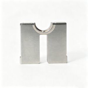

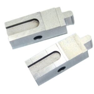


Type III Hard Anodizing Planning Advantages
Coordinate finish requirements with drawing review, critical dimensions, machining allowances, inspection evidence, and controlled revision communication.
DFM Before Release
Review alloy, geometry, masking needs, and finish callouts before quotation to identify access limits and prevent avoidable production changes.
Critical Dimension Strategy
Plan datums and coating-sensitive dimensions early, accounting for machining stock and functional interfaces before type iii hard anodizing is released.
Coordinated Process Route
Align CNC machining, EDM, grinding, deburring, and finishing sequence with the drawing so each operation supports the intended final condition.
Inspection Plan Alignment
Define critical features, measurement methods, reporting expectations, and acceptance criteria against the order-specific inspection plan before production begins.
Revision Visibility
Keep drawing revisions, clarified requirements, and delivery coordination visible throughout the project to reduce ambiguity between engineering and sourcing teams.
Traceable Communication
Connect technical questions, agreed decisions, and final documentation to the applicable drawing and inspection requirements for clearer supplier-quality review.
CNC Machining and Precision Tooling Families
Classify drawing-driven component needs, then align process route, critical dimensions, material condition, inspection requirements, and delivery expectations before quotation.

CNC Machining Services
Precision CNC machining services for custom parts and tooling components produced from controlled drawings and models. Process planning considers material, critical dimensions, datum scheme, tool access, surface requirements, inspection method, quantity, and revision status before production is committed.
Upload a Drawing
CNC Milling
Custom CNC milling services support prismatic and contoured components requiring pockets, bores, features, and controlled datums. Drawing review identifies clamping strategy, tool reach, corner-radius limitations, machining allowance, surface priorities, and inspection points appropriate to the part.
Upload a Drawing
CNC Turning
Precision CNC turning services are suited to rotational parts such as pins, sleeves, bushings, shafts, and threaded features. Review concentricity, runout, diameters, shoulder geometry, material condition, finishing requirements, and mating relationships before defining the machining and inspection route.
Upload a Drawing
5-Axis Machining
5-axis CNC machining supports complex faces, angled features, and multi-sided geometry where fewer setups can protect positional relationships. Feasibility depends on tool access, clamping, feature depth, material, tolerance requirements, and an inspection strategy tied to functional datums.
Upload a Drawing
Swiss & Micro Machining
Swiss machining and micro machining address small, slender, or detail-dense turned parts where support, concentricity, and feature access require careful planning. Submit dimensions, material, quantity, surface requirements, critical features, and mating-component context for process review.
Upload a Drawing
Wire & Sinker EDM
Wire EDM and sinker EDM services support hardened materials, fine internal geometry, sharp-profile requirements, and features inaccessible by conventional cutting. Electrode design, wire path, flushing, recast-layer considerations, finishing passes, and datum references should be established from the drawing.
Upload a Drawing
Precision Grinding
Precision surface and profile grinding supports flatness, parallelism, profile control, and fine dimensional adjustment after machining or heat treatment. Define grinding stock, hardness condition, datum sequence, surface requirement, critical dimensions, and the inspection method required for acceptance.
Upload a Drawing
Mold Core & Cavity Inserts
Precision mold core and cavity inserts are configurable drawing-based components for injection-tool applications. Review steel selection, heat-treatment sequence, parting-line geometry, cooling or feature access, EDM requirements, grinding allowance, critical cavity dimensions, and fitting relationships before manufacture.
Upload a Drawing
Ejector & Ejection Components
Ejector pins, sleeves, and ejection components are produced to drawing requirements for guidance, clearance, wear behavior, and repeatable mold operation. Provide diameters, lengths, hardness or finish requirements, mating bores, datum references, quantity, and any critical running-clearance expectations.
Upload a Drawing
Core Pins, Guide & Locating Components
Core pins, guide pins, and locating components require controlled geometry where alignment, wear, and mating fit affect tooling performance. Drawing review should cover material and heat treatment, concentricity, locating surfaces, lead-in details, grinding needs, fit class, and inspection priorities.
Upload a Drawing
Slides, Lifters, Gates & Mold Accessories
Mold slides, lifters, gates, and accessories are custom tooling components rather than stocked configurations. Their review considers travel or interface geometry, wear surfaces, material condition, lubrication or clearance requirements, EDM and grinding needs, fitting sequence, and relationships with adjacent mold parts.
Upload a Drawing
Connector Mold Components
Precision connector mold components support tooling for detailed connector features, often with small pitches, delicate pins, and demanding alignment conditions. Include the component drawing, mating-part context, critical dimensions, material and hardness requirements, surface condition, inspection needs, and revision level.
Upload a Drawing
Stamping Die Components
Precision stamping die components include drawing-defined punches, inserts, guide elements, forming features, and related wear components. Process planning should account for tool steel condition, heat treatment, wire or sinker EDM needs, grinding stock, edge condition, mating clearance, and inspection criteria.
Upload a Drawing
Injection, MIM, CIM & Overmolding Tooling
Injection, MIM, CIM, and overmolding tooling components are evaluated within verified production scope. Provide the tooling drawing, molded-material or application context, critical interfaces, shrinkage or alignment considerations, material and heat-treatment requirements, surface needs, quantity, and documentation expectations.
Upload a Drawing
Machining Materials
CNC machining materials are selected against functional requirements such as strength, corrosion behavior, machinability, heat-treatment response, wear, and dimensional stability. Identify the required grade or approved equivalent, material condition, traceability needs, application environment, and any restrictions before quotation.
Upload a Drawing
Surface Finishes & Heat Treatment
Surface finishing and heat treatment must be specified with the functional purpose and sequence in mind. Clarify required finish, roughness, coating or treatment type, hardness range where applicable, masking or critical surfaces, post-treatment grinding allowance, dimensional priorities, and verification requirements.
Upload a Drawing
Quality, Metrology & Documentation
Precision inspection, metrology, and quality documentation are planned around the order’s critical dimensions and agreed acceptance criteria. Identify datums, tolerances, sampling expectations, measurement method preferences, report format, traceability requirements, revision control, and any customer-specific quality documentation.
Upload a Drawing
Prototyping & Low-Volume Production
Rapid prototyping and low-volume manufacturing support drawing-driven validation parts, tooling components, and controlled small-batch requirements. An effective RFQ includes the 2D drawing and model where available, material, quantity, critical features, inspection needs, target delivery date, and revision status.
Upload a DrawingAluminum Materials for Type III Hard Anodizing

6061 Aluminum
A widely specified machinable aluminum alloy for housings, fixtures, and structural parts. Review temper, critical dimensions, sealing needs, and masking before type iii hard anodizing, because oxide buildup and final appearance must be controlled against drawing requirements.

7075 Aluminum
A high-strength aluminum option often considered for loaded precision components. Confirm the specified temper, machining condition, feature geometry, and intended service environment during DFM review so the proposed finish supports functional surfaces and inspection priorities.

2024 Aluminum
An aluminum alloy used where drawing requirements may prioritize mechanical performance. Review corrosion expectations, material condition, contact surfaces, and post-finish documentation with the complete application context before committing to a production process route.

6063 Aluminum
An aluminum alloy commonly associated with profiles and formed shapes. For precision-machined features, verify wall thickness, exposed cosmetic surfaces, masking boundaries, and final dimensional requirements before selecting machining allowances and a hard-anodizing approach.

5052 Aluminum Sheet
A sheet-based aluminum option for formed or lower-profile components. Evaluate forming history, edge conditions, surface texture, mating areas, and coating growth against the drawing before defining the final finish and inspection method.

Cast Aluminum Alloys
Cast aluminum grades require drawing-specific review of alloy identity, porosity risk, machined surfaces, and cosmetic expectations. Confirm which areas require functional finishing and which dimensions need post-process verification before production planning begins.
Supporting Machining and Finishing Processes


Wire EDM
Wire EDM supports intricate profiles, narrow slots, and hardened features where conventional cutting access is limited. The wire path, corner condition, and post-process surface requirement should be defined before the finishing sequence is released.

Sinker EDM
Sinker EDM forms deep cavities, sharp internal details, and complex mold features using controlled electrode strategy. Electrode allowance, recast-layer management, and subsequent polishing or grinding requirements are evaluated against drawing-critical surfaces.

Precision Grinding
Precision grinding controls flatness, parallelism, diameter, and surface finish on functional faces. Grinding stock and final dimensions require careful planning when a coating or surface treatment may affect fit, sealing, or mating-part clearance.

Fitting Inspection
Fitting and inspection confirm critical interfaces, datum relationships, and assembly-sensitive features before shipment or finishing coordination. The inspection method, reporting format, revision status, and acceptance criteria are aligned with the approved drawing.

Finishing Coordination
Finishing coordination connects part preparation, masking instructions, coating requirements, and post-finish inspection. SUUXIANG reviews the requested route with the project evidence so dimensional priorities and surface expectations remain visible through delivery.
Type III Hard Anodizing Specification Controls

Masking Areas
Identify surfaces that must remain uncoated, including electrical contacts, bonding zones, press fits, and sealing lands. Define masking boundaries and permitted edge transition locations directly on the drawing.

Thread Protection
Call out internal and external threads requiring protection, post-process cleaning, or controlled allowance. Thread class, engagement depth, and mating requirements should be reviewed before type iii hard anodizing is specified.

Datum Surfaces
Mark datum faces and locating features used for manufacture and inspection. This lets the team distinguish cosmetic surfaces from functional references and plan measurement after machining and finishing.


Mating Interfaces
Flag bores, sliding faces, interference fits, sealing interfaces, and assembled-component clearances. Discuss dimensional change, contact conditions, and inspection method early to avoid a finish that compromises assembly function.
Type III Hard Anodizing, Drawing-Driven
SUUXIANG is the international-facing brand of Dongguan SuuXiang Precision Mold Co., Ltd. Established in 2010 and based in Chang’an Town, Dongguan City, Guangdong, China, the company was founded by and is legally represented by XiaoCheng Huang. We help global engineering and sourcing teams turn drawings, models, and specifications into inspected CNC-machined parts, precision mold components, connector tooling, and die components.
For parts requiring type iii hard anodizing, the finish must be considered before machining is committed. Our team reviews critical dimensions, datum strategy, surface requirements, masking needs, machining access, and inspection expectations so the drawing, process route, and finishing specification can be aligned before quotation and production.
What differentiates SUUXIANG is disciplined coordination across CNC machining, EDM, grinding, fitting, and inspection. We communicate revision status and project requirements clearly, helping buyers evaluate manufacturing risks and supply the material, quantity, quality, delivery, and reporting details needed for a responsible RFQ.

Type III Hard Anodizing: From DFM to Inspection
Review Critical Dimensions
SUUXIANG begins with the drawing, 3D model, alloy, coating callout, and functional requirements. The review identifies dimensions affected by type iii hard anodizing, datum relationships, masking needs, thread requirements, and surfaces where post-finish growth or fit must be controlled.
- Identify critical-to-quality dimensions and functional datums
- Confirm coating callout, finish zones, and masking requirements
- Review threads, bores, mating faces, and tolerance stack risks
- Align material, quantity, application, and delivery requirements

Plan Machining and EDM Access
Before production, machining routes should preserve access to features that require CNC milling, turning, wire EDM, or sinker EDM. Tool approach, electrode strategy, wire path, corner condition, and pre-finish surface requirements are reviewed against the drawing rather than assumed from a generic process.
- Check cutter access and minimum internal-feature geometry
- Define EDM features that cannot be machined conventionally
- Review electrode and wire-path implications for precision details
- Protect surfaces whose condition affects final function

Control Grinding and Fitting
Grinding and fitting decisions require a clear sequence around heat treatment and finishing. SUUXIANG reviews grinding stock, contact surfaces, assembly relationships, and allowable material removal so the selected route supports the intended fit without treating a coating specification as an isolated finishing step.
- Assign grinding allowance before downstream operations
- Identify fitted interfaces and controlled contact surfaces
- Review heat-treatment sequence with dimensional priorities
- Document any required post-process fitting checks

Align Inspection Documentation
Inspection planning connects the purchase order to the actual critical features and finish expectations. For type iii hard anodizing projects, SUUXIANG aligns measurement methods, sampling or reporting needs, revision status, and delivery documentation before production commitments, subject to the evidence required for the order.
- Match inspection methods to critical dimensions and datums
- Confirm coating-related verification and reporting expectations
- Maintain visible drawing revision and order traceability
- Coordinate final records with the approved inspection plan

Why Choose SUUXIANG for Type III Hard Anodizing Parts
Compare the engineering controls that help align machining, finishing, inspection, and revision requirements before production.
← Swipe left or right to view →
Type III Hard Anodizing Production Workflow
A drawing-driven path from technical review through finishing coordination, inspection, packing, and delivery documentation.
RFQ and Drawing Intake
Share 2D drawings, 3D models, material, quantity, functional surfaces, and delivery targets. SUUXIANG records revision context and identifies information needed for responsible review.
Critical Dimension Review
Engineers assess datums, tolerance stack, tool access, coating-sensitive dimensions, threads, bores, and masking needs before confirming a practical manufacturing and finishing route.
Process Route Planning
The team defines CNC, EDM, grinding, heat-treatment, and type iii hard anodizing coordination, including machining allowance, finishing sequence, and inspection checkpoints.
Machining and Finish Coordination
Parts proceed through approved machining operations while critical surfaces and revision status remain controlled. Finishing requirements are coordinated against the drawing and agreed process plan.
Inspection Against Requirements
Fitting and inspection confirm critical interfaces, datum relationships, and assembly-sensitive features before shipment. The inspection method, reporting format, revision status, and acceptance criteria are aligned with the approved drawing and inspection plan.
Pack and Release Documentation
SUUXIANG prepares order-matched packing and delivery documentation, maintaining traceability to the approved revision, inspection expectations, quantity, and agreed shipment information.
Start Your Type III Hard Anodizing Review
Provide the technical inputs needed to evaluate machining, finishing, inspection, and delivery requirements before quotation.
Send Your Drawing Package
Upload the 2D drawing and available 3D model, identifying revision status, critical dimensions, datums, surface requirements, and any mating-part context that affects function.
Define Material and Finish
Specify the aluminum alloy, Type III hard anodizing requirement, masking areas, coating expectations, and any heat treatment or pre-finish condition relevant to the design.
Set Quality Priorities
State quantity, inspection or reporting needs, dimensional priorities, cosmetic acceptance criteria, and traceability expectations so the review can align process planning with risk.
Confirm Delivery Requirements
Share the target delivery date, shipping considerations, and program context. SUUXIANG reviews manufacturability, process route, and inspection needs before preparing a controlled quotation.
Quality Evidence and Documentation
Type III Hard Anodizing Customer Project Feedback
Verified customer feedback for drawing review, inspection reporting, and delivery coordination will be published here when SUUXIANG has approval to share the project outcome and supporting details.
This space is reserved for an approved customer account of how revision control, critical-dimension communication, and inspection documentation supported a Type III hard anodizing project.
SUUXIANG will add verified project feedback here only after the customer approves publication of the application context, measurable outcome, and relevant delivery or quality evidence.
Type III Hard Anodizing FAQ for B2B Buyers
Practical questions to resolve before quotation, machining, finishing, inspection, and delivery planning.
Which aluminum alloys should be reviewed for Type III hard anodizing?
How much dimensional allowance is needed for type iii hard anodizing?
Can threads, bores, or contact areas be masked during type iii hard anodizing?
Do I need a sample before ordering hard-anodized CNC parts?
What inspection requirements should I provide for type iii hard anodizing?
How does type iii hard anodizing affect lead time?
Can SUUXIANG ship type iii hard anodized parts internationally?
How are IP-sensitive drawings handled for an anodizing RFQ?
Complete Buyer’s Guide to type iii hard anodizing
Use this decision framework to specify type iii hard anodizing, compare supplier capabilities, control tolerances and finish risk, evaluate inspection evidence, and avoid costly design, quoting, and production mistakes.
1. What Is type iii hard anodizing?
MIL-A-8625 Type III is commonly used to describe hard anodizing, also called hardcoat or hard anodize. It is an electrochemical conversion process in which aluminum at the surface is converted into aluminum oxide while the part acts as the anode, rather than receiving a separate deposited layer.
The drawing must define the required coating range and dimensional allowance. The oxide is integral with the aluminum substrate and may be selected for abrasion and wear resistance, corrosion resistance, or dielectric isolation. Confirm the applicable specification, test requirements, and acceptance criteria for the project.
Before specifying this finish, assess whether its dimensional change, alloy response, and mating-surface consequences suit the actual design need.
2. Evolution of type iii hard anodizing
Type I, Type II, and Type III classifications separated chromic-acid, sulfuric-acid, and hard anodic coatings as users needed different corrosion, dye-base, and wear outcomes. Industrial mechanisms, aerospace hardware, tooling, and precision components pushed demand toward thicker, denser oxide where sliding, abrasion, or dielectric isolation mattered. https://www.balseal.com/wp-content/uploads/2019/03/effects_of_hard_anodizing_aluminum_alloys_on_bal_sealTR_17.pdf
MIL-A-8625 Type III gave buyers common language for hard anodic coatings; related drawing language may also reference current military, AMS, customer, or aerospace specifications. A specification name alone is incomplete: alloy, coating class, thickness range, sealing condition, color, masked areas, and acceptance method determine the practical requirement.
25 µm is a useful example of why modern callouts require dimensional planning: coating growth changes fits, threads, bores, and datum-controlled features. During supplier qualification, submit the drawing and mating context, then confirm the applicable revision, process route, thickness measurement locations, inspection record, and any required test evidence before production.
3. Types of type iii hard anodizing
MIL-A-8625 distinguishes Class 1, undyed coatings, from Class 2, dyed coatings. Treat those classes as appearance and identification choices; separately specify seal state, thickness, and any secondary film.
Class 1 And Class 2
Class 1 is natural or undyed; alloy, thickness, and process conditions can still produce gray, bronze, or dark shades. Class 2 adds dye, so approve a representative color standard rather than naming a color alone.
Coating thickness, color uniformity, and dye uptake vary by alloy and geometry. Define the required thickness range, inspect at agreed locations, and visually assess cosmetic surfaces against agreed acceptance criteria.
Sealed Or Unsealed
Unsealed hardcoat retains open pore structure, which can support subsequent paint, adhesive, or lubricant systems. Specify it when adhesion or impregnation is functional, then protect handling surfaces from contamination.
Sealed hardcoat reduces pore access and is generally selected where corrosion exposure or cleanability governs. State the seal method when performance depends on it, and define corrosion or seal-quality testing with the finisher.
Hardcoat And Secondary Films
Conventional sulfuric Type III hardcoat is the base process; it is selected primarily for wear resistance and dielectric behavior. A dry-film lubricant, PTFE system, or other topcoat changes friction, appearance, thickness, and inspection needs.
One finish callout should name the governing specification, Class, coating thickness range, seal status, color, masked areas, and required tests. Require cross-hatch adhesion or friction testing only when the application defines acceptance criteria.
4. Aluminum Alloys for Hard Anodizing
6xxx, 5xxx, 2xxx, and 7xxx aluminum do not hard-anodize alike. For type iii hard anodizing, alloy chemistry and temper set realistic expectations for growth, shade, corrosion response, and dimensional change.
| Material family | Suitable use | Finish risk |
|---|---|---|
| 5xxx/6xxx wrought | Machined brackets, housings | Shade variation; confirm cosmetic need |
| 2xxx wrought | Strength-driven components | Copper can reduce color consistency |
| 7xxx wrought | High-strength parts | Zinc-related shade and corrosion review |
| Silicon-rich cast | Noncosmetic cast geometry | Dark, nonuniform appearance; porosity |
Alloying Elements Matter
Silicon-rich alloys can give darker, less uniform oxide and are common in castings. Copper-rich 2xxx and zinc-rich 7xxx alloys can shift color and require corrosion-performance review.
Magnesium-bearing 5xxx and 6xxx grades are often selected where a more consistent functional finish is needed. Final shade still depends on alloy lot, geometry, racking, and process control.
Cast Versus Wrought
Cast aluminum often contains more silicon and porosity than wrought stock, increasing cosmetic variation risk. Wrought bar or plate generally provides more predictable machining and coating appearance.
Thin ribs, blind pockets, and sharp internal corners can make current distribution and coating build less uniform. Disclose machined-from-solid versus casting before quotation.
RFQ Disclosure
2D drawings should identify alloy, temper, critical dimensions, coating condition, and cosmetic zones. 3D models should show mating surfaces, masking requirements, and areas where coating growth affects fit.
5. Type III Hard Anodizing Options
Type III hard anodizing options should be specified as functional requirements first, then appearance requirements. Alloy, surface preparation, thickness, and fixturing can change the resulting shade.
| Request | Primary Purpose | Drawing Or Control-Plan Definition |
|---|---|---|
| Natural finish | Functional baseline | Alloy, texture, acceptable shade range |
| Black or ID color | Cosmetic or sorting | Approved sample and lighting condition |
| Seal or secondary coating | Functional protection | System, zones, cure, verification |
| Laser mark | Traceability | Location, content, contrast, depth limit |
Color And Identification
Natural hardcoat may range from gray to dark olive or brown; it is not a controlled cosmetic color. Black dye and identification colors are conditional options, but require approved limit samples.
Color is primarily cosmetic unless visual sorting prevents assembly errors. Define alloy, texture, dye, lighting, and acceptable variation on the control plan.
Masking And Rack Marks
Masked threads, bores, electrical contacts, and fit surfaces must be dimensioned on the drawing. Identify selective-finish boundaries and allowed masking bleed.
Rack marks are unavoidable contact locations. State permitted location, maximum area, and any forbidden sealing or mating zone.
Sealing And Secondary Steps
Sealed coatings prioritize corrosion resistance, while unsealed pores may support subsequent paint, lubricant, or adhesive systems. Confirm compatibility using the actual coating supplier and application.
Laser marking after finishing can provide traceable identification. Define content, position, contrast, depth limit, and inspection acceptance criteria.
6. Critical Quality and DFM Elements
Type III hard anodizing changes both functional dimensions and inspection risk. For drawing-based CNC and tooling parts, define what is coated, what is masked, and how acceptance will be measured before release.
Dimensions And Edge Preparation
Type III oxide grows partly above and partly into the original surface; allocate fit tolerances after the required coating thickness is agreed. Specify finished dimensions for bores, bearing lands, slides, and mating features.
Sharp edges can show thin coverage or become fragile. Add a controlled edge break or radius where the functional design permits, and identify no-coat sealing faces.
Masking And Surface Requirements
Threads, precision bores, electrical contacts, and datum pads need explicit masking or post-finish sizing instructions. Identify each masked area on the drawing, including allowable rack-contact location.
Ra requirements should be stated before finishing because coating can alter measured texture. Require the specified alloy and temper by material certificate; alloy variation can change color and coating response.
Inspection And Acceptance Records
100% visual inspection criteria should define permitted rack marks, color variation, burns, pits, and handling damage. Agree the lighting, viewing distance, and cosmetic zones rather than accepting an undefined ‘uniform’ appearance.
Lot-level records should link parts, base material, finish lot, revision, and inspection method. Request coating-thickness measurements at agreed locations, masking confirmation, and any adhesion test required by the applicable specification.
- Thickness locations and measured values
- Material and finish-lot traceability
- Revision-controlled inspection report
7. Choosing a Type III Manufacturer
One supplier review should trace the part from drawing release through final inspection. A quotation that only names type iii hard anodizing does not establish control of post-finish dimensions, masked interfaces, or revision history.
Verify The Engineering Review
Two drawing checks matter before release: identify functional datums and calculate coating growth on bores, threads, fits, and sealing faces. Ask for DFM feedback covering machining allowance, racking points, masking boundaries, and final measurement sequence.
Audit Process Control
Three linked controls distinguish a managed program: material traceability, a defined anodizing process window, and qualified in-house capability or an approved finishing partner. Request first-article sampling criteria, lot identification, and the action taken when thickness or appearance falls outside the agreed requirement.
Confirm Inspection And Response
Four records should follow the order: revision-controlled drawing, inspection plan, dimensional results, and nonconformance disposition. Confirm the supplier can measure critical features after finishing and communicate corrective actions, containment, and resampling before shipment.
8. Common Buyer Mistakes
Type III is not a complete release specification. Seven recurring omissions turn an otherwise workable hardcoat requirement into fit, appearance, electrical-contact, or acceptance disputes.
Incomplete Finish Callouts
Type III without target thickness, class, seal condition, and test requirement leaves the finisher to choose the functional result. Ask: What thickness range, Class 1 or Class 2, sealing state, and acceptance standard apply to each surface?
Unplanned Dimensional Change
Hardcoat changes finished dimensions, especially on bores, threads, sliding fits, and datum-controlled interfaces. Ask: Which dimensions apply before versus after anodizing, and what machining allowance or mask boundary is required?
Alloy And Color Assumptions
Aluminum alloy and prior surface condition affect coating growth, shade, and cosmetic consistency; vague names such as black do not define a limit. Ask: Is the alloy, preparation, color reference, permitted variation, and rack-mark location approved?
Undefined Protected Areas
Masked electrical contacts, press fits, threads, and mating surfaces need drawing-defined boundaries before routing. Ask: Which zones must remain bare, what masking method is acceptable, and are edge transitions functionally critical?
Sample Approval Without Limits
First-article approval without measurable limits can approve appearance while leaving thickness, dimensions, and defects subjective. Ask: Which gauges, sample size, inspection records, color criteria, and reject limits govern release?
9. Launching a Hard-Anodized Part
One controlled launch begins with an RFQ containing the 2D drawing, 3D model when available, quantity, mating conditions, and service environment. SUUXIANG uses that package to align the process route, finish intent, and inspection evidence before release.
Freeze The Technical Package
One release package identifies the aluminum alloy, type iii hard anodizing callout, target thickness, sealing requirement, and cosmetic acceptance. Critical dimensions, datums, masked electrical contacts, threads, and bearing surfaces must be marked before machining.
- State prototype, low-volume, or ramp quantity
- Identify sliding, sealing, and mating interfaces
- Attach revision-controlled drawings and models
Review DFM And First Article
One DFM review checks tool access, racking locations, coating buildup allowance, and post-finish measurement access. A prototype or connector-tooling part should proceed through first-article approval; color samples require a defined comparison method and lighting condition.
Lock Production Controls
One approved first article becomes the reference for repeat production, with defined gauges, sampling, finish checks, and required records. Mold components and ramped programs need revision control: changes to alloy, geometry, masking, or finish acceptance trigger renewed review.
10. Type III Hard Anodizing Cost
1 project-specific quotation starts with the controlled drawing, alloy, coating thickness, masked areas, quantity, and inspection requirements. Cost cannot be responsibly estimated before SUUXIANG reviews geometry, datums, tolerances, and the finish sequence.
2 or more finish variants on one order can create separate masking, handling, verification, and scheduling steps. Consolidate compatible thickness, color, sealing, and reporting requirements where function permits; quote exceptions separately.
| Quantity tier | Primary cost drivers | Finish and inspection scope | Typical lead-time effect |
|---|---|---|---|
| Prototype / low volume | Small parts may still require dedicated setup; deep bores, pockets, and rack access add handling. | Specify alloy, thickness, masking, dye or seal, and report format. | Setup and routing dominate. |
| Repeat batch | Part size, surface area, geometry, and alloy response affect processing effort. | Use one approved finish callout when practical. | Scheduling becomes more efficient. |
| Mixed requirements | Multiple thicknesses, colors, seals, or masking zones require segregation. | Critical dimensions may require added pre- and post-finish checks. | Extra coordination can extend routing. |
| High inspection level | Tight datum-related dimensions and traceability require a defined inspection plan. | Identify sampling, records, and acceptance criteria in the RFQ. | Documentation review may add time. |
Start Your Type III Hard Anodizing Drawing Review
Send your drawing, material, quantity, quality requirements, delivery target, and application context so SUUXIANG can assess DFM and inspection needs.