
Vibratory Tumbling for Precision Parts
Send your drawing for vibratory tumbling review, process planning, and inspection requirements aligned to your component’s critical dimensions.
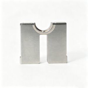
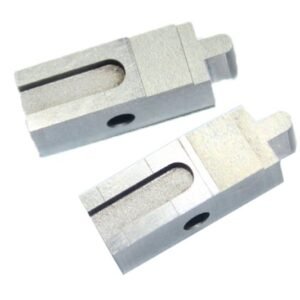
Representative Precision Parts for Vibratory Tumbling Review





Drawing-Based Components Suitable for Vibratory Tumbling



Why SUUXIANG for Vibratory Tumbling Projects
A drawing-first workflow for aligning finishing requirements with manufacturability, critical dimensions, inspection needs, and revision control.
Drawing-First Review
Each vibratory tumbling RFQ begins with a drawing review to identify functional requirements, tolerances, surfaces, quantities, and application context before planning.
Practical DFM Input
DFM discussion considers datum strategy, tool access, edge conditions, and finishing sequence so manufacturing choices support the part’s intended function.
Critical Dimension Focus
Critical dimensions are separated from cosmetic targets, helping align machining, EDM, grinding, and vibratory finishing considerations with measurable acceptance criteria.
Inspection Planning
An inspection plan can define relevant methods, reporting needs, and traceability expectations before production, keeping evidence aligned with the approved drawing.
Revision Visibility
Visible revision control helps prevent outdated files or assumptions from reaching production, supporting clearer coordination when drawings, requirements, or delivery priorities change.
Precision Component Families We Support
Drawing-driven process routes for configurable parts and tooling components, reviewed against critical dimensions, material requirements, inspection needs, and delivery priorities.

CNC Machining Services
Precision CNC machining services for drawing-based custom machined parts requiring coordinated milling, turning, EDM, grinding, fitting, and inspection. RFQ review should identify critical dimensions, datums, material condition, surface requirements, quantity, and documentation expectations before a process route is committed.
Upload a Drawing
CNC Milling
Custom CNC milling services support prismatic components, plates, inserts, pockets, contours, and feature-rich mold or die details. Drawing review considers tool access, clamping strategy, internal-corner limitations, datum sequence, machining allowance, and features that may require EDM or grinding.
Upload a Drawing
CNC Turning
Precision CNC turning services support rotational parts such as pins, shafts, bushings, sleeves, collars, and threaded features. A practical review evaluates diameter tolerances, concentricity, runout, shoulder access, workholding, material condition, and whether secondary milling, grinding, or inspection steps are needed.
Upload a Drawing
5-Axis Machining
5-axis CNC machining supports complex surfaces and multi-face features where fewer setups can help protect datum relationships. Process planning evaluates tool reach, collision clearance, part restraint, surface finish direction, tolerance stack, and the appropriate balance between machining and EDM.
Upload a Drawing
Swiss & Micro Machining
Swiss machining and micro machining support small-diameter, detail-intensive parts such as miniature pins, sleeves, connector features, and precision shafts. Feasibility depends on material, feature geometry, slenderness, tolerances, surface requirements, quantity, and inspection method.
Upload a Drawing
Wire & Sinker EDM
Wire EDM services and sinker EDM services address hardened materials, narrow slots, sharp internal profiles, fine details, and features with limited cutting-tool access. Planning considers wire path or electrode strategy, flushing, corner requirements, recast-layer expectations, stock allowance, and finishing operations.
Upload a Drawing
Precision Grinding
Precision surface and profile grinding supports tight flatness, parallelism, profile, and surface requirements on hardened inserts, plates, pins, and die components. Drawings should define critical datums, grinding stock, heat-treatment sequence, measurable tolerances, and the required inspection approach.
Upload a Drawing
Mold Core Inserts & Mold Cavity Inserts
Precision mold core and cavity inserts are configured from the part geometry, resin or molding application, gate strategy, cooling requirements, material condition, and critical cosmetic or dimensional surfaces. Reviews address machining access, EDM details, heat treatment, fitting interfaces, and inspection points.
Upload a Drawing
Ejector & Ejection Components
Ejector pins, sleeves, and ejection components are reviewed for fit, guidance, wear surfaces, clearance, stroke conditions, material requirements, and mating-part relationships. Drawing packages should identify critical diameters, hardness or treatment needs, surface requirements, and any assembly-specific inspection criteria.
Upload a Drawing
Core Pins, Guide & Locating Components
Core pins, guide pins, and locating components require controlled relationships between functional diameters, reference datums, mating holes, and installation features. Manufacturing planning evaluates slenderness, heat-treatment sequence, grinding needs, wear conditions, tolerances, and measurement methods appropriate to the application.
Upload a Drawing
Slides, Lifters, Gates & Mold Accessories
Mold slides, lifters, gates, and accessories are produced as configurable tooling components with attention to travel, clearance, parting-line interfaces, wear surfaces, and assembly fit. Effective RFQs include mating geometry, material and treatment requirements, critical dimensions, and revision-controlled drawings.
Upload a Drawing
Connector Mold Components
Precision connector mold components support fine-pitch, alignment-sensitive tooling features used in connector production. Reviews focus on cavity and core geometry, pin or insert relationships, micro-feature access, EDM strategy, grinding requirements, material condition, and inspection evidence for critical functional dimensions.
Upload a Drawing
Stamping Die Components
Precision stamping die components include drawing-based punches, dies, inserts, guide elements, and wear components. Process selection considers material grade, hardness, edge geometry, clearance relationships, grinding stock, wire-EDM path, surface condition, and how critical dimensions will be verified.
Upload a Drawing
Injection, MIM, CIM & Overmolding Tooling
Injection mold components and tooling for MIM, CIM, and overmolding are assessed within verified production scope for component geometry, material, and quality requirements. Reviews consider molding interfaces, shrinkage assumptions provided by the customer, insert fit, gate features, surface requirements, and maintenance-sensitive details.
Upload a Drawing
Machining Materials
CNC machining materials are selected against functional loading, corrosion exposure, wear, machinability, heat treatment, and inspection requirements. Specify material standard, condition, substitutions policy, certification needs, and any mating-material context so the process route can be evaluated accurately.
Upload a Drawing
Surface Finishes & Heat Treatment
Surface finishing and heat treatment are planned around function rather than specified generically. Requirements should identify hardness range, treated depth where relevant, coating or finish type, masking needs, dimensional effects, post-treatment grinding allowance, cosmetic priorities, and documentation requirements.
Upload a Drawing
Quality, Metrology & Documentation
Precision inspection, metrology, and quality documentation are defined from the drawing’s critical-to-quality features and agreed inspection plan. Discuss datums, measurement methods, sampling or full inspection needs, report format, material or treatment records, revision control, and traceability required for the order.
Upload a Drawing
Prototyping & Low-Volume Production
Rapid prototyping and low-volume manufacturing support drawing-driven validation, bridge requirements, and controlled replenishment when the scope is suitable. Quote review should clarify quantity, material, critical features, revision maturity, inspection level, target delivery date, and whether process adjustments are acceptable between stages.
Upload a DrawingVibratory Tumbling Materials Considered During Drawing Review

Tool Steels
Tool steels used for mold cores, inserts, pins, and die components require review of hardness, grinding allowance, edge condition, and corrosion protection. Vibratory tumbling may support deburring or surface refinement when critical features are protected.

Stainless Steels
Stainless steel components need material-grade, passivation, burr-control, and surface-finish requirements defined together. For connector tooling and precision parts, vibratory tumbling media and compound selection must avoid unwanted edge change, contamination, or finish inconsistency.

Carbon Alloy Steels
Carbon and alloy steels are common in structural, fixture, stamping-die, and custom machined parts. Heat-treatment sequence, scale removal needs, and post-finishing corrosion control influence whether vibratory tumbling is appropriate before final inspection or coating.

Aluminum Alloys
Aluminum alloys require controlled media contact because soft surfaces can mark or embed debris. Drawing review should identify alloy, temper, anodizing requirements, cosmetic surfaces, and dimensional priorities before proposing vibratory tumbling or an alternate finishing route.

Copper Alloys
Brass, copper, and related alloys are often specified for conductive connector components and precision fittings. Their softer surfaces and plating-sensitive areas require careful media selection, burr assessment, and defined cleaning expectations to preserve mating and cosmetic requirements.
Vibratory Tumbling Process Routes

CNC Milling Turning
CNC milling and turning establish the primary form, datums, and functional features of custom parts. Tool access, stock condition, and critical dimensions are reviewed before selecting a machining sequence and finishing allowance.


Wire EDM Cutting
Wire EDM is considered for precise profiles, narrow slots, and hardened-material features where conventional cutter access is limited. Wire path, start-hole needs, corner conditions, and remaining stock are reviewed against the drawing.

Sinker EDM Forming
Sinker EDM forms detailed cavities, deep ribs, and internal geometry using a planned electrode strategy. Electrode wear, spark gaps, surface requirements, and downstream polishing or grinding allowances are evaluated before production.

Precision Grinding
Precision grinding refines critical surfaces after machining or heat treatment when controlled stock removal is required. The process plan considers datum stability, grinding allowance, surface requirement, geometry, and the specified inspection method.

Fitting Inspection
Fitting and inspection verify functional relationships, critical dimensions, and drawing-defined requirements before release. Inspection planning is aligned with the order, selected datums, revision level, and any reporting or traceability expectations provided with the RFQ.
Vibratory Tumbling Component Details

Guide Features
Guide pins, bushings, locating faces, and alignment features can be reviewed against mating conditions, datum references, and edge-break requirements so finishing does not compromise fit or functional location.

Ejector Elements
Ejector pins, sleeves, return elements, and related mold details require clear diameter, hardness, surface, and movement requirements. Drawing notes help define where vibratory tumbling is appropriate and where controlled protection is needed.

Gate Details
Gate areas, runner interfaces, and small transition features should identify permitted edge condition, surface priority, and protected dimensions. This supports process planning without treating a functional mold feature as a standard add-on.

Part Markings
Laser marks, identification codes, orientation marks, or revision labels should be defined by location, legibility, depth, and timing. Include marking requirements in the drawing package to coordinate them with the specified finishing route.

Inspection Notes
Critical dimensions, datum strategy, cosmetic zones, and reporting requirements guide inspection planning. Identify features that must remain protected during vibratory tumbling so the inspection method matches the finished-part acceptance criteria.
About SUUXIANG Precision Manufacturing
SUUXIANG is the sole public-facing brand of Dongguan SuuXiang Precision Mold Co., Ltd., established in 2010 and based at the 2nd Floor of Sanhe Industrial Park, Chang’an Town, Dongguan City, Guangdong, China. Founder and legal representative XiaoCheng Huang leads the company. We help international engineering, sourcing, and quality teams convert drawings and specifications into inspected custom CNC parts, precision mold components, connector tooling, and stamping-die components.
Our manufacturing workflow combines CNC milling and turning, multi-axis machining, EDM, precision grinding, fitting, and inspection. For vibratory tumbling and other secondary finishing requirements, the drawing review identifies surface priorities, critical dimensions, datum relationships, edge conditions, and the evidence needed before production planning proceeds.
What differentiates SUUXIANG is disciplined project control from DFM through final inspection. We review manufacturability, machining access, process sequence, inspection methods, revisions, and delivery requirements against the actual order rather than treating every request as a standard catalog part.

Engineering Vibratory Tumbling Quotes
DFM Before Process Selection
Each vibratory tumbling inquiry starts with the drawing, model, material, application, and finish expectation. SUUXIANG reviews part geometry and critical features before proposing a route that may combine machining, EDM, grinding, and secondary finishing.
- Identify critical dimensions, datums, and surface priorities
- Review access constraints, thin sections, and vulnerable edges
- Clarify whether finishing can affect fit or cosmetic requirements
- Align the proposed route with quantity and delivery needs

EDM and Grinding Allowance
Fine finishing cannot replace a controlled machining plan. Where a part requires wire EDM, sinker EDM, or precision grinding, SUUXIANG evaluates stock allowance, heat-treatment sequence, electrode strategy, and final surfaces so vibratory tumbling is applied at an appropriate stage.
- Define grinding stock before final-size operations
- Review wire paths and electrode access for detailed features
- Assess heat-treatment sequence against distortion risk
- Separate functional surfaces from finish-sensitive areas

Inspection Linked to Requirements
Inspection planning follows the approved drawing and revision, rather than a generic checklist. SUUXIANG helps establish which dimensions, surface conditions, and documentation need verification, enabling traceable communication from drawing review through final inspection and delivery coordination.
- Match inspection points to critical-to-quality features
- Confirm measurement method and reporting expectations
- Keep drawing revisions visible during production coordination
- Request required material, heat-treatment, and inspection records early

Vibratory Tumbling Quotes: Engineering Review vs. Generic Handling
Compare the information and controls that help move drawing-based precision parts toward a defined manufacturing and inspection plan.
← Swipe left or right to view →
Vibratory Tumbling: Drawing-to-Inspection Process
A controlled workflow for drawing-based precision parts, from DFM review through finishing, inspection, packing and shipment coordination.
Review RFQ Package
We review drawings, 3D models, material, quantity, application context, delivery target and reporting needs to identify missing information before quotation.
Confirm DFM Priorities
Critical dimensions, datums, surface requirements, machining access, heat-treatment sequence, vibratory tumbling suitability and inspection methods are aligned before production commitments.
Plan Process Route
The team defines the appropriate CNC machining, EDM, grinding, fitting and finishing sequence, including allowances and handling considerations for critical part features.
Machine Critical Features
Production follows the approved drawing revision, applying the planned machining, EDM and grinding operations while maintaining visible project coordination and revision control.
Finish And Inspect
Parts receive the specified fitting or finishing steps, then are checked against the agreed inspection plan with documentation matched to order requirements.
Pack And Coordinate Shipment
Accepted parts are prepared for packing and shipment coordination, with delivery information communicated against the confirmed project requirements and available logistics details.
How to Start a Vibratory Tumbling Project
Align drawing requirements, finishing expectations, production information, and delivery documentation before work begins.
Submit Your Drawing Package
Send 2D drawings, 3D models when available, material, quantity, critical dimensions, surface priorities, delivery target, and inspection or reporting requirements.
Review Process and Quote
Align DFM findings, vibratory tumbling objectives, machining allowances, access risks, sampling needs, quality checkpoints, revision status, and quotation assumptions before commitment.
Approve Production Information
Confirm the controlled drawing revision, material and heat-treatment requirements, finishing acceptance criteria, inspection method, documentation needs, and agreed project schedule.
Coordinate Inspection and Delivery
SUUXIANG coordinates production updates, final inspection against the agreed plan, order-matched documentation, packing requirements, and delivery information for your receiving process.
Quality Documentation for Vibratory Tumbling Orders
Customer Outcomes Are Published Only When Verified
SUUXIANG publishes customer outcomes only when project evidence and publication permission are verified. Submit a drawing to discuss an applicable process route and inspection plan.
Case examples are published only after the drawing requirements, finishing route, inspection evidence, outcome, and customer permission have been verified.
For an applicable review, submit the drawing, material, quantity, critical dimensions, surface requirements, and inspection expectations.
Vibratory Tumbling FAQ for Engineering RFQs
Practical questions to resolve before SUUXIANG reviews a drawing, finishing requirement, and inspection plan.
What information is needed for a vibratory tumbling RFQ?
Can vibratory tumbling be used on precision CNC and mold components?
Will vibratory tumbling change my part tolerances?
Is there a minimum order quantity for vibratory tumbling parts?
Can I request a sample before production?
How should I plan lead time for CNC machining and vibratory tumbling?
Can SUUXIANG provide inspection reports with an order?
How are shipping, payment, and IP protection handled for custom parts?
Complete Buyer’s Guide to vibratory tumbling
Use this decision framework to specify vibratory tumbling for drawing-ready parts, compare process and supplier criteria, control finish risk, and avoid costly mistakes in media selection, inspection, quoting, and production launch.
1. What Is vibratory tumbling?
A vibratory finishing vessel uses controlled vibration to circulate parts with shaped media and, in wet processing, water and compound. The resulting media-to-part contact can deburr edges, smooth surfaces, remove light residues, burnish, or create a more uniform pre-finish condition.
Two production questions determine fit: can the component tolerate controlled edge conditioning, and will media reach without damaging critical features? Precision CNC parts, mold inserts, stamping-die components, and connector-tooling components may suit the process when datums, sealing lands, sharp functional edges, threads, delicate pins, and cosmetic faces are protected or excluded.
A 0.01 mm tolerance should never be assumed to survive a finishing cycle without part-specific validation. Vibratory tumbling is a surface-finishing operation, not a substitute for CNC machining, wire EDM, grinding, or other dimensional processes that establish geometry, location, and final critical tolerances.
2. Evolution of vibratory tumbling
Manual filing, abrasive stones, and hand deburring were the baseline for small production lots, but results depended heavily on operator pressure, access, and repeated handling. Rotary barrels later mechanized batch abrasion by continuously rolling parts and media, which suited robust parts but could round edges and increase contact damage risk.
Vibratory finishing changed the motion from barrel rotation to controlled oscillation of a workpiece-media mass. Industry references note that this action can reach internal features such as holes while the load moves together, reducing the need to manipulate each part during the cycle (https://en.wikipedia.org/wiki/Vibratory_finishing).
Modern drawing-controlled sourcing treats vibratory tumbling as a defined secondary operation, not an automatic finishing step. The RFQ should identify burr condition, protected datums and threads, allowable edge break, target surface condition, media exclusion needs, and inspection criteria so the batch route can be trialed and documented against the part drawing.
3. Types of vibratory tumbling systems
Five system categories cover most sourcing decisions: choose the vessel around part geometry, loading volume, required finish, and the ability to keep parts separated. Wet operation carries fines and heat away; dry operation suits selected burnishing or drying steps but requires dust control.
| Configuration | Best Fit | Handling And Separation | Key Risk |
|---|---|---|---|
| Bowl | Small, robust batches | Screen or discharge separator | Nested parts |
| Tub | Large or long batches | Manual unload or screen | Part-to-part contact |
| Trough | Long, delicate components | Compartments or fixtures | Bending thin sections |
| Continuous-flow | High, repeatable volume | Automated feed and separation | Unproven residence time |
| Centrifugal-style | Compact parts needing faster action | Batch unload and screening | Thread and edge damage |
Batch Vessels
Bowl systems suit small, robust parts in repeatable batches and can use unload doors or media-part screens. Tub and trough machines provide easier manual loading for longer or larger components.
Thin walls, sharp threads, and nested geometries need compartmenting, fixtures, or a trial load. Do not assume a screen will separate parts that can wedge in media.
Production Flow Choices
Continuous-flow systems suit stable, higher-volume work when feed rate, residence time, and downstream separation are validated. Centrifugal-style finishing gives higher energy for compact parts, but can raise collision, edge-rounding, and media-entrapment risk.
Wet compounds are normally selected for cleaning and debris removal; dry media can support polishing or drying. Match the route to an approved surface specification, not appearance alone.
4. vibratory tumbling media and compounds
Media choice determines how quickly a burr is cut, how much edge radius is created, and whether small features remain protected. Match it to alloy, burr root, surface target, and the cleaning route after finishing.
| Media | Cutting And Finish | Shape Or Risk |
|---|---|---|
| Ceramic | High cut; matte to refined | Angles can lodge in small features |
| Plastic | Moderate, gentler refinement | Cones reduce part-on-part contact |
| Steel | Low cut; bright burnish | Heavy; may peen fragile edges |
| Organic | Light polish or drying | Fine granules can remain in recesses |
| Specialty | Application-specific action | Verify compatibility and removal |
Match Media To Features
Ceramic cuts aggressively and suits robust burrs; plastic is gentler for softer alloys and controlled cosmetic refinement. Steel burnishes, while walnut shell or corn cob supports drying or light brightening rather than heavy cutting.
Small triangles, wedges, and spheres reach different areas, but media must be larger than holes, slots, or thin gaps that could trap it. Test sharp sealing edges and fine pins first; hard media can chip delicate edges.
Control Compound Carryover
Waterborne compounds can clean oils, lubricate contact, suspend fines, and provide temporary corrosion control. Their concentration and rinse sequence must be validated against the alloy and any later plating, welding, bonding, or assembly.
Final residues matter on connector and mold components: specify rinse quality, drying method, and allowed inhibitor film in the RFQ. Source reference: https://www.iqsdirectory.com/articles/deburring-equipment/vibratory-tumbler.html
5. Surface specifications and process customization
Two documents should define the finish: the drawing and a written acceptance standard. Specify the functional result before selecting vibratory tumbling parameters.
| Requirement | Drawing Or Standard Must State | Process Consideration |
|---|---|---|
| Deburr | Maximum residual burr and edge break | Media cut and cycle time |
| Cosmetic face | Allowed marks and protected faces | Separation and media selection |
| Plating preparation | Cleanliness and masking areas | Chemistry, rinse, and handling |
Define The Required Result
A drawing note should state burr-removal limits, edge-break size or radius, target roughness, and permitted cosmetic variation. Name the inspection area and the unacceptable conditions, such as rolled edges, media lodging, scratches, or stain.
Protect Functional Surfaces
Critical faces, datums, threads, sharp sealing lands, and mating features require explicit protection instructions. Identify masking, plugs, fixturing, no-contact zones, and the cleanliness level required after separation and washing.
Qualify The Process Window
Five variables—media, chemistry, cycle time, load ratio, and part separation—can be adjusted to reach a defined outcome. They cannot compensate for an ambiguous drawing, missing sample, or undefined acceptance criterion.
6. Quality controls in vibratory tumbling
For drawing-critical parts, vibratory tumbling requires a controlled, documented route rather than a visual pass/fail judgment. Lot identity, media condition, chemistry, cycle parameters, and inspection criteria should remain linked to the revision-controlled work order.
Part Separation And Protection
Small media must not lodge in cross-holes, threads, slots, or connector features. Screen selection, compartmented bowls, fixtures, or protected loading should prevent part-to-part contact and preserve cosmetic faces.
Critical edges require defined masking or a no-process zone when even a small edge break affects sealing, fit, or datum function.
Repeatable Process Windows
Each approved batch should record media type and wear state, part load, compound concentration, water flow, cycle time, and machine setting. A first-off sample establishes the acceptable result before the remaining lot is released.
Changed media, chemistry, or part geometry requires review because the original process window may no longer protect dimensions.
Cleanliness And Final Verification
Rinse and dry steps must remove abrasive fines and compound residues from holes, threads, and recessed features. Prompt drying and suitable temporary corrosion protection are necessary where material and downstream storage warrant them.
Inspection should combine magnified burr checks with dimensional verification of fits, radii, and critical datums. Inspectors should also check for embedded media, scratches, residue, and unintended edge rounding.
7. Choosing a vibratory tumbling supplier
A capable supplier turns a drawing, part sample, and acceptance criteria into a controlled finishing route. Ask for evidence of comparable material, geometry, and surface-risk experience before treating vibratory tumbling as a routine outsource step.
| Evaluation Area | Capability Question | Evidence To Request |
|---|---|---|
| Comparable parts | Has this material and geometry been finished? | Sample review and prior-route discussion |
| Process control | Can the route be repeated? | Recorded media, chemistry, and cycle parameters |
| Quality release | How is acceptance confirmed? | Inspection plan and lot-linked results |
| Delivery protection | How are surfaces preserved? | Packaging proposal and traceability label |
Start With Engineering Review
One review should identify datums, burr-sensitive edges, holes that may retain media, cosmetic faces, and prohibited contact areas. A sample part or representative coupon makes those risks testable before production.
- Provide 2D drawing and 3D model
- State material, hardness, and coating status
- Mark critical dimensions and appearance zones
Request A Controlled Route
One documented route should name the pre-cleaning condition, media type and size, compound, water condition, cycle target, separation method, and drying step. Revision-controlled records let buyers compare trial and production conditions.
Validate The Trial Lot
A small trial lot should be inspected against agreed edge, surface, cleanliness, and dimensional criteria. Packaging should prevent part-to-part damage, retain lot identity, and preserve the approved condition through transit.
- Ask who approves deviations
- Ask how media and chemistry changes are recorded
- Ask which inspection method verifies acceptance
8. Common vibratory tumbling mistakes
Vibratory tumbling is a controlled finishing operation, not a cosmetic afterthought. A drawing, RFQ, and inspection plan should define what may change—and what must remain protected.
Define Functional Finish
1. Calling for ‘deburr and polish’ alone can round functional edges or alter surface behavior. Specify permitted edge break, roughness target, measurement location, and excluded surfaces.
2. Omitting media-entrapment review leaves holes, slots, and blind features contaminated or damaged. Identify minimum openings, masked cavities, and required post-process cleaning.
Control Material And Corrosion
3. Mixing dissimilar metals in one load can cause cross-contamination, staining, or galvanic corrosion after wet processing. Require segregated loads, compatible compound, rinse, drying, and preservation steps.
4. Wet-process residues can corrode carbon steel during transit or storage. State corrosion-protection method, packaging condition, and visual acceptance criteria in the inspection plan.
Validate The Production Route
5. Accepting an unvalidated sample can hide part-to-part variation, dimensional change, or finish loss at production scale. Approve a representative sample with documented media, cycle, cleaning, and inspection results.
6. Exposing datums, sealing lands, threads, or precision fits risks assembly failure. Mark protected interfaces on the drawing and require masking, separate handling, and final dimensional verification.
9. Launching a controlled finishing program
A controlled vibratory tumbling launch begins before parts enter the bowl. Engineering, quality, and procurement should approve one measurable finish definition, one representative sample route, and one revision-controlled record.
Define The Finish
Step 1: review the drawing, material, heat-treatment condition, protected datums, burr limits, edge-break range, surface target, and prohibited contact areas. Record the inspection method and acceptance sample.
- Identify cosmetic and functional surfaces
- Define allowable edge condition
- Assign drawing revision and approvers
Prove Parameters
Step 2: run representative parts with documented media, compound, load ratio, cycle time, separation method, and drying method. Approve the sample against measured dimensions, surface evidence, cleanliness, and mating-function requirements.
For prototypes, one approved sample may support a limited build; repeat work needs a controlled parameter sheet before release.
Pilot And Release
Step 3: inspect the first article, then run a pilot batch sized to reveal part-to-part variation, handling damage, and packing risk. Quality records results; engineering accepts technical deviations; procurement releases production only after documented approval.
For repeat orders, lock the control plan, sampling frequency, packaging method, and change-notification trigger. Any change to media, chemistry, equipment, cycle, source material, or drawing revision requires re-evaluation.
10. vibratory tumbling pricing and cost
A 2D drawing plus 3D model, material, quantity, finish target, and inspection requirements let a supplier separate setup-dependent work from recurring batch work. Missing starting-condition or cosmetic criteria can change media selection, cycle trials, sorting, and inspection effort.
Quoted cost drivers should be reviewed together; unit price alone can conceal handling and verification work. For SUUXIANG, the RFQ should identify critical dimensions, protected surfaces, drying limits, packaging needs, and revision level before the finishing route is evaluated.
| Cost driver | Why it changes cost | RFQ evidence needed |
|---|---|---|
| Part size and geometry | Load capacity, media access, nesting risk, and part-to-part contact | Overall dimensions, wall sections, holes, sharp edges, protected features |
| Starting condition | Burr level, machining marks, oil, scale, and heat-treatment state affect preparation | Photos, material, prior process, surface and burr condition |
| Media and chemistry | Media shape, abrasive grade, compound, water control, and consumption vary by objective | Finish target, prohibited chemistry, corrosion or cleanliness requirements |
| Cycle time and batch quantity | Longer cycles and small lots distribute setup, loading, unloading, and monitoring differently | Quantity, lot size, target delivery date, allowable process trials |
| Sorting, inspection, drying, packaging | Manual separation, cosmetic checks, drying, corrosion protection, and compartmented packing add labor | Acceptance criteria, report format, drying standard, packaging and labeling instructions |
Start Your Vibratory Tumbling Drawing Review
Send your 2D drawing, 3D model where available, material, quantity, inspection requirements, and target delivery date for an informed manufacturing review.