
0.6 mm pitch connector mold inserts, reviewed from your drawing
SUUXIANG evaluates critical dimensions, datum strategy, EDM and grinding requirements before machining 0.6 mm pitch connector mold inserts.
Representative 0.6 mm Pitch Connector Mold Insert Work










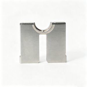

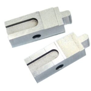


0.6 mm Pitch Connector Mold Inserts: Precision Workflow Advantages
A drawing-led workflow that connects DFM, critical-dimension planning, process selection, inspection, and revision control before production begins.
Drawing-Led DFM Review
We review drawings, models, datum schemes, tool access, and molding context to identify manufacturability questions before quotation or production commitments.
Critical Dimensions Planned
Critical-to-quality features are identified early, helping align tolerance priorities, measurement methods, and inspection expectations with the functional connector interface.
Process Route Selection
CNC machining, EDM, grinding, and fitting are considered as an integrated route based on geometry, material condition, access, and surface requirements.
Inspection Plan Alignment
Inspection planning links drawing requirements to appropriate measurement methods, documented results, and order-specific quality expectations for precision mold insert work.
Revision Visibility Maintained
Controlled project communication keeps drawing revisions, open technical questions, production status, and delivery information visible throughout the manufacturing workflow.
Fine-Pitch Tooling Focus
For 0.6 mm pitch connector mold inserts, engineering discussion addresses feature relationships, datum strategy, machining allowance, and electrode or wire-path needs.
Configurable Precision Manufacturing Families
Drawing-led process routes for connector tooling, precision mold components, stamping die components and custom machined parts, reviewed against critical dimensions and inspection requirements.

CNC Machining Services
Precision CNC machining services for drawing-defined parts requiring coordinated milling, turning, EDM, grinding and inspection. Quotation review considers material, datums, critical dimensions, surface requirements, quantity and delivery expectations before a process route is committed.
Upload a Drawing
CNC Milling
Custom CNC milling services for prismatic mold, tooling and machine components. Tool access, fixture strategy, remaining stock for grinding or EDM, and tolerance relationships are reviewed from the drawing and model before machining begins.
Upload a Drawing
CNC Turning
Precision CNC turning services for rotational components such as pins, sleeves, guide elements and custom shafts. The review addresses concentricity, runout, diameters, shoulder geometry, material condition and any finishing or grinding requirements.
Upload a Drawing
5-Axis Machining
5-axis CNC machining for geometries where multiple faces, compound angles or restricted tool access affect the process plan. SUUXIANG evaluates setup reduction, cutter reach, datum control and downstream EDM or grinding needs against the approved drawing.
Upload a Drawing
Swiss & Micro Machining
Swiss machining and micro machining for small, slender or detail-intensive components where handling, feature access and dimensional control require careful planning. Drawings are reviewed for diameter transitions, slot or hole features, deburring expectations and inspection practicality.
Upload a Drawing
Wire EDM Services & Sinker EDM Services
Wire EDM and sinker EDM services for hardened materials, narrow slots, internal profiles, sharp geometry and features unsuitable for conventional cutting alone. Electrode design, wire path, flushing, EDM allowance and finish requirements are established from the component drawing.
Upload a Drawing
Precision Grinding
Precision surface and profile grinding for controlled flatness, parallelism, profile geometry and final-size requirements. Grinding stock, heat-treatment sequence, datum references and inspection methods should be defined before the route is released.
Upload a Drawing
Mold Core & Cavity Inserts
Precision mold core and cavity inserts manufactured as configurable, drawing-based components rather than stock items. Material, heat treatment, shutoff geometry, cooling interfaces, EDM features, surface condition and critical dimensions guide the manufacturing and inspection plan.
Upload a Drawing
Ejector & Ejection Components
Ejector pins, sleeves and ejection components produced to the mold design’s dimensions, fits and operating context. Manufacturing review addresses running clearance, head and shoulder features, hardness requirements, surface condition, mating locations and wear-sensitive details.
Upload a Drawing
Core Pins, Guide & Locating Components
Core pins, guide pins and locating components made to drawing-defined geometry and functional datum relationships. SUUXIANG reviews pin diameter, seating features, positional requirements, material and heat treatment, grinding needs and mating-component information where available.
Upload a Drawing
Slides, Lifters, Gates & Mold Accessories
Mold slides, lifters, gates and accessories manufactured around the specific mold action and interface requirements. The process review considers travel surfaces, shutoffs, angles, lubrication provisions, mating geometry, heat treatment and final fitting or inspection needs.
Upload a Drawing
Connector Mold Components
Precision connector mold components for fine-pitch and high-density connector tooling, including inserts, cores, pins and locating features. Reviews focus on cavity detail, pitch relationships, EDM strategy, micro-feature access, material condition and inspection requirements.
Upload a Drawing
Stamping Die Components
Precision stamping die components for drawing-defined punch, die, guide, stripper and locating functions. Process planning considers material and hardness, cutting-edge geometry, clearance relationships, wire EDM access, grinding stock and inspection criteria.
Upload a Drawing
Injection Mold Components, MIM, CIM & Overmolding Tooling
Injection, MIM, CIM and overmolding tooling components manufactured within verified project scope. Drawings and application context inform review of cavities, cores, gates, inserts, material behavior, feature access, surface requirements and required inspection evidence.
Upload a Drawing
Machining Materials
CNC machining materials selected and processed according to the drawing, application and specified condition. RFQs should identify grade, supplied condition, heat-treatment requirement, corrosion or wear considerations, traceability needs and any approved material substitutions.
Upload a Drawing
Surface Finishes & Heat Treatment
Surface finishing and heat treatment planned as part of the component route, not added after dimensional decisions are fixed. Requirements should define the applicable treatment, target condition, coating or finish, masking needs, dimensional allowance and verification expectations.
Upload a Drawing
Quality, Metrology & Documentation
Precision inspection, metrology and quality documentation aligned to the order and agreed inspection plan. Critical dimensions, datums, measurement methods, revision status and reporting requirements are clarified before production so final records match the delivered parts.
Upload a Drawing
Prototyping & Low-Volume Production
Rapid prototyping and low-volume manufacturing for drawing-driven parts needing an appropriate process route before broader release. Quantity, material, critical dimensions, revision maturity, inspection needs and target date help determine practical CNC, EDM, grinding and fitting steps.
Upload a DrawingMaterials for 0.6 mm Pitch Connector Mold Insert Requirements

P20 Pre-Hardened Steel
A practical choice for moderate-volume connector tooling where stable machining and predictable polishing matter. Pre-hardened condition can streamline scheduling, while final suitability depends on cavity geometry, resin, wear zones, and required surface finish.

H13 Tool Steel
Often considered for inserts exposed to repeated thermal cycling or elevated molding temperatures. Its toughness supports demanding tooling details, but heat-treatment sequence, EDM strategy, grinding allowance, and dimensional verification require drawing-specific planning.

S136 Stainless Steel
A corrosion-resistant option for inserts where moisture, corrosive resins, or extended storage may affect tooling surfaces. It can support polished cavity requirements, subject to approved hardness, machining route, surface specification, and inspection criteria.

D2 Tool Steel
A wear-focused steel option for localized features subject to abrasion or repeated contact. Its hardness potential must be balanced against machinability, wire-EDM access, brittleness considerations, and the critical dimensions defined on the drawing.

Beryllium Copper Alloy
Used selectively where heat transfer or localized cooling response is important around fine connector details. Material grade, safety handling, insert geometry, molding environment, and mating components must be reviewed before committing to production.
Manufacturing Processes for 0.6 mm Pitch Connector Mold Inserts


Wire EDM Cutting
Wire EDM produces narrow slots, sharp internal profiles, and through features where conventional cutter access is restricted. A planned wire path and finishing strategy help preserve critical geometry while accounting for required stock and inspection datums.

Sinker EDM Forming
Sinker EDM forms deep cavities, fine ribs, and complex internal details that require electrode access rather than direct cutting. Electrode design, wear considerations, surface requirements, and subsequent finishing needs are aligned to the approved drawing.


Fitting and Assembly
Fitting checks how inserts, pins, slides, and related mold components interact at their mating interfaces. The work focuses on approved clearances, seating surfaces, movement requirements, and drawing-defined functional relationships before final inspection and shipment.

Dimensional Inspection
Inspection verifies drawing-defined critical dimensions, datum relationships, surface requirements, and requested reporting against the agreed plan. Results, revision status, and documentation are kept aligned with the order so engineering and quality teams can review traceable evidence.
Supporting Components for 0.6 mm Pitch Connector Mold Inserts

Guide Components
Guide pins, bushings, and related alignment parts can be specified to support repeatable mold movement. Selection is reviewed against plate construction, clearance, wear expectations, lubrication provisions, and assembly datum requirements.

Locating Elements
Locating pins, keys, and interlocking features help establish controlled relationships between inserts and mold plates. Their geometry is assessed for machining access, fitting sequence, tolerance stack, serviceability, and critical positioning needs.

Ejection Parts
Ejector pins, sleeves, and return-related parts may be matched to the component geometry and release strategy. Project review considers ejection contact areas, guide support, heat treatment, grinding needs, and inspection points.

Gate Inserts
Gate inserts and sprue-adjacent components can be configured around the agreed molding concept. SUUXIANG reviews gate location, material flow context, erosion risk, EDM access, finishing requirements, and replaceable-insert strategy.

Wear Components
Wear plates, support blocks, and sliding-contact components can be included where the mold design calls for controlled movement. Material choice, surface treatment, grinding stock, fit condition, and maintenance access require drawing-based review.
About 0.6 mm Pitch Connector Mold Inserts
SUUXIANG is the sole international-facing public brand of Dongguan SuuXiang Precision Mold Co., Ltd., established in 2010 in Chang’an Town, Dongguan, Guangdong, China. Founded by XiaoCheng Huang, the company helps global engineering and sourcing teams translate drawings, models and specifications into inspected precision components and connector-tooling work.
For 0.6 mm pitch connector mold inserts, production planning begins with DFM and critical-dimension review. Our practical workflow can combine CNC milling and turning, multi-axis machining, wire EDM, sinker EDM, precision grinding, fitting, and inspection according to the drawing, material, surface, datum, and revision requirements.
What differentiates SUUXIANG is disciplined project control rather than a generic parts catalog. We review machining access, EDM strategy, grinding stock, heat-treatment sequence, and inspection expectations before production commitments, then keep revision, quality, and delivery information visible throughout the manufacturing process.

0.6 mm Pitch Connector Mold Inserts: Controlled Production
DFM and Datum Review
Before quotation, SUUXIANG reviews the drawing, model, mating context, critical dimensions, datum scheme, surface requirements and tolerances. This early review identifies access constraints and tolerance-stack risks so the production route is based on defined engineering priorities rather than assumptions.
- Confirm critical-to-quality dimensions and functional datums
- Review wall geometry, tool access and machining sequence
- Identify heat-treatment, surface and inspection requirements
- Align revision status before production planning

CNC and EDM Route Planning
Fine-pitch connector tooling often requires more than a single machining operation. SUUXIANG plans the appropriate combination of CNC milling, turning where applicable, wire EDM, sinker EDM and electrode strategy around geometry, material condition, internal features and required finish.
- Select processes according to feature geometry and access
- Plan wire paths for narrow profiles and precise contours
- Define electrode strategy for EDM-required details
- Preserve machining allowances for downstream operations

Grinding and Functional Fitting
Grinding and fitting are planned as controlled finishing stages when insert function, bearing surfaces or dimensional relationships require them. The objective is to protect critical geometry while allowing mating components to be evaluated against the approved drawing and applicable assembly requirements.
- Set grinding stock before heat treatment and finishing
- Control reference surfaces for repeatable location
- Check mating relationships during fitting when specified
- Address functional contact areas without obscuring datum control

Inspection and Revision Traceability
Inspection planning follows the order requirements and identified critical dimensions for 0.6 mm pitch connector mold inserts. SUUXIANG keeps drawing revisions, inspection expectations and delivery coordination visible throughout the project, helping teams compare the finished component with the released manufacturing definition.
- Match inspection methods to critical features
- Record results against the agreed inspection plan
- Maintain clear drawing and revision identification
- Coordinate final documentation with order requirements

Why Engineering Teams Choose SUUXIANG
A drawing-led workflow for 0.6 mm pitch connector mold inserts, built around DFM review, controlled revisions and inspection planning.
← Swipe left or right to view →
0.6 mm Pitch Connector Mold Insert Production Process
A controlled sequence that aligns DFM, critical-dimension planning, precision machining and documented delivery coordination.
Review Drawings and Requirements
We review 2D and 3D data, material, quantity, datums, critical dimensions, surface requirements, inspection needs and target delivery before confirming the process route.
Plan DFM and Process
Engineers assess tool access, tolerance stack, heat-treatment sequence, machining allowance, electrode strategy, wire path and grinding stock, then resolve manufacturability questions with your team.
Machine Critical Insert Features
The approved plan guides CNC milling, turning, multi-axis or micro-machining operations, keeping revision-controlled drawings and feature priorities visible throughout production.
Apply EDM and Grinding
Wire EDM, sinker EDM and precision grinding are applied where geometry, corner conditions, finish requirements or dimensional control call for those specialized operations.
Inspect Pack and Coordinate
Parts are inspected against the agreed plan, documented as required, protected for shipment and coordinated with you using visible revision and delivery information.
How to Work With SUUXIANG on 0.6 mm Pitch Connector Mold Inserts
A drawing-led workflow that aligns DFM, critical dimensions, inspection expectations, revision control, and delivery coordination before production begins.
Submit Your Requirements
Provide 2D drawings, available 3D models, material, quantity, critical dimensions, surface requirements, target date, and inspection needs for a focused technical review.
Review DFM and Quote
Confirm datum strategy, machining access, EDM or grinding requirements, heat-treatment sequence, inspection approach, and revision status before SUUXIANG issues a production-aligned quotation.
Approve First Articles
Where the project requires it, review samples or first-article evidence against agreed critical dimensions, materials, and documentation requirements before releasing the production plan.
Coordinate Production and Delivery
Follow controlled machining, EDM, grinding, fitting, inspection, and delivery coordination with visible revision information and final documentation matched to the verified order requirements.
Certifications and Quality Documentation

Verified Customer Feedback and Project Outcomes
[PLACEHOLDER] Present three approved customer testimonials or case summaries only when attributable feedback and outcome evidence are available; do not fa
0.6 mm Pitch Connector Mold Insert FAQ
Practical answers for teams preparing a drawing-led connector tooling inquiry.
What information should I send for a 0.6 mm pitch connector mold insert quote?
Is there a minimum order quantity for 0.6 mm pitch connector mold inserts?
How is lead time assessed for 0.6 mm pitch connector mold inserts?
Can SUUXIANG make samples before a larger connector tooling order?
What inspection documentation can be requested with a connector mold insert order?
How does SUUXIANG handle drawing revisions and confidential connector designs?
What payment and shipping details should I confirm before placing an order?
Can you quote from a PDF drawing only, or is a 3D model required?
Buyer’s Guide to 0.6 mm pitch connector mold inserts
Use a practical decision framework to specify precision inserts, compare supplier capabilities, control tolerance and material risks, and avoid sourcing mistakes that delay connector-tooling validation and production.
1. What Are 0.6 mm Pitch Connector Mold Inserts?
0.6 mm pitch connector mold inserts are drawing-defined, replaceable precision elements that form, locate, or shut off fine-pitch connector features in an injection-molding tool. The 0.6 mm value normally denotes nominal contact center-to-center spacing; it does not describe a finished connector, a stamped terminal, or a complete mold base.
At 0.6 mm, small errors in pin or cavity location can affect contact alignment, plastic wall balance, shutoff integrity, flash risk, and repeatability across cavities. Buyers are purchasing the insert geometry and its controlled interfaces: datum faces, pocket or retainer fit, contact-feature positions, mating shutoffs, gate-adjacent surfaces, vent details, and specified finish.
Since 2010, SUUXIANG has used drawing review to clarify which dimensions are critical before selecting CNC, EDM, grinding, fitting, and inspection steps. A usable RFQ should identify the mating insert or mold plate, datum scheme, material and heat-treatment state, critical pitch-related dimensions, surface requirements, and revision level; 0.6 mm pitch is used in commercial connector products, for example https://www.amphenol.com/products/all/all-markets/robotics?PageSize=50&pagenumber=30.
2. Evolution of Fine-Pitch Connector Tooling
0.6 mm pitch is used in compact board-to-board and FPC connector families, where contact density and small molded geometry leave little room for datum drift. For example, a Fujikura DFZ-series listing identifies a 0.6 mm-pitch board-to-board application: https://mono.ipros.com/en/company/detail/2114879/category/69315
0.6 mm contact pitch also appears in high-contact-count interconnect systems; Amphenol describes an OSFP system with 60 contacts per port at that pitch: https://www.amphenol.com/products/all/all-markets/robotics?PageSize=50&pagenumber=30. For tooling buyers, miniaturization shifts attention from nominal pitch alone to a shared datum scheme, feature-to-feature tolerance stack, tool-access limits, and a measurable inspection plan.
100-plus-cavity molding is publicly described for some precision molded components: https://www.connectpositronic.com/literature/65026. Higher cavitation can multiply the effect of insert variation, wear, venting differences, and handling damage, so qualification should define cavity identification, sampling logic, mating-function checks, revision control, and acceptance evidence before production release.
3. Types of 0.6 mm Pitch Connector Mold Inserts
At 0.6 mm pitch, insert roles should be separated by the feature that establishes geometry, forms plastic, guides motion, or requires periodic replacement. The drawing should identify each insert’s datum and mating interface before the mold layout is frozen.
Cavity Inserts
At 0.6 mm pitch, cavity inserts define exterior plastic geometry and shutoff faces. Gate erosion, flash at shutoffs, and polish damage favor replaceable cavity details when localized features are high-wear.
Core Inserts

At 0.6 mm pitch, core inserts form internal slots, ribs, and contact-clearance geometry. Core deflection and wear at mating shutoffs make modular cores preferable where one critical feature needs adjustment or replacement.
Terminal-Forming Inserts
At 0.6 mm pitch, terminal-forming inserts control the molded relationship to metal terminals or retention features. Abrasion from terminals and dimensional drift at locating surfaces justify replaceable forming tips.
Slides And Lifters
At 0.6 mm pitch, slide or lifter details create undercuts that cannot release in the opening direction. Cam interfaces, guide faces, and small shutoffs wear under repeated motion; modular details simplify fitting after service.
Gate And Runner Inserts
At 0.6 mm pitch, gate and runner inserts control melt entry and balance into fine features. Gate-edge erosion, contamination, and thermal damage favor replaceable tips when gate geometry is critical to fill consistency.
4. Materials for 0.6 mm Pitch Connector Mold Inserts
At 0.6 mm pitch, insert material must resist localized wear without sacrificing edge integrity or polish quality. Selection should follow resin, geometry, production volume, and drawing-defined surface or corrosion requirements.
| Material Route | Primary Benefit | Key Tradeoff |
|---|---|---|
| Hardened tool steel | Wear resistance and edge retention | Corrosion protection may be needed |
| Corrosion-resistant steel | Moisture and resin resistance | Polishability and heat treatment require review |
| High-conductivity alloy | Localized heat transfer | Lower wear resistance in contact zones |
| Coating or polish | Release, wear, or surface control | Must match geometry and maintenance access |
Steel Selection
Hardened tool steels suit high-contact wear; corrosion-resistant grades suit humid processing or corrosive resins. Toughness matters where thin ribs, pins, or sharp EDM details face chipping risk.
Thermal And EDM Tradeoffs
High-conductivity alloys can shorten cooling paths in localized areas, but require review for strength, wear, and joining strategy. EDM response, recast removal, and grinding stock should be planned before hardening.
Finish And Maintenance
Polishing supports resin release and cosmetic surfaces, while coatings may reduce adhesion or abrasive wear. Specify finish direction, accessible polish areas, and maintenance criteria on the drawing or inspection plan.
5. Custom Features for Connector Mold Inserts
At 0.6 mm pitch, customization is functional: it establishes how molten resin fills, how terminals remain protected, and how insert revisions remain identifiable. Freeze feature ownership before selecting the machining route.
Datums and Segmentation
At 0.6 mm pitch, primary, secondary, and tertiary datums must locate cavity details, terminal windows, and mating interfaces from the same drawing scheme. Segmented inserts can simplify replacement, but joint lines must not create flash-risk edges near critical terminal areas.
Flow and Protection Features
Gate position, land geometry, and vent depth affect fill balance, weld-line location, and gas evacuation. Freeze these details before CNC, EDM, or polishing because later changes can alter steel conditions, electrode strategy, and terminal-area protection.
Specified surface finish should identify the functional area, direction, and allowable texture rather than request a general polish. Texture is normally excluded from sealing faces, shutoffs, and fine terminal-forming details unless the drawing defines its boundary.
Marks and Service Access
Engraved cavity IDs, revision marks, and orientation symbols support traceability during molding, inspection, and maintenance. Define character height, depth, location, and viewing orientation so marks do not weaken thin steel or print onto an unintended cosmetic surface.
Before release, freeze material condition, heat-treatment sequence, datum callouts, critical dimensions, finish, venting, gate geometry, split lines, and identification requirements. SUUXIANG can use that controlled package to align machining, EDM, grinding, fitting, and inspection planning.
6. Quality Elements in Connector Insert Construction
At 0.6 mm pitch, construction controls must be specified against functional datums, not nominal geometry alone. The drawing should define what is measured, how it is fixtured, and which deviations require disposition.
Datums And Stack-Up
Two or more functional datums should locate every pitch-critical feature and alignment interface. Unrelated machining references can create cumulative pitch error.
0.6 mm pitch requires a documented tolerance stack including insert location, pin position, and mating features. Verify it by measured coordinates, not visual fit.
Shutoffs And Edges
Sharp shutoffs need defined corner radii, edge-break limits, and surface-condition requirements. Excessive radii or damaged edges can open a flash path.
Polished flow surfaces and specified vent depth should be reviewed together. A blocked vent can contribute to short shots, while an uncontrolled vent can flash.
Distortion And Inspection Access
Heat treatment can change geometry, so grinding stock and post-treatment inspection datums belong on the process plan. Measure pitch-critical features after the final dimensional operation.
Three inspection provisions matter: probe access, stable fixturing, and a revision-controlled report format. These controls support interchangeability and help detect alignment conditions that can damage pins.
7. Choosing a 0.6 mm Pitch Connector Mold Insert Supplier
A capable supplier evaluates 0.6 mm pitch connector mold inserts from the controlled drawing package, not pitch alone. Request evidence that links each critical feature to a feasible process and inspection method.
| Stage | Primary Evaluation Evidence | Decision Focus |
|---|---|---|
| Prototype | DFM and first-article report | Learning speed |
| Bridge | Setup and repeatability records | Controlled iteration |
| Production | Inspection plan and corrective-action process | Sustained traceability |
Start With DFM Evidence
2D drawings, 3D models, datum definitions, and mating context should produce a written DFM response. Ask for the proposed CNC, wire-EDM, sinker-EDM, and grinding route, including tool access, electrode strategy, and finishing allowances.
Control Revisions And Inspection
One released revision should govern the quotation, sample, and shipment records. Request a ballooned drawing, measurement report, material identification evidence, and an inspection plan identifying instruments, datums, sampling, and report format.
24-hour change acknowledgement is a practical communication target; agree the actual response cadence before order release. Require documented containment, root-cause analysis, corrective action, and verification when a nonconformance occurs.
Match Evidence To Tooling Stage
Prototype work needs rapid process feedback and dimensional learning; bridge tooling needs repeatable setup records; production tooling needs stable revision, wear-risk, and replacement-part planning. Review representative sample documentation before expanding scope.
8. Common 0.6 mm Pitch Connector Mold Insert Mistakes
At 0.6 mm pitch, small definition gaps can become nonconforming cavities, pins, or molded contact features. Resolve these items during drawing review, before machining, heat treatment, or EDM programming.
Define Datums And Tolerances
At 0.6 mm pitch, dimensions without a common datum scheme invite stack-up error. Ask for a 2D drawing that identifies functional datums, CTQ features, and unambiguous profile or positional tolerances.
For resin features, require the resin grade, shrinkage basis, flow direction, and mating-feature target. This prevents an insert being correct to its drawing but wrong after molding.
Match Steel And Finish
For each insert, steel selection must follow wear, corrosion, polish, EDM, and heat-treatment requirements—not a generic material note. Request the approved material specification and heat-treatment sequence before the process route is released.
Functional polish is not merely cosmetic. Define the surface requirement by location, including texture, release need, flash sensitivity, and permitted EDM or grinding condition.
Plan Inspection And Trials
Before production, define which dimensions require CMM, vision, pin-gauge, or functional verification and what report format is required. An inspection plan prevents acceptance disputes after parts are complete.
At first-off approval, run an assembly or molding trial using relevant mating components where feasible. Freeze revision-controlled drawings, models, and change records before machining; late changes can require remachining, new electrodes, or a revised qualification cycle.
9. From Drawing to Qualified Connector Tooling
A controlled launch for 0.6 mm pitch connector mold inserts begins before machining release. One cross-functional owner should close each checkpoint so drawing, inspection, and trial feedback remain aligned.
Freeze The Requirements Package
2D drawings, 3D models, datum scheme, mating context, material, hardness, quantities, and revision status form the release package. Engineering owns functional intent; procurement owns the commercial request.
One critical-dimension register should identify pitch-related features, surface priorities, and inspection evidence. Quality approves measurable acceptance criteria before quotation.
Review DFM And Quotation
One supplier DFM review should confirm tool access, EDM or wire path, grinding stock, heat-treatment sequence, and inspection method. The tooling supplier records risks; engineering approves any dimensional or datum change.
Three aligned records—quotation, drawing revision, and process route—prevent assumptions from entering production. Procurement confirms scope, delivery milestones, and change-control terms.
Approve First Article And Trial
First-article inspection compares agreed critical dimensions against the released drawing and inspection plan. Quality accepts the report; engineering decides whether deviations affect fit, molding, or connector performance.
One mold-trial feedback package should capture defects, settings, cavity observations, and corrective actions. The supplier issues the revised record before the next release.
Control Revisions And Handoff
One revision log links every drawing change to affected inserts, inspection requirements, and delivery status. Program management owns approval routing across engineering, quality, procurement, and supplier teams.
Final handoff includes approved drawings, inspection records, material and process evidence when specified, and maintenance notes. The tooling supplier identifies replacement or rework triggers through the agreed traceability record.
10. Pricing 0.6 mm Pitch Connector Mold Inserts
0.6 mm pitch makes pricing sensitive to feature geometry, tolerance stack, datum access, material condition, heat treatment, EDM strategy, finishing, inspection, and revision risk. SUUXIANG should quote from the controlled drawing package rather than publish unit prices that omit these variables.
Three quantity bands change the cost structure: prototypes concentrate programming, setup, electrodes, and first-article inspection; repeat quantities spread those costs across parts. A complete RFQ should identify critical dimensions, mating context, material and hardness, surface requirements, quantity, target date, and required inspection records.
| Quantity band | Primary cost drivers | Lead-time factors | Quote inputs required |
|---|---|---|---|
| Prototype, 1–5 pieces | Programming, setup, EDM electrodes, first-article inspection | Material availability, heat-treatment sequence, electrode and wire path | 2D/3D files, CTQs, datum scheme, material, inspection plan |
| Low volume, 6–50 pieces | Cycle time, grinding stock, fixture needs, inspection sampling | Setup reuse, batch heat treatment, revision status | Quantity breaks, finishing, reporting, delivery target |
| Production support, 51+ pieces | Process repeatability, dedicated fixturing, wear replacement | Capacity confirmation, material lot control, change control | Forecast, approved revision, traceability and receiving requirements |
Upload Drawings for 0.6 mm Pitch Connector Mold Inserts
Send 2D or 3D files, material, quantity, critical dimensions, quality requirements, and target delivery date for a disciplined drawing review.