
Precision Mold Components Built to Your Approved Drawing
Custom cores, cavities, inserts and connector-tooling parts planned around critical dimensions, machining access, heat treatment and inspection requirements.
Representative Parts for Precision Mold Components


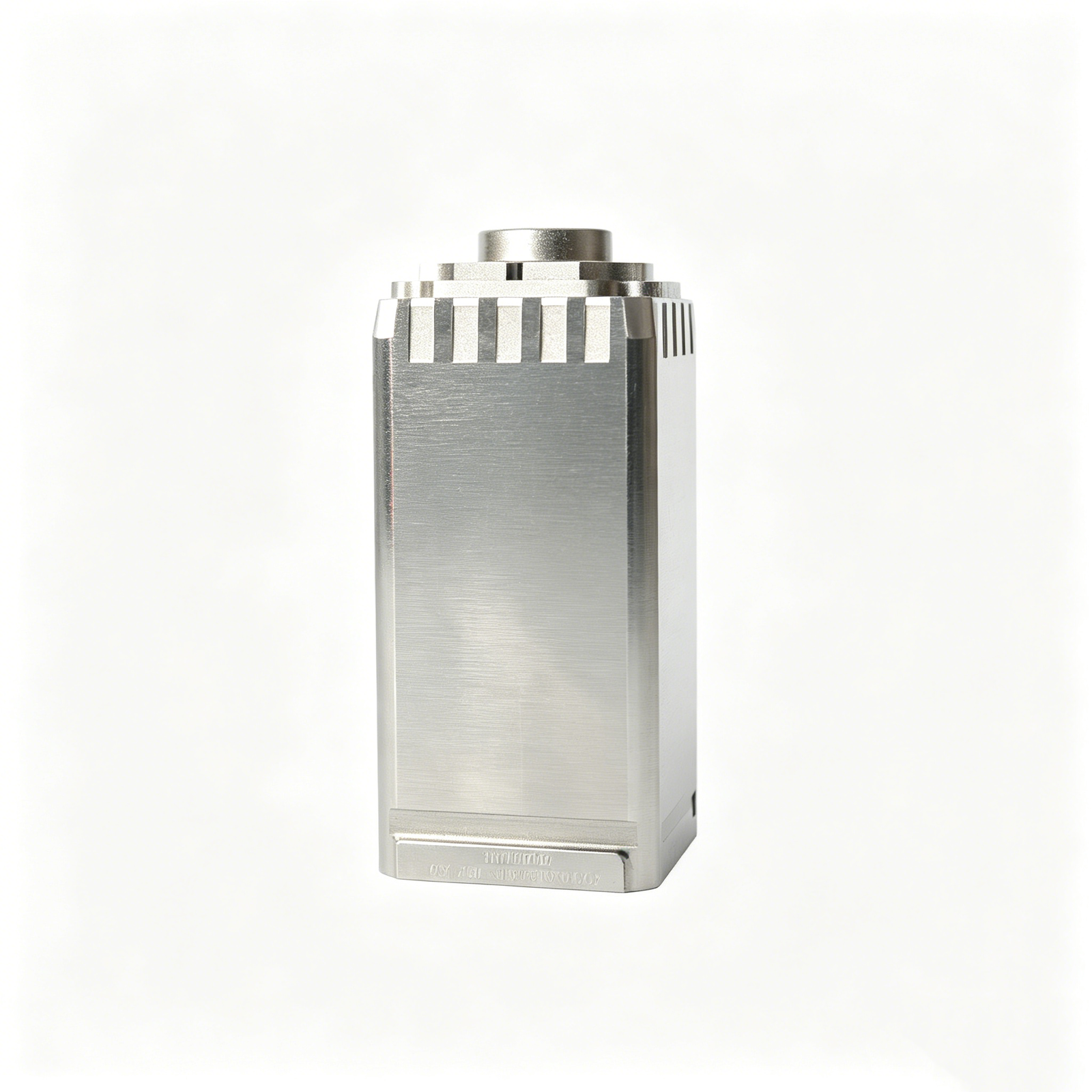





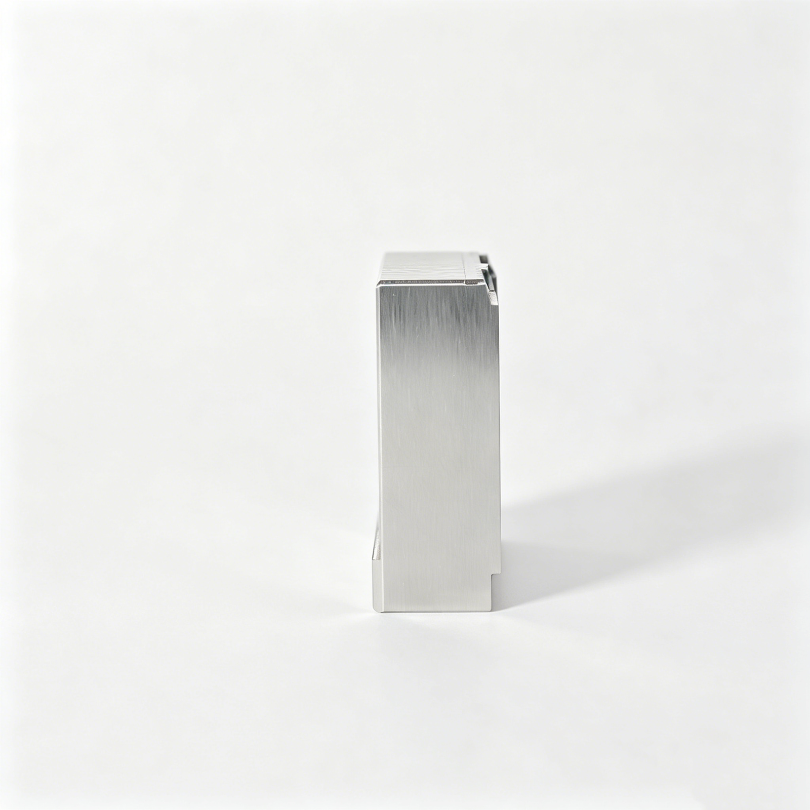

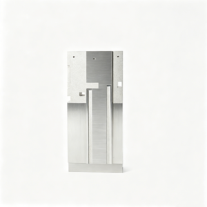
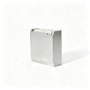
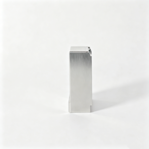
Sample Components for Precision Mold Components
Ten drawing-based component examples; open a part to review its engineering context.





Engineering Controls for Precision Mold Components
Critical tooling parts are planned around approved drawings, mating conditions and inspection expectations before production begins.
Drawing Review
We review critical dimensions, surface requirements, tool access and revision details before selecting a manufacturing route for custom tooling parts.
Datum Strategy
Datum schemes are aligned with fit, shutoff and mating relationships so machining and inspection reference the same functional intent.
Process Route Planning
CNC, EDM, grinding and fitting steps are sequenced around steel condition, geometry, allowance and required feature access.
EDM and Grinding Coordination
Electrode strategy, wire paths and grinding stock are considered together for corners, ribs, venting features and hardened-tooling requirements.
Inspection Planning
Inspection methods are defined for critical form, position, flatness, parallelism and mating conditions according to the approved drawing.
Revision Traceability
Every component follows the approved drawing revision, with project communication and final documentation matched to the verified inspection plan.
Related Paths for Precision Mold Components
Custom components and process routes organized around fit, shutoff, ejection, guidance, feature access and inspection requirements.
CNC Machining Services
Drawing-defined machining for custom parts, with process planning around geometry, material condition, datums and inspection access.
Explore CNCPrecision Mold Components
Core, cavity and insert work planned around mating features, material state, EDM, grinding and fitting requirements.
Explore Mold PartsQuality and Documentation
Discuss CTQ features, measurement methods, revision control and the release documents required for your order.
Review QualityMaterials for Precision Mold Components
Pre-Hardened Tool Steel
A practical option for cores, cavities, slides and inserts requiring stable machining before final fitting. Its supplied steel condition can reduce post-machining movement, while drawing-defined hardness, polish and inspection requirements still govern selection.
Through-Hardening Tool Steel
Used for punches, sleeves, core pins and wear-focused tooling details where hardness is planned with grinding stock and EDM strategy. Heat-treatment sequence, datum preservation and final dimensional verification must be established before production.
Corrosion-Resistant Tool Steel
Considered for tooling exposed to moisture, corrosive resins or storage conditions where stain resistance and polishability matter. The approved drawing should clarify steel grade, hardness condition, surface finish and any mating-component constraints.
High-Wear Tool Steel
Suitable for configurable punches, gates, inserts and sliding features subject to repeated contact or abrasion. Material choice is evaluated alongside corner geometry, thin ribs, venting, heat treatment, grinding allowance and inspection method.
Stainless Steel Alloys
Often evaluated for corrosion-sensitive connector tooling and precision mold components where cleanability or environmental exposure influences material choice. Confirm the exact grade, condition, machining approach and dimensional priorities through the drawing-upload RFQ.
Precision Mold Components: Processes Matched to Your Drawing
CNC Milling and Turning
Milling and turning establish core geometry, sleeves, punches, locating features and profiles. Tool access, datum references and planned stock are reviewed early so later heat treatment, EDM and grinding steps retain functional relationships.
Multi-Axis Machining
Multi-axis machining supports angled features, complex cavity surfaces, connector inserts and difficult approach paths. The process route is considered with clamping strategy, thin ribs, corners and mating conditions to reduce unnecessary setups and datum transfer.
Wire EDM Cutting
Wire EDM produces precise profiles, narrow slots, sharp internal geometry and hardened-section features where conventional tools cannot reach. Wire path, start holes, skim-cut strategy and inspection points are planned against the drawing’s functional dimensions.
Sinker EDM Forming
Sinker EDM forms deep cavities, fine ribs, detailed corners and inaccessible internal features using a defined electrode strategy. Electrode wear, spark clearance, surface requirement and finishing allowance are reviewed with the steel and heat-treatment condition.
Precision Grinding Operations
Precision grinding controls flatness, parallelism, size and surface condition on precision mold components after machining or heat treatment. Grinding stock and datum sequence are planned to protect shutoffs, guiding surfaces and other mating relationships.
Fitting and Inspection
Fitting and inspection verify assembly behavior, form, position and critical mating conditions before release. Measurement methods and reporting requirements are aligned to the approved drawing revision, helping procurement and quality teams maintain traceable acceptance evidence.
Precision Mold Components: Tooling Accessories and Assembly Details
Guide Elements
Guide pins, bushings and locating elements help establish repeatable alignment between mold halves, inserts and mating assemblies. Selection should be reviewed against datum strategy, wear conditions, assembly access and required positional inspection.
Ejector Parts
Ejector pins, sleeves and related ejection components are configured to the approved drawing for release, support and clearance requirements. Fit, hardness condition, grinding stock and mating surfaces should be defined before machining begins.
Tooling Springs
Springs can support return, preload and controlled movement within mold or die assemblies. Specify the installation space, operating conditions, required travel and any assembly constraints so the accessory selection supports the intended mechanism.
Assembly Fasteners
Custom or specified fasteners, dowels and retaining features support secure assembly of cores, cavities, slides and inserts. Thread engagement, access direction, counterbore details and tolerance relationships should be coordinated with the component drawing.
Replaceable Inserts
Replaceable inserts allow wear-prone, detailed or revision-sensitive areas to be serviced without remaking a larger tooling section. Their seating faces, locating scheme, shutoff relationships and inspection criteria require coordinated planning.
Identification Features
Part marks, revision identification and traceability features help distinguish similar precision mold components during assembly, inspection and replacement. Location, marking method and legibility requirements should be included in the approved drawing or RFQ notes.
About SUUXIANG Precision Manufacturing
SUUXIANG is the public brand of Dongguan SuuXiang Precision Mold Co., Ltd., founded in 2010 in Chang’an, Dongguan. XiaoCheng Huang is the founder and legal representative. The company works with engineering, tooling, procurement and quality teams on drawing-defined precision components.
The work combines CNC machining with precision mold components, connector tooling, EDM, grinding, fitting and inspection planning. A process route is selected around the actual geometry, material state, datum scheme, critical features and the documents required by the order.
Visitors should use the representative part photos to understand part families, not to infer an exact grade, tolerance or measured result. For a technical discussion, prepare the current drawing and model, quantity, material, finish, CTQs, inspection scope and target date.
How SUUXIANG Plans Critical Precision Mold Components
DFM Starts With Datums
Each precision mold component begins with the approved drawing, revision, and functional datums. SUUXIANG reviews tolerance stacks, tool access, shutoff relationships, venting needs, and mating context before selecting a practical machining and inspection route.
- Confirm critical-to-quality dimensions and datum references
- Review machining access for ribs, corners, and internal details
- Identify fit, shutoff, and mating risks before release
- Keep drawing revisions visible through production
Heat Treatment Needs Allowance
Steel condition, heat-treatment sequence, and grinding stock are planned together because each affects final geometry. The process route considers where material must remain for finishing, how distortion may affect datums, and which surfaces require controlled grinding after heat treatment.
- Define pre-hard or post-hard machining sequence
- Reserve grinding stock on critical finished faces
- Protect datum relationships through heat-treatment stages
- Align material requirements with the approved drawing
EDM Strategy for Fine Details
Micro-features, thin ribs, deep corners, and difficult tool access may require wire EDM or sinker EDM. SUUXIANG evaluates electrode strategy, wire path, flushing, surface expectations, and downstream fitting requirements so EDM supports the intended component function.
- Assess wire paths for narrow slots and profiles
- Plan electrode access for enclosed geometry
- Consider venting and corner-detail requirements
- Coordinate EDM surfaces with fitting and finishing
Inspect Mating Conditions
Inspection planning extends beyond isolated dimensions when components must work together. The agreed method can address form, position, flatness, parallelism, critical fits, and mating conditions, with final records aligned to the order, drawing revision, and verified inspection plan.
- Define inspection methods for critical characteristics
- Check form and position against functional datums
- Review flatness and parallelism where assembly depends on them
- Match documentation to agreed quality requirements
Precision Mold Components RFQ Decision Checklist
Compare quotations by the same drawing revision and stated technical scope, not by an unqualified unit price.
← Swipe left or right to view →
Controlled Workflow for Precision Mold Components
Each custom component follows the approved drawing and revision, with manufacturing decisions and inspection requirements aligned before production.
Review Drawings and Requirements
Review 2D drawings, models, material, quantity, application, critical dimensions, datums, surface requirements, heat treatment, inspection needs, and target delivery date.
Plan Process and Controls
Select CNC, EDM, grinding, fitting, and inspection routes while confirming tool access, machining allowance, electrode strategy, wire path, and revision controls.
Machine Critical Features
Produce cores, cavities, inserts, pins, slides, lifters, punches, sleeves, and connector tooling parts through the planned machining and EDM sequence.
Fit, Finish, and Inspect
Apply required fitting and finishing, then inspect critical form, position, flatness, parallelism, dimensions, and mating conditions against the approved inspection plan.
Document, Pack, and Coordinate
Match final documentation to verified inspection results, protect finished components for shipment, and keep revision and delivery coordination visible through dispatch.
Start Your Precision Mold Components Project
Move from drawing review to controlled production with requirements, revision details and inspection expectations aligned before machining begins.
Review Sample Parts Package
Send 2D drawings, 3D models, material and heat-treatment requirements, quantities, delivery targets, critical dimensions, surface priorities and any mating-component context.
Review Manufacturability Together
Confirm datum strategy, tolerance stack, tool access, grinding stock, EDM approach, venting details, inspection methods and revision status before quotation is finalized.
Approve the Production Plan
Review the proposed process route, pricing, lead-time assumptions and documentation needs; approve samples or first-article checks when the project requires them.
Release Controlled Production
Machining, EDM, grinding, fitting and inspection proceed to the approved drawing revision, with final records matched to the agreed inspection plan.
Project Documentation to Define Before Production
Questions Buyers Should Ask During Technical Review
Which drawing revision and datum scheme will govern the part, and how will a proposed deviation be approved?
Which features are critical to function, and what measurement method will demonstrate conformity?
Does the quotation include material condition, secondary processes, inspection documents and packing assumptions?
Precision Mold Components FAQ
Practical answers on RFQ inputs, planning, inspection, delivery, and controlled revisions.
What information do you need to quote precision mold components?
Is there a minimum order quantity for precision mold components?
Can I order samples before production of precision mold components?
How should I plan lead time for custom tooling parts?
How do you select material and heat treatment for mold cores, inserts, and punches?
What inspection reports are available for precision mold components?
How are precision mold components shipped internationally?
How do payment, drawings, and IP protection work for a custom order?
Precision Mold Component Buyer’s Guide
A practical decision framework for a custom mold core, cavity or insert, from the first drawing review to documented acceptance.
1. Identify the mold component role
Identify whether the drawing describes a core, cavity, insert, pin, slide or replacement wear component; the part role determines its mating surfaces. When specifying a custom mold core, cavity or insert, this decision should be recorded against the latest controlled drawing. Note the quantity, production stage and functional interface so the discussion remains about the actual component rather than a visually similar example. A photograph can identify a part family, but it cannot establish material, tolerance or inspection results.
For this stage, focus on mating relationships, wear surfaces, steel condition, EDM details and fitting requirements. Ask how the proposed process will preserve datum relationships and how the completed feature can be measured. If a tolerance, finish, hardness or document is essential, include its acceptance method in the RFQ rather than leaving it to interpretation.
Before approving production, record the drawing revision, any clarification or agreed deviation, and the documents expected with the order. Compare quotations by the same technical scope: material condition, operations, sampling, inspection, finishing, packing and delivery assumptions. If an item is not yet verified, treat it as an open engineering question. A clear decision record makes a prototype review and a later repeat order easier to reconcile without silently changing the specification.
2. Control the mating drawing set
Send the assembly context and mating-part references where possible so shutoffs, guide relationships and replacement interfaces are not judged in isolation. When specifying a custom mold core, cavity or insert, this decision should be recorded against the latest controlled drawing. Note the quantity, production stage and functional interface so the discussion remains about the actual component rather than a visually similar example. A photograph can identify a part family, but it cannot establish material, tolerance or inspection results.
For this stage, focus on mating relationships, wear surfaces, steel condition, EDM details and fitting requirements. Ask how the proposed process will preserve datum relationships and how the completed feature can be measured. If a tolerance, finish, hardness or document is essential, include its acceptance method in the RFQ rather than leaving it to interpretation.
Before approving production, record the drawing revision, any clarification or agreed deviation, and the documents expected with the order. Compare quotations by the same technical scope: material condition, operations, sampling, inspection, finishing, packing and delivery assumptions. If an item is not yet verified, treat it as an open engineering question. A clear decision record makes a prototype review and a later repeat order easier to reconcile without silently changing the specification.
3. Select steel and heat treatment
Tool-steel grade, stock condition and heat treatment affect machining allowance, EDM behavior, grinding sequence and the final inspection method. When specifying a custom mold core, cavity or insert, this decision should be recorded against the latest controlled drawing. Note the quantity, production stage and functional interface so the discussion remains about the actual component rather than a visually similar example. A photograph can identify a part family, but it cannot establish material, tolerance or inspection results.
For this stage, focus on mating relationships, wear surfaces, steel condition, EDM details and fitting requirements. Ask how the proposed process will preserve datum relationships and how the completed feature can be measured. If a tolerance, finish, hardness or document is essential, include its acceptance method in the RFQ rather than leaving it to interpretation.
Before approving production, record the drawing revision, any clarification or agreed deviation, and the documents expected with the order. Compare quotations by the same technical scope: material condition, operations, sampling, inspection, finishing, packing and delivery assumptions. If an item is not yet verified, treat it as an open engineering question. A clear decision record makes a prototype review and a later repeat order easier to reconcile without silently changing the specification.
4. Plan CNC and EDM sequence
Machine reference faces before hardening where appropriate, then plan electrodes, spark gaps, wire paths and finishing operations around accessible geometry. When specifying a custom mold core, cavity or insert, this decision should be recorded against the latest controlled drawing. Note the quantity, production stage and functional interface so the discussion remains about the actual component rather than a visually similar example. A photograph can identify a part family, but it cannot establish material, tolerance or inspection results.
For this stage, focus on mating relationships, wear surfaces, steel condition, EDM details and fitting requirements. Ask how the proposed process will preserve datum relationships and how the completed feature can be measured. If a tolerance, finish, hardness or document is essential, include its acceptance method in the RFQ rather than leaving it to interpretation.
Before approving production, record the drawing revision, any clarification or agreed deviation, and the documents expected with the order. Compare quotations by the same technical scope: material condition, operations, sampling, inspection, finishing, packing and delivery assumptions. If an item is not yet verified, treat it as an open engineering question. A clear decision record makes a prototype review and a later repeat order easier to reconcile without silently changing the specification.
5. Protect fine ribs and small features
Fine ribs, small radii and narrow slots need explicit edge and surface requirements; a photograph cannot certify those dimensions. When specifying a custom mold core, cavity or insert, this decision should be recorded against the latest controlled drawing. Note the quantity, production stage and functional interface so the discussion remains about the actual component rather than a visually similar example. A photograph can identify a part family, but it cannot establish material, tolerance or inspection results.
For this stage, focus on mating relationships, wear surfaces, steel condition, EDM details and fitting requirements. Ask how the proposed process will preserve datum relationships and how the completed feature can be measured. If a tolerance, finish, hardness or document is essential, include its acceptance method in the RFQ rather than leaving it to interpretation.
Before approving production, record the drawing revision, any clarification or agreed deviation, and the documents expected with the order. Compare quotations by the same technical scope: material condition, operations, sampling, inspection, finishing, packing and delivery assumptions. If an item is not yet verified, treat it as an open engineering question. A clear decision record makes a prototype review and a later repeat order easier to reconcile without silently changing the specification.
6. Define grinding and fitting
State which faces are fitted, ground, polished or left as-machined, and how the completed insert should be checked against its mating component. When specifying a custom mold core, cavity or insert, this decision should be recorded against the latest controlled drawing. Note the quantity, production stage and functional interface so the discussion remains about the actual component rather than a visually similar example. A photograph can identify a part family, but it cannot establish material, tolerance or inspection results.
For this stage, focus on mating relationships, wear surfaces, steel condition, EDM details and fitting requirements. Ask how the proposed process will preserve datum relationships and how the completed feature can be measured. If a tolerance, finish, hardness or document is essential, include its acceptance method in the RFQ rather than leaving it to interpretation.
Before approving production, record the drawing revision, any clarification or agreed deviation, and the documents expected with the order. Compare quotations by the same technical scope: material condition, operations, sampling, inspection, finishing, packing and delivery assumptions. If an item is not yet verified, treat it as an open engineering question. A clear decision record makes a prototype review and a later repeat order easier to reconcile without silently changing the specification.
7. Inspect functional interfaces
A functional interface may need true position, profile, flatness or matched dimensions; choose a measurement setup that reproduces the drawing datums. When specifying a custom mold core, cavity or insert, this decision should be recorded against the latest controlled drawing. Note the quantity, production stage and functional interface so the discussion remains about the actual component rather than a visually similar example. A photograph can identify a part family, but it cannot establish material, tolerance or inspection results.
For this stage, focus on mating relationships, wear surfaces, steel condition, EDM details and fitting requirements. Ask how the proposed process will preserve datum relationships and how the completed feature can be measured. If a tolerance, finish, hardness or document is essential, include its acceptance method in the RFQ rather than leaving it to interpretation.
Before approving production, record the drawing revision, any clarification or agreed deviation, and the documents expected with the order. Compare quotations by the same technical scope: material condition, operations, sampling, inspection, finishing, packing and delivery assumptions. If an item is not yet verified, treat it as an open engineering question. A clear decision record makes a prototype review and a later repeat order easier to reconcile without silently changing the specification.
8. Order replacement and repeat parts
For a replacement part, record the current mold revision, wear condition, approved modifications and interchangeability requirement before reordering. When specifying a custom mold core, cavity or insert, this decision should be recorded against the latest controlled drawing. Note the quantity, production stage and functional interface so the discussion remains about the actual component rather than a visually similar example. A photograph can identify a part family, but it cannot establish material, tolerance or inspection results.
For this stage, focus on mating relationships, wear surfaces, steel condition, EDM details and fitting requirements. Ask how the proposed process will preserve datum relationships and how the completed feature can be measured. If a tolerance, finish, hardness or document is essential, include its acceptance method in the RFQ rather than leaving it to interpretation.
Before approving production, record the drawing revision, any clarification or agreed deviation, and the documents expected with the order. Compare quotations by the same technical scope: material condition, operations, sampling, inspection, finishing, packing and delivery assumptions. If an item is not yet verified, treat it as an open engineering question. A clear decision record makes a prototype review and a later repeat order easier to reconcile without silently changing the specification.
Review Parts and Prepare Your Drawing Package
Compare the representative components, then gather the current drawing revision, material, quantity, CTQs, finish, inspection scope and target date for a project discussion.