
Blanking Die Components, Reviewed Before Machining
Send your drawings for blanking die components with DFM, critical-dimension review, process planning, and inspection aligned to your requirements.
Representative Blanking Die Components





Drawing-Based Blanking Die Component Quotations
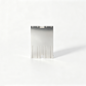


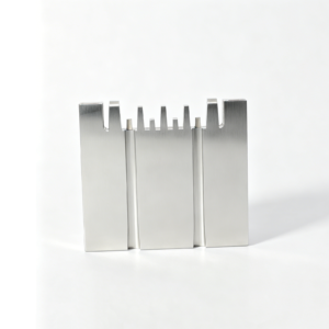


Blanking Die Components, Planned From the Drawing
A disciplined manufacturing workflow helps align process choices, critical dimensions, inspection expectations, and revision details before production begins.
DFM Before Quotation
We review drawing requirements, datum strategy, tool access, and manufacturability questions before confirming a production route.
Integrated Process Planning
CNC machining, EDM, precision grinding, fitting, and inspection are planned as connected steps for each drawing-based die part.
Critical Dimensions First
Critical-to-quality dimensions, surface priorities, and tolerance relationships are identified so machining and inspection focus on functional features.
Inspection Plan Alignment
Reporting needs and inspection methods are discussed against the order, helping documentation match the agreed verification plan.
Visible Revision Control
Drawing revisions and project changes remain visible throughout coordination, reducing ambiguity between approved requirements and manufactured components.
Technical Communication
Share drawings, models, material requirements, quantities, delivery targets, and mating context for a more informed manufacturing discussion.
Blanking Die Component Families
Drawing-driven components organized by the functional challenges that govern fit, wear, alignment, release, and inspection.

CNC Machining Services
Precision CNC machining services for drawing-based die parts, combining milling, turning, EDM, grinding, and inspection according to feature geometry, material condition, critical dimensions, and required documentation.
Upload a Drawing
CNC Milling
Custom CNC milling services for plates, inserts, pockets, contours, and mounting features. Tool access, datum selection, clamping strategy, remaining stock, and finishing requirements should be reviewed before machining is committed.
Upload a Drawing
CNC Turning
Precision CNC turning services for round die details such as punches, bushings, sleeves, pins, and locating features. Quotations should define diameters, concentricity, shoulders, thread details, material condition, and inspection requirements.
Upload a Drawing
5-Axis Machining
5-axis CNC machining supports multi-face and contoured die components where fewer setups can help protect datum relationships. The feasible process route depends on tool reach, workholding, corner geometry, material, and critical tolerances.
Upload a Drawing
Swiss & Micro Machining
Swiss machining and micro machining support small, slender, and detail-intensive components where runout, handling, cutoff condition, and inspection method require early review. Provide the drawing, material, quantity, and functional mating context.
Upload a Drawing
Wire & Sinker EDM
Wire EDM and sinker EDM services address sharp internal profiles, narrow slots, hardened materials, complex cavities, and features with limited cutter access. Electrode strategy, wire path, corner conditions, recast considerations, and finishing allowance require definition.
Upload a Drawing
Precision Grinding
Precision surface and profile grinding supports controlled flatness, parallelism, profile accuracy, and final-size correction on die components. The process plan should account for material state, heat treatment, machining allowance, datum surfaces, and inspection method.
Upload a Drawing
Mold Core & Cavity Inserts
Precision mold core and cavity inserts are produced from customer drawings and models with attention to shutoff geometry, cooling or vent features where applicable, material requirements, heat-treatment sequence, EDM access, fitting, and inspection priorities.
Upload a Drawing
Ejector & Ejection Components
Ejector pins, sleeves, and ejection components are reviewed for fit, guide condition, bearing surfaces, stroke-related interfaces, and wear exposure. Submit the mating-component context, material or hardness requirements, dimensional priorities, and required reports.
Upload a Drawing
Core Pins, Guide & Locating Components
Core pins, guide pins, and locating components establish repeatable alignment and part-forming relationships. Production planning should confirm datum references, diameters, fit classes, engagement lengths, surface requirements, heat treatment, and inspection criteria.
Upload a Drawing
Slides, Lifters, Gates & Mold Accessories
Mold slides, lifters, gates, and accessories are made as configurable drawing-based components, not assumed catalog items. Functional motion, mating surfaces, wear zones, clearance, material condition, finishing, and fitting expectations should be defined before production.
Upload a Drawing
Connector Mold Components
Precision connector mold components support fine-pitch, alignment-sensitive tooling details such as inserts, cores, pins, and locating elements. Reviews focus on critical geometry, small-feature accessibility, EDM or grinding needs, material condition, and measurement strategy.
Upload a Drawing
Stamping Die Components
Precision stamping die components include punches, die inserts, wear plates, guide elements, and custom forming details. Material selection, heat-treatment sequence, edge condition, clearance-related geometry, grinding stock, and inspection requirements guide the route.
Upload a Drawing
Injection Mold Components, MIM, CIM & Overmolding Tooling
Injection, MIM, CIM, and overmolding tooling components are evaluated within verified production scope. Drawings should identify resin or feedstock context, molding interfaces, critical shutoffs, cavity or core details, surface requirements, and fitting expectations.
Upload a Drawing
Machining Materials
CNC machining materials are selected against drawing requirements, mechanical function, heat-treatment route, corrosion exposure, wear demands, and manufacturability. Specify the required material grade, condition, substitute restrictions, and any material-certificate requirement in the RFQ.
Upload a Drawing
Surface Finishes & Heat Treatment
Surface finishing and heat treatment are planned around function rather than assumed as generic add-ons. Define hardness, treatment sequence, coating or finish requirement, masking needs, surface-critical areas, dimensional effects, and applicable verification documentation.
Upload a Drawing
Quality, Metrology & Documentation
Precision inspection, metrology, and quality documentation are aligned to the order’s critical dimensions and inspection plan. Provide drawing revision, datums, reporting format, sampling expectations, material records, and any application-specific traceability requirements.
Upload a Drawing
Prototyping & Low-Volume Production
Rapid prototyping and low-volume manufacturing support drawing-driven validation, tooling development, replacement details, and controlled production needs. RFQs should state quantity, target date, material, revision status, critical dimensions, surface requirements, and inspection deliverables.
Upload a DrawingMaterials for Blanking Die Components

Tool Steel
A hard, wear-resistant choice for punches, die blocks, and cutting inserts. Grade selection, supplied condition, heat-treatment sequence, and grinding allowance should be defined so machining and final edge performance align.

High-Speed Steel
Used where cutting-edge wear resistance and hot hardness matter, including demanding punch applications. Its harder machining response requires a planned route for pre-machining, heat treatment, EDM where needed, and finish grinding.

Alloy Steel
A versatile family for die plates, retainers, guides, and structural tooling parts. Machinability and toughness vary by grade, so the drawing should identify strength targets, heat treatment, critical bores, and datum relationships.

Stainless Steel
Often specified for components exposed to moisture, corrosion-sensitive environments, or particular material-handling conditions. Grade, hardness condition, and surface requirement affect machining behavior, EDM strategy, and the final inspection plan.

Carbide Materials
Selected for high-wear cutting elements, small punches, and inserts where stiffness and abrasion resistance are priorities. Brittle material behavior demands careful geometry review, suitable grinding methods, edge-condition requirements, and handling controls.
Machining Processes for Blanking Die Components

CNC Milling
CNC milling creates die plates, retainers, blocks and formed features with planned tool access. Process planning considers datums, stock allowance and later EDM or grinding operations to protect functional geometry.

CNC Turning
CNC turning supports rotational blanking die components such as punches, pins, bushings and locating elements. Diameter relationships, concentric features and material condition are reviewed against the drawing before machining begins.

Wire EDM
Wire EDM produces precise through profiles, narrow slots and hardened features where conventional cutting access is limited. The wire path, start-hole location, corner condition and finishing allowance are planned around functional requirements.

Sinker EDM
Sinker EDM forms deep cavities, internal details and sharp-feature geometries that require an electrode strategy. Electrode wear, finish expectations and machining allowance are considered before final dimensions are completed.


Fitting and Inspection
Fitting and inspection verify mating relationships, critical dimensions and specified surface requirements before delivery. The inspection method and documentation are aligned with the order, drawing revision and agreed quality plan.
Accessories and Supporting Die Hardware

Guide Elements
Guide pins, bushings, and locating sleeves can be machined or selected around the die-set interface. Define fit, datum relationship, lubrication expectations, and replacement requirements during drawing review.

Precision Fasteners
Shoulder screws, dowel pins, and mounting fasteners support repeatable plate location and service access. Provide thread standards, engagement, head clearance, torque considerations, and any material or surface requirements.

Die Springs
Springs and related retention features can be incorporated where stripping, return force, or controlled travel is required. Confirm load range, working stroke, installation space, and replacement accessibility before production.

Locating Features
Custom stops, gauges, keys, and alignment blocks help establish strip position and assembly reference. Their dimensions should be coordinated with functional datums, tool access, wear points, and the mating die structure.

Ejection Parts
Ejector pins, knock-out elements, and return components can be produced for the specified die architecture. Critical details include running fit, stroke, hardened contact areas, clearance paths, and inspection points.

Identification Marks
Part numbers, revision marks, orientation identifiers, and controlled engraving support assembly and traceability. Specify marking content, location, depth, readability, and whether the feature must remain visible after fitting.
About SUUXIANG Blanking Die Components
SUUXIANG is the sole public-facing precision-manufacturing brand of Dongguan SuuXiang Precision Mold Co., Ltd., established in 2010 and based in Chang’an Town, Dongguan, Guangdong, China. Founder and legal representative XiaoCheng Huang leads a company that helps international engineering and sourcing teams translate drawings and specifications into inspected custom CNC parts, precision mold components, connector tooling, and blanking die components.
Our work is planned around the actual part requirement: CNC milling and turning, multi-axis machining, EDM, precision grinding, fitting, and inspection are combined only where the drawing, material, datum scheme, and surface requirements call for them. Before quotation and production, we review critical dimensions, machining access, EDM strategy, grinding allowance, and inspection expectations.
What distinguishes SUUXIANG is disciplined drawing-to-inspection coordination. We keep revision details, manufacturing decisions, and delivery information visible throughout the project, so procurement and quality teams can align requirements before parts are released. Submit your drawing, material, quantity, quality needs, and target delivery date for a focused manufacturing review.

Core Capabilities Behind Blanking Die Components
Drawing Review Before Commitment
SUUXIANG reviews the 2D drawing, 3D model, material, quantity, datums, critical dimensions, surface requirements and application context before confirming a process route. This exposes machining-access, tolerance-stack and heat-treatment questions early, when design or specification changes remain manageable.
- Identify critical-to-quality dimensions and functional datums
- Confirm material, heat treatment and surface requirements
- Review tool access, internal features and setup strategy
- Define inspection and documentation needs before production

CNC and EDM Strategy
Blanking die components often combine prismatic machining, small features and hardened or difficult-to-reach details. Process planning considers CNC milling or turning first, then wire EDM or sinker EDM where the geometry, corner condition, access path or finishing requirement calls for it.
- Match machining sequence to geometry and datum control
- Assess wire path and start-hole requirements
- Plan electrodes when sinker EDM is appropriate
- Keep EDM, machining and finishing requirements visible

Grinding and Fitting Allowance
Grinding stock and fitting allowance should be defined from the part’s mating function, heat-treatment sequence and final tolerance requirements. SUUXIANG uses the supplied drawing and assembly context to discuss where stock must remain for finishing, rather than treating every dimension as a single-operation machining target.
- Review post-heat-treatment finishing requirements
- Preserve appropriate stock for precision grinding
- Clarify mating faces, sliding areas and clearance conditions
- Flag dimensions needing assembly-level confirmation

Inspection and Revision Control
Inspection planning follows the agreed critical dimensions, datums and reporting expectations for the order. Revision-controlled drawings, material requirements and inspection evidence should travel together so buyers can compare delivered blanking die components with the approved manufacturing and quality requirements.
- Align measurement methods with critical features
- Confirm requested reports before release to production
- Maintain visibility of drawing and revision status
- Match final documentation to the verified inspection plan

Why Choose SUUXIANG for Blanking Die Components
Compare a drawing-led manufacturing workflow with a typical generic supplier approach.
← Swipe left or right to view →
Blanking Die Components: From Drawing Review to Delivery
A drawing-driven route that keeps manufacturability, critical dimensions, process decisions, inspection requirements, and delivery coordination visible before production proceeds.
RFQ and Drawing Review
Share 2D drawings, models, material, quantity, application, quality requirements, and delivery target so the team can identify missing inputs and clarify scope.
DFM and Process Planning
Review critical dimensions, datums, tolerances, tool access, heat-treatment sequence, machining allowance, electrode strategy, wire path, and the inspection approach before quotation.
Material and Route Confirmation
Confirm the specified material and approved manufacturing route, then align revision-controlled requirements for CNC machining, EDM, grinding, fitting, and documentation.
Machining and EDM Execution
Produce blanking die components through the planned combination of CNC milling, turning, multi-axis machining, wire EDM, sinker EDM, and controlled in-process checks.
Grinding, Fitting, Inspection
Complete grinding and fitting as required, verify defined critical dimensions using the planned inspection method, and prepare records that match the order requirements.
Packing and Shipping Coordination
Review final parts, documentation, packing needs, and delivery details before coordinating shipment information with the customer under the approved project revision.
How to Source Blanking Die Components with SUUXIANG
A drawing-led path from technical review through coordinated, documented delivery.
Submit Your Drawing Package
Send 2D drawings, 3D models, material and heat-treatment requirements, quantity, target date, and inspection needs. Identify critical dimensions, datums, surface priorities, and mating-component context.
Review DFM and Quote
Review the proposed machining, EDM, grinding, heat-treatment, and inspection approach. Confirm quotation scope, revision status, sampling expectations, and open manufacturability questions before release.
Approve Production Details
Align on the approved drawing revision, critical-to-quality features, datum strategy, process sequence, inspection method, and delivery requirements before blanking die components enter production.
Receive Documented Delivery
Receive coordinated delivery with documentation matched to the agreed order and verified inspection plan, keeping revision information and quality expectations visible through final handoff.
Blanking Die Components Quality Documentation Review
Customer Feedback Publication Policy
Customer testimonials are published only after approval and verification of the applicable drawing review, manufacturing scope, inspection plan, and project outcome.
Project outcomes are published only with approved attribution, application context, and support for any dimensional, delivery, or inspection statement.
Published feedback will describe applicable component requirements and exchanged evidence without disclosing confidential drawings or unsupported performance figures.
Blanking Die Components FAQ
Practical guidance for preparing a drawing-based RFQ, confirming inspection needs, and managing revisions through delivery.
What is the minimum order quantity for blanking die components?
What information do you need to quote blanking die components?
Can you provide samples before a production order for blanking die components?
How should I plan lead time for a custom die-component order?
Can SUUXIANG provide inspection reports with an order?
How are drawing revisions controlled during production?
How do you handle IP and confidential drawings?
How are payment and international shipping coordinated?
Complete Buyer’s Guide to blanking die components
Use this decision framework to specify components, compare manufacturing partners, control tooling risk, and avoid costly fit, wear, quality, and lead-time mistakes before approving a drawing-based order.
1. What Are blanking die components?
One blanking die is a press tool that shears a finished blank from sheet stock; the blank is the stamped workpiece, not a die component. In a typical stroke, the upper punch descends through the material into the lower die opening, separating the contour by controlled clearance.
Three functional groups make that cut repeatable: a stripper holds and releases stock, guide pillars and bushings align upper and lower members, and backing plates, retainers, screws, dowels, and support blocks transmit load and hold cutting elements. The press stroke therefore depends on the whole die set, not only the punch and die.
Two sourcing categories should be separated on the RFQ. Standard items may include guide elements, fasteners, springs, and selected retainers; drawing-specific items usually include punches, die inserts, stripper plates, plates, pockets, and fitted supports. Specify the assembly drawing, part drawings, material and heat-treatment requirements, datums, critical dimensions, mating relationships, and inspection needs so SUUXIANG can review what must be manufactured versus purchased.
2. Evolution of blanking die components
Three design shifts changed blanking die components: manually fitted press tools gave way to standardized die sets, then to interchangeable punches, dies, guides, and retainers. Common interfaces made replacement practical without rebuilding every supporting plate, improving maintainability when wear concentrated at cutting edges.
Two digitally controlled processes—CNC machining and EDM—made complex profiles, hardened-tool details, and repeatable mating features easier to manufacture from controlled geometry. CAD-based assemblies also let buyers review datums, clearances, fastener locations, and service access before components were released.
One inspection plan now links the drawing revision to critical dimensions, measurement method, and acceptance record. For buyers, that discipline supports repeatability between replacement orders, quicker fault isolation, tighter documentation, and less press downtime caused by uncertain fit or obsolete part data.
3. Types of blanking die components
A die BOM is easier to review when every item is assigned by its load path and interface. Map each component to cutting, guidance, pressure, support, feed, or scrap control before releasing machining drawings.
| Category | Primary Interface | Typical Failure |
|---|---|---|
| Cutting | Punch to die opening | Burr or breakage |
| Guidance | Posts to bushings | Misalignment |
| Pressure | Stripper to stock | Material lift |
| Support | Insert to retainer | Insert movement |
| Feed | Pilot to strip | Feature shift |
| Scrap | Die opening to chute | Die jam |
Cutting Elements
Punches, die blocks, and inserts shear the profile. Variants include solid, sectional, and replaceable inserts; worn edges cause burrs or fractured tools.
Guidance Elements
Guide posts and bushings align upper and lower die halves. Ball-bearing or plain variants interface with plates; lost alignment damages cutting edges.
Stripping And Pressure Elements
Stripper plates hold stock during punch withdrawal. Fixed or spring-loaded designs contact punches and stock; poor pressure can pull material or bend punches.
Support And Retention Elements

Backer plates, retainers, screws, and dowels carry and locate inserts. Their interfaces preserve stack rigidity; inadequate retention permits insert movement.
Feed And Stock-Control Elements
Pilots, guides, stops, and lifters position strip stock. Adjustable stops and fixed guides interface with feed direction; errors shift features between stations.
Scrap-Handling Elements
Scrap chutes, slugs, and evacuation openings clear offal. Interfaces below the die block need clearance; blocked discharge can jam or damage the die.
4. Materials for blanking die components
Material selection starts with duty: cutting edges need wear resistance, guides need stable sliding behavior, and structural plates need stiffness and economical replacement. Confirm the stock, thickness, annual volume, press load, lubrication, and storage environment before releasing blanking die components.
| Component Duty | Material Family | Primary Trade-Off | Service Focus |
|---|---|---|---|
| Punches and dies | Tool steel | Wear versus toughness | Resharpening |
| Guides | Bearing or alloy steel | Sliding versus corrosion | Replaceable fit |
| Holders and backing | Plate steel | Stiffness versus machining cost | Support |
| Severe-wear inserts | Carbide | Wear versus brittleness | Supported replacement |
Match Steel To Duty
Punches and die inserts commonly use heat-treatable tool steel when edge wear and compressive loading govern.
Guide pins and bushes commonly use bearing or alloy steel where sliding, fit retention, and replacement service matter.
Plan Heat Treatment
Heat treatment should follow the machining route, with grinding stock and EDM finishing allowance defined on the drawing.
Coatings can reduce adhesive wear, but they do not correct poor clearance, inadequate toughness, or unstable support.
Specify Service Conditions
Carbide merits review for severe abrasive wear or long production runs, but its lower toughness requires supported geometry.
Corrosion exposure, press speed, stripping force, and maintenance access should remain visible in the RFQ.
5. Custom blanking die components options
2D drawings and 3D models should define the functional interfaces, datums, critical dimensions, and revision. Custom blanking die components are most economical when each feature is tied to press operation, strip material, and mating-part function.
| Customization | Specify When Needed | Avoid |
|---|---|---|
| Working edge | Cut quality or wear depends on it | Generic clearance values |
| Mounting features | Assembly datum requires them | Extra tight hole tolerances |
| Markings | Matched sets need traceability | Decorative surface finishing |
Working-Edge Geometry
Corner radii, relief angles, and clearance must be reviewed for each design; sheet thickness, grade, burr direction, and press conditions determine the appropriate values. Relief behind a cutting land can help prevent blanks from stacking in the die.
Drawing And Operating Inputs
1 complete RFQ package includes the released 2D drawing, 3D model, material and heat-treatment callouts, quantity, and revision history. Add strip thickness and grade, press tonnage, strokes per minute, required edge condition, mating interfaces, inspection requirements, and target date.
Specify Function First
0 unnecessary tight tolerances on non-locating faces increase grinding, inspection, and delivery risk without improving die performance. Limit polished finishes, coatings, keyways, mounting holes, markings, and matched-set identification to features needed for wear, assembly, maintenance, traceability, or error-proofing.
6. Quality elements in blanking die components
Two coupled conditions—edge condition and punch-to-die clearance—largely determine burnish, fracture zone, and burr. Verify them with the intended stock, press direction, and die-set datum scheme.
Cutting Edges And Clearance
0.005 mm edge chipping can become a burr or local overload point. Call out cutting-edge break, clearance per side, relief, and allowable burr direction.
100% visual edge inspection should record chips, wire-EDM witness condition, and burrs before assembly.
- Specify clearance by material and thickness
- Define edge-break limit and burr side
- Request microscope photos for critical profiles
Guidance And Stack-Up
Two guide pillars establish repeatable upper-to-lower die alignment. Control guide fit, punch-to-die concentricity, plate flatness, dowel locations, and assembled shut-height stack-up.
A datum-based assembly report helps prevent press instability, uneven wear, and replacement parts that require hand fitting.
- Datum-tag guide bores and dowel holes
- State flatness on mounting faces
- Measure concentricity from functional datums
Hardness And Replacement Evidence
3 records should accompany critical replacement components: material certificate, heat-treatment record, and dimensional inspection report. Specify hardness range, effective hardened depth where applicable, surface finish, revision, and part identification.
1 first-article assembly check should confirm fit with mating components. SUUXIANG can align inspection evidence to the approved drawing and revision plan before production.
- Request measured critical dimensions and datums
- Require revision-controlled inspection records
- Retain mating-part identifiers for interchangeability
7. Choosing a blanking die components manufacturer
1. Select suppliers against an agreed evidence pack, not a capability list. Drawing review, process planning, inspection, traceability, and controlled communication should be scored before price is compared.
| Evaluation Area | Evidence To Request | Decision Risk |
|---|---|---|
| Drawing review | DFM and CTQ response | Unmachinable features |
| Measurement | Method and inspection plan | Unverified fit |
| Change control | Revision log and approval | Obsolete geometry |
| Lead-time plan | Process dependencies and milestones | Late tool build |
Verify Technical Readiness
1. Ask for a drawing-review response identifying CTQ dimensions, datums, tool access, grinding stock, and DFM risks.
2. Confirm the proposed CNC, wire EDM, sinker EDM, grinding, fitting, heat-treatment sequence, and measurement method match each feature.
Match Questions To Order Type
1. Prototype orders require feedback on manufacturability, revision speed, sample inspection, and realistic lead-time dependencies.
2. Replacement parts require confirmed interfaces, wear history, material identity, and dimensional comparison with the mating tool.
3. Production-tooling orders require repeatability planning, sample approval criteria, change control, and protective packaging.
Control Evidence And Changes
1. Require material traceability, heat-treatment records where specified, inspection results, and a sample-approval route before release.
2. Define revision ownership, approval checkpoints, shipment labeling, packaging protection, and escalation contacts in the purchase order.
8. Common blanking die components mistakes
One incomplete data package can force assumptions into a die component that controls fit, clearance, or maintenance. Before PO release, convert every assumption into a drawing note, model reference, or agreed inspection requirement.
Incomplete Interface Data
Two mating dimensions—a punch diameter and die-opening datum—can determine whether a replacement fits. Missing strip layout, clearance, or grain direction can cause burrs, interference, or premature wear; provide mating-part models, stock specification, and datum scheme.
Unclear Material Requirements
One low-price steel choice may reduce initial cost while increasing chipping, distortion, or rework. State material grade, hardness range, heat-treatment sequence, coating requirement, and the surface or edge condition each requirement protects.
Unverified Replacement Strategy
First-article approval is the practical checkpoint for proving dimensions, assembly fit, and inspection method before repeat manufacture. Assuming interchangeability without controlled revision data risks mixed parts; approve a first article, freeze revision identifiers, and define spare quantities with the PO.
9. Steps to launch a die-component order
A controlled launch turns a drawing package into a traceable production record. For blanking die components, align engineering, sourcing, and quality before any machining release.
Capture The Released Package
At RFQ, provide the released 2D drawing, 3D model when available, quantity, material, heat treatment, surface requirements, application context, and target date.
Each file needs a revision identifier. Engineering should identify CTQ dimensions, datums, mating interfaces, and required inspection reports; the buyer signs off that the package is complete.
Close DFM And Commercial Decisions
During drawing review, resolve tool access, EDM or wire paths, grinding stock, heat-treatment sequence, and inspection method. Record every accepted deviation or open question in writing.
Before order release, compare quotations on scope rather than unit price alone. Procurement confirms quantity and delivery terms, while engineering and quality approve the documented process route and acceptance criteria.
Approve, Build, And Preserve Records
For first articles, approve sample or FAI results against the released revision before production proceeds. Quality review should cover critical dimensions, material evidence when specified, and report completeness.
At shipment, match packing labels, quantities, inspection documents, and revision to the purchase order. Keep the drawing, quote, change record, inspection plan, and approved sample results under one component record for reorders.
10. Blanking die components pricing and cost
2D drawings and 3D models are the basis for a firm quote because they reveal datum relationships, tool access, and critical dimensions. Published unit prices would hide the setup, process-route, and inspection variables that govern blanking die components.
3 inputs—annual quantity, required delivery date, and inspection evidence—often change the commercial route as much as geometry. Send the latest revision, material and heat-treatment requirements, and any mating-part context for a reviewable quotation.
| Cost driver | Cost impact | Lead-time impact | Buyer action |
|---|---|---|---|
| Part size and geometry | Higher with deep pockets, thin sections, or difficult access | More machining setups | Provide section views and 3D model |
| Material and heat treatment | Higher for specified tool steel and controlled treatment | Adds external process sequencing | State grade, hardness, and sequence |
| EDM, grinding, tolerance | Higher for electrodes, wire paths, tight fits, and grinding stock | Adds specialist operations | Mark CTQ dimensions and datums |
| Coating and inspection | Higher for specified coating or documented measurement | Adds supplier and reporting time | Define coating, report, and sampling needs |
| Quantity and urgency | Setup spreads across repeat quantities; expedited work may require rescheduling | Depends on capacity and approval timing | Give forecast, lot size, and target date |
Upload Your Drawing for Blanking Die Components Review
Include material, quantity, critical dimensions, inspection expectations, and target delivery date so SUUXIANG can prepare a reviewable RFQ.