
Custom Ejector Pins for Precision Tooling
Move from drawing review and DFM to inspected ejector pins with controlled CNC machining, EDM, grinding, and revision traceability.
Representative Precision Tooling Components





Request a Quote for Custom Ejector Pins


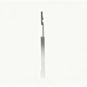

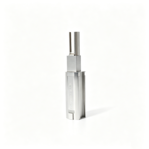

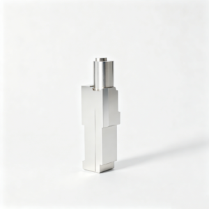


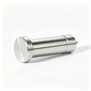
Ejector Pins Built From Drawings
Practical engineering review and coordinated manufacturing planning for custom mold ejection components.
Drawing-Led Review
We assess drawings, models, material requirements, application context and quality expectations before defining a workable ejector pin manufacturing route.
DFM Before Commitment
Early DFM discussion addresses tool access, datum strategy, heat-treatment sequence and potential ejection risks before quotation or production commitments.
CNC, EDM and Grinding
Process planning coordinates CNC machining, EDM and precision grinding when geometry, hardened features or finish requirements call for each method.
Critical Dimension Planning
Critical dimensions, surface priorities and inspection methods are identified with the customer to support focused measurement planning and clear acceptance criteria.
Revision Visibility
Drawing revisions, inspection expectations and delivery information remain visible through project coordination, helping teams maintain traceable communication from review to shipment.
Precision Tooling Component Families
Drawing-driven machining, EDM, grinding and inspection for configurable tooling components and custom parts.

CNC Machining Services
Precision CNC machining services begin with drawing review, material requirements, critical dimensions and inspection needs. Process planning combines milling, turning, EDM, grinding and fitting as the part geometry, tolerance stack and delivery requirements require.
Upload a Drawing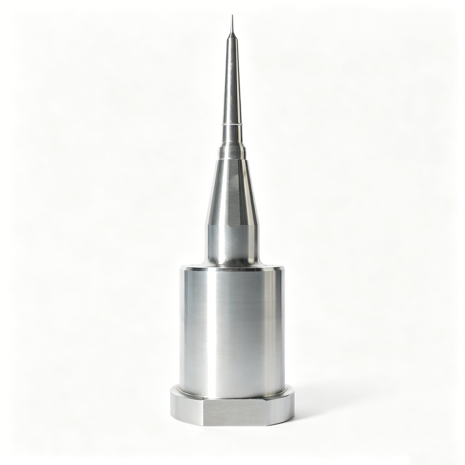
CNC Milling
Custom CNC milling services support prismatic parts, pockets, contours, locating features and mold-component geometry. Tool access, datum selection, machining allowance and surface requirements should be reviewed before production commitments are made.
Upload a Drawing
CNC Turning
Precision CNC turning services support rotational components such as pins, sleeves, bushings, shafts and stepped profiles. Concentricity, runout, thread requirements, material condition and downstream grinding or heat-treatment sequence require clear definition.
Upload a Drawing
5-Axis Machining
5-axis CNC machining helps access compound angles, deep features and complex mold-component geometry with fewer workholding changes where practical. Feasibility depends on tool reach, datum control, material condition, tolerance requirements and inspection access.
Upload a Drawing
Swiss & Micro Machining
Swiss machining and micro machining support small, slender and detailed components where handling, concentricity and feature access matter. Drawings should define critical diameters, lengths, threads, edge conditions, material and inspection expectations.
Upload a Drawing
Wire & Sinker EDM
Wire EDM and sinker EDM services address hardened material, narrow slots, intricate profiles, sharp internal geometry and features unsuitable for conventional cutting. The process review should define wire path or electrode strategy, flushing access, recast-layer expectations and finishing requirements.
Upload a Drawing
Precision Grinding
Precision surface and profile grinding establishes controlled flatness, parallelism, profile accuracy and final-size relationships after machining or heat treatment. Grinding stock, datum sequence, wheel access and measurement method should be confirmed during drawing review.
Upload a Drawing
Mold Core & Cavity Inserts
Precision mold core and cavity inserts are configured from the mold design, resin or application context, material specification and critical molded features. CNC, EDM, grinding and fitting routes are selected around geometry, heat-treatment sequence, surface requirements and inspection plan.
Upload a Drawing
Ejector & Ejection Components
Ejector pins, sleeves and ejection components require attention to diameter control, straightness, bearing surfaces, clearance relationships and wear conditions. Provide mating-part context, material and heat-treatment requirements, surface priorities and critical dimensions with the RFQ.
Upload a Drawing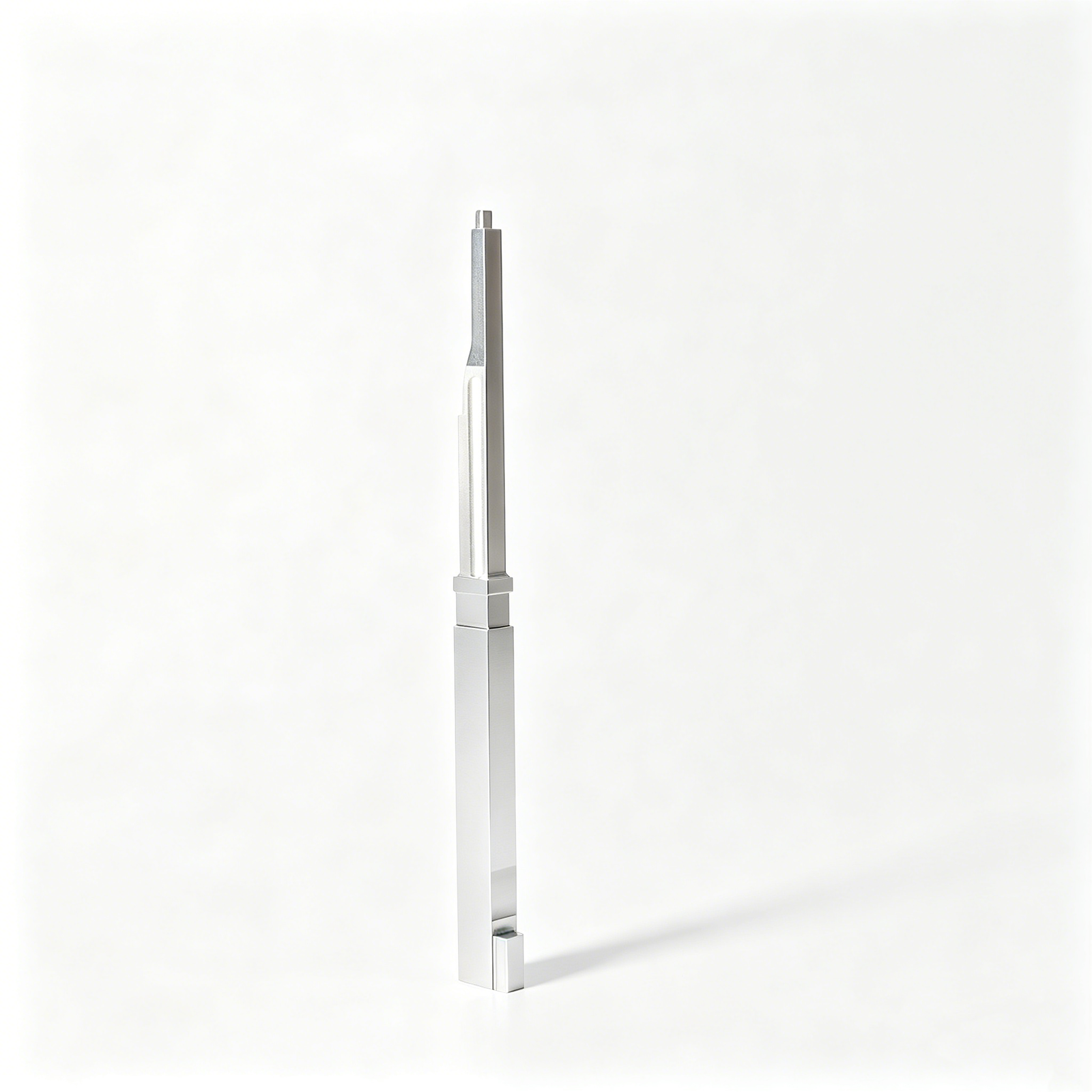
Core Pins, Guide & Locating Components
Core pins, guide pins and locating components are produced against defined datums, fit relationships and mating geometry. Buyers should identify critical diameters, shoulder locations, engagement lengths, hardness requirements, finish needs and the inspection evidence required.
Upload a Drawing
Slides, Lifters, Gates & Mold Accessories
Mold slides, lifters, gates and accessories are drawing-driven components whose performance depends on motion, clearance, wear surfaces and interface geometry. Review travel, mating parts, lubrication considerations, material condition and fitting expectations before release.
Upload a Drawing
Connector Mold Components
Precision connector mold components support detailed cavity, core, pin and alignment features used in connector tooling. Requirements should clarify pitch-critical dimensions, pin geometry, material, heat treatment, EDM needs, surface condition and inspection strategy.
Upload a Drawing
Stamping Die Components
Precision stamping die components are evaluated around strip material, forming or cutting function, clearance relationships, wear zones and assembly datums. Manufacturing routes may combine CNC machining, wire EDM, grinding and fitting according to the approved drawing package.
Upload a Drawing
Injection, MIM, CIM & Overmolding Tooling
Injection, MIM, CIM and overmolding tooling components are assessed within verified production scope. RFQs should include molded-material context, parting and gate requirements, insert or mating conditions, tooling material, surface needs and critical dimensions.
Upload a Drawing
Machining Materials
CNC machining materials are selected against the drawing, application, mechanical requirements, corrosion exposure, heat-treatment route and machinability. Confirm the required material grade, condition, traceability needs and any substitution restrictions before quotation.
Upload a Drawing
Surface Finishes & Heat Treatment
Surface finishing and heat treatment must be specified by function, not appearance alone. Define coating or treatment type, hardness or thickness requirements where applicable, masking needs, surface roughness priorities and dimensional changes that affect final fits.
Upload a Drawing
Quality, Metrology & Documentation
Precision inspection, metrology and quality documentation are planned around critical dimensions, datums, tolerances and agreed reporting requirements. Define measurement methods, sampling expectations, material records, revision status and any first-article or dimensional-report needs before production.
Upload a Drawing
Prototyping & Low-Volume Production
Rapid prototyping and low-volume manufacturing support drawing-based evaluation, fixture development, tooling iterations and controlled small-batch supply. Early review should align material, process route, critical dimensions, inspection scope, revision status and target delivery date.
Upload a DrawingMaterials for Custom Ejector Pins

H13 Tool Steel
A durable hot-work steel option for ejector pins exposed to repeated molding cycles and elevated thermal demand. Selection depends on hardness specification, diameter, heat-treatment sequence, surface condition, and required fit within the mold.

SKD61 Tool Steel
A commonly specified tool-steel family for precision ejection components where toughness and thermal stability matter. SUUXIANG reviews the drawing, mating features, finishing requirements, and application conditions before confirming material availability and processing.

High Speed Steel
A rigid, wear-oriented option for slender or demanding pin geometries where surface condition and dimensional retention require careful consideration. Final suitability depends on pin length, unsupported span, hardness requirement, and ejection load.

Stainless Tool Steel
A corrosion-conscious material route for tooling environments where moisture, resin behavior, storage conditions, or cleanliness requirements influence selection. Grade, heat treatment, finish, and critical dimensions should be defined in the RFQ and drawing.

Custom Specified Steel
For customer-designated grades, SUUXIANG evaluates the specified material alongside machining access, EDM needs, grinding stock, heat-treatment sequence, inspection method, and delivery requirements. Project acceptance remains subject to verified material and process evidence.
Precision Manufacturing Processes for Ejector Pins

CNC Milling
CNC milling establishes flats, shoulders, reliefs, head features, and accessible non-round geometry. Tool access, datum strategy, machining allowance, and later heat-treatment or grinding requirements are reviewed before the route is confirmed.

CNC Turning
CNC turning produces concentric diameters, stepped shafts, and other rotational features on ejector pins. The process plan considers stock condition, runout-sensitive features, allowance for finishing, and drawing-defined surface requirements.

Wire EDM
Wire EDM supports profiles, narrow slots, keyed details, and hardened features where conventional cutting access is limited. Wire path, start-hole location, corner requirements, and finishing passes are planned against the specified geometry.

Sinker EDM
Sinker EDM forms deep, detailed, or difficult-to-reach geometry when an electrode-based approach is appropriate. Electrode strategy, spark allowance, surface expectations, and any subsequent finishing operations are defined during drawing review.


Fitting and Inspection
Fitting and inspection verify mating relationships, critical dimensions, and drawing-defined documentation requirements before release. Measurement methods and reporting are aligned with the order, while revision status remains visible throughout project coordination.
Accessory and Assembly Features for Ejector Pins

Machined Pin Heads
Custom head diameters, thicknesses, reliefs and wrenching features can be machined to suit ejector plates and assembly access. Drawing review confirms bearing surfaces, transition radii and any heat-treatment sequence affecting final fit.

Retaining Features
Grooves, shoulders, flats and threaded retention details help locate ejector pins within the intended tooling assembly. Provide mating dimensions and datum references so retention geometry can be reviewed alongside strength, clearance and manufacturing access.

Guide Interfaces
Guide sleeves, bearing interfaces and mating bores may be specified where alignment, travel or wear behavior requires coordinated components. SUUXIANG reviews interface dimensions, fit intent, surface requirements and the inspection approach against the supplied assembly information.

Springs and Fasteners
Specified springs, screws and fastening interfaces can be coordinated with custom tooling parts when their sizes, loads and assembly relationships are documented. Compatibility depends on verified drawing requirements, purchased-component specifications and the approved project scope.

Identification Packaging
Part marking, revision identification, set separation and protective packaging can support receiving inspection and controlled assembly. Define marking location, traceability needs, quantity per set and handling constraints in the RFQ for review before production.
About SUUXIANG Ejector Pins Manufacturing
Dongguan SuuXiang Precision Mold Co., Ltd., established in 2010 in Chang’an Town, Dongguan, China, serves as SUUXIANG’s public-facing precision-manufacturing brand. We help international engineering and sourcing teams turn drawings, models, and specifications into inspected ejector pins, mold components, connector-tooling parts, and custom machined components.
Our drawing-driven workflow brings CNC milling and turning, multi-axis machining, EDM, precision grinding, fitting, and inspection into a controlled production route. Before quotation and production commitments, we review critical dimensions, datums, material and heat-treatment requirements, machining access, finishing needs, and inspection expectations.
What differentiates SUUXIANG is disciplined project communication around manufacturability, revision control, and traceable verification. Rather than treating ejector pins as an off-the-shelf promise, we align the process plan and inspection method to the approved drawing, order requirements, and application context before work begins.

Core Capabilities for Ejector Pins Projects
DFM and Datum Review
Before quotation, SUUXIANG reviews the drawing for critical dimensions, datum relationships, fit requirements, machining access and functional ejection surfaces. The discussion identifies where tolerances need a defined measurement strategy before process commitments are made.
- Provide 2D drawings and 3D models when available
- Identify critical diameters, lengths and shoulder locations
- Clarify mating-hole, clearance and assembly requirements
- Flag cosmetic or contact surfaces early

CNC Access for Fine Features
Ejector pins often combine long, slender geometry with shoulders, flats, reliefs or small functional details. SUUXIANG evaluates the appropriate CNC turning, milling, multi-axis, Swiss or micro-machining route against geometry, material condition and practical tool access.
- Review length-to-diameter stability considerations
- Confirm features requiring turning versus milling access
- Assess small diameters and secondary detail requirements
- Align material condition with the planned process route

EDM and Grinding Strategy
Where geometry, hardness or finish requirements make conventional cutting unsuitable, SUUXIANG plans EDM and grinding as controlled secondary operations. Electrode access, wire path, grinding stock and heat-treatment sequence should be resolved from the drawing before release.
- Define features that may require wire or sinker EDM
- Leave appropriate stock for precision grinding
- Review heat-treatment timing and distortion risk
- Specify surface and edge-condition priorities

Inspection and Revision Control
Inspection planning is tied to the order, drawing revision and agreed critical dimensions. SUUXIANG coordinates measurement methods, reporting expectations and delivery information so buyers can evaluate received ejector pins against the correct technical baseline.
- State inspection-report and traceability needs
- Mark critical-to-quality dimensions clearly
- Submit the current drawing revision with the RFQ
- Include quantity and target delivery requirements

Why Choose SUUXIANG for Ejector Pins
Compare the drawing review, process planning, inspection evidence, revision control, and delivery communication needed for custom ejector pins and related tooling parts.
← Swipe left or right to view →
Ejector Pins Manufacturing Workflow
A drawing-driven route from requirement review through inspection, packing and delivery coordination.
Review Drawings and Requirements
We review 2D drawings, 3D models, material, quantity, critical dimensions, datums, surface requirements, inspection needs, application context, and target delivery before quotation commitments.
Plan Material and Process
The team confirms a practical route for ejector pins, considering machining access, heat-treatment sequence, EDM needs, grinding allowance, tolerances, and revision-controlled production documentation.
Machine EDM and Prepare
CNC machining, turning, wire EDM, sinker EDM, and related operations are selected according to the approved geometry, feature access, electrode strategy, and process plan.
Grind Fit and Verify
Precision grinding and fitting address functional surfaces and interfaces, while in-process checks focus on critical dimensions, datum relationships, surface priorities, and approved drawing revisions.
Inspect Pack and Coordinate
Final inspection follows the order-specific plan. Verified parts are packed for protection, with inspection documentation, traceability information, and shipment coordination aligned to confirmed requirements.
Work With SUUXIANG on Ejector Pins
Align drawing details, production expectations and inspection evidence before manufacturing begins.
Submit Your Drawing Package
Provide a 2D drawing and, when available, 3D model, material, quantity, application context, critical dimensions, surface requirements and requested delivery date.
Review Scope and DFM
Align the process route, datum strategy, tolerance priorities, heat-treatment sequence, EDM or grinding needs, inspection expectations and revision status before quotation.
Confirm Production Requirements
Approve the quoted scope and clarify sampling, first-article, production, packing and reporting requirements so manufacturing proceeds against the correct controlled revision.
Coordinate Inspection and Delivery
Review inspection documentation against the agreed plan, confirm delivery details and keep revision, quality and shipment information visible through final order coordination.
Ejector Pins Quality Documentation

Customer Feedback Pending Verification
Reserved for approved customer feedback documenting how drawing-review clarification reduced revision cycles for a custom ejector pins project. Publish only after the customer confirms the measurable outcome, inspection-report scope, and permission to name the company.
Reserved for approved customer feedback on a drawing-based ejection-component order. The final quote should state a verified number, such as 2 clarified critical dimensions, and describe the agreed inspection documentation and revision-control outcome.
Reserved for approved customer feedback covering delivery coordination for custom ejector pins. Publish a verified project result, such as 1 consolidated delivery update per milestone, only when the customer approves the wording, result, and attribution.
Ejector Pins Manufacturing FAQ
Practical RFQ, manufacturing, inspection, and delivery questions for drawing-driven tooling components.
What information should I include in an ejector-pin RFQ?
Can SUUXIANG manufacture custom ejector pins from my drawing?
Which materials are commonly considered for ejector pins?
What tolerances can you hold on ejector pins?
How are custom ejector pins inspected before shipment?
What quantities can I order for ejector pins?
Can you provide samples before a larger production order?
How should I plan lead time, payment, and shipping for a custom order?
How does SUUXIANG protect drawings and project information?
The Complete Buyer’s Guide to Ejector Pins
Use this decision framework to specify ejector pins, compare materials and designs, assess drawing-driven suppliers, control cost, and avoid ejection failures, cosmetic defects, tolerance mismatches, and preventable tooling delays.
1. What Are Ejector Pins?
Ejector pins, also called knockout pins, are mold components that apply controlled force to release a cooled molded part from the core or cavity side that retains it. They are mounted in the mold’s ejector system and move with the ejector plate rather than acting as cutting tools.
In a typical injection-molding cycle, the mold opens after cooling, the ejector plate advances, and pin faces push on designed contact areas until the part clears the tool; the pins then retract before closing. This function is commonly assigned to the moving B-side, although reverse-ejection arrangements exist. Source: https://www.dme.net/ejector-pins.php
On the finished part, each pin contact can leave an ejector mark: a witness circle, pad, or local impression. Pin placement must distribute release load without distorting thin walls, overstressing localized areas, or placing marks on visible surfaces; poor contact geometry can also increase sticking, side loading, and wear in the ejection system. Source: https://www.protolabs.com/resources/design-tips/using-ejector-pins-properly-on-molded-parts
2. Ejector Pins: History and Evolution
Ejector pins evolved beyond simple mechanical knockouts as automated molding, interchangeable mold-base standards, and higher-cycle tooling raised requirements for diameter, straightness, head fit, clearance, and surface condition.
Material grade, heat-treatment sequence, hardness evidence, and any coating requirement should be defined for the application rather than inferred from a nominal diameter and length.
Geometry constraints often determine whether a nominally standard pin will work. Contoured, angled, stepped, keyed, or D-shaped ends may require grinding, EDM, and orientation control, so RFQs should state resin, operating conditions, cycle expectations, part-contact geometry, cosmetic limits, and inspection requirements.
3. Types of ejector pins
Eight common configurations divide ejection by contact geometry and function. Straight, shouldered, keyed, return, sprue-puller, sleeves, blades, and contoured pins are catalogued component families; selection remains drawing- and mold-layout-dependent (https://www.dme.net/ejector-pins.php).
| Type | Geometry And Use | Benefit / Limitation | Drawing Information |
|---|---|---|---|
| Straight | Constant round shank; general flat pads | Simple; point-load marks | Diameter, lengths, tip location |
| Shouldered | Larger head forms stop; ejector plate | Positive retention; needs counterbore | Head/shank diameters, shoulder position |
| Stepped | Multiple diameters; long slender reach | Stiffness; complex fit stack | Each diameter, transition radii |
| Blade | Flat rectangular working section; ribs | More contact; weak bending axis | Width, thickness, orientation |
| Sleeve | Hollow pin around core; bosses | Annular push; needs core clearance | ID, OD, keying, core relation |
| Return | Robust pin resets ejector plate | Reliable reset; not part ejection | Stroke, mounting, return sequence |
| Sprue-Puller | Profiled pin engages sprue | Controls runner release; mark risk | Tip profile, gate relationship |
| Contoured Or Keyed | Machined angled face with anti-rotation | Matches surface; orientation-sensitive | Surface profile, key/D-flat, datum |
Specify The Working End

A correct drawing locates the working face from mold datums, not only overall length.
Critical callouts include fit diameter, head geometry, stroke, surface finish, and permitted witness mark location.
Separate Pins From Components
Sleeves eject around cores; blades spread load across narrow ribs. They are related ejection components, not interchangeable round-pin substitutions.
Return pins reset ejector plates; sprue-pullers retain and release the runner.
Control Orientation
Contoured faces require an angular or surface definition. Keyed or D-shaped retention prevents rotation when face orientation matters.
Provide mating-part geometry and the allowable pad or recess condition.
4. Ejector pins Materials and Treatments
Material selection starts with the resin, mold temperature, corrosion exposure, ejection load, and planned production volume. Specify the treatment route with the pin geometry because surface condition and core toughness serve different failure risks.
| Option | Primary Fit | Key Caution |
|---|---|---|
| H13-type steel | Heat and toughness | Verify hardness and heat-treatment route |
| High-chromium cold-work steel | Abrasive resin wear | Check impact-fracture risk |
| Stainless tool steel | Corrosion exposure | Confirm grade and hardness target |
| Nitrided surface | Wear resistance | Control layer depth and growth |
Steel Family Trade-Offs
H13-type hot-work steel is commonly considered where thermal cycling and toughness matter; high-carbon, high-chromium cold-work grades favor abrasive wear but may trade toughness. Stainless tool steels merit review when resin, additives, storage, or processing conditions create corrosion risk.
Treatments And Drawing Data
Through-hardening sets bulk hardness; nitriding or other surface-hardening routes add a hard working layer while retaining a tougher core. Black oxide is a thin conversion finish, not a substitute for hardness or corrosion validation; polishing and coatings require defined roughness, adhesion, and dimensional allowance.
Request material grade or equivalent, target hardness and test method, treatment specification, surface-finish callout, coated-area definition, and post-treatment inspection records. Record actual hardness location, surface result, revision, and any treatment certificate against the order.
5. Custom Ejector Pin Specifications
A custom ejector pin is defined from the functional drawing, not a nominal catalog size. Specify the dimensions and inspection controls that govern fit, travel, contact, and replacement.
| Feature | Define On Drawing | Why It Matters |
|---|---|---|
| Body | Diameter and working length | Guide fit and travel |
| Head | Diameter and thickness | Retention in ejector plate |
| Tip | Profile, finish, edge condition | Part contact and marks |
| Orientation | Flat, keyway, or D-head | Anti-rotation control |
Define Functional Geometry

Diameter, overall length, head diameter and head thickness establish retention and guide fit. State working length, every step location and diameter, and the datum scheme used for measurement.
Specify The Working End

Tip geometry must match the part-contact surface: flat, radiused, tapered, contoured, or relieved. Call out edge break, surface finish, and any permitted witness mark where the pin contacts the molded part.
Control Rotation And Revisions
Flats, keyways, or D-shaped heads prevent a contoured or angled pin from rotating. Identify concentricity, straightness, critical tolerances, drawing revision, and whether mating components or a 3D model control the form.
- 2D drawing with revision and units
- 3D model and mating-part geometry
- Material, treatment, quantity, and delivery target
- Critical dimensions, finish, inspection report needs
6. Ejection Design and Quality Controls
Two linked decisions govern dependable ejection: where force enters the part and how the pin is guided. A drawing review should resolve both before steel is released.
Force Distribution
Multiple pins should share load through stiff, non-cosmetic pads or ribs; small contact areas can bruise hot parts.
Contoured or angled contact faces require anti-rotation control so the pin cannot change its bearing position.
Guidance And Return
Long, slender pins require guide support and a buckling review under worst-case release force. Clearance must permit motion without excessive side play, galling, or flash paths.
Matched ejector plates, guide elements, and positive return features should be checked through the full stroke.
Surface And Venting
Pin ends should land on pads, bosses, or hidden faces whenever appearance is critical. Deep features may use controlled pin clearance for venting, but the vent path must not mark or flash the part.
Lubrication needs a defined approved lubricant and maintenance interval, especially for sliding fits.
Inspection Evidence
First-article review should compare pin diameter, length, head geometry, datum-related locations, and end-face condition to the released drawing.
Order records should link material certificates, heat-treatment or hardness evidence when specified, dimensional results, revision level, and inspection disposition.
7. Choosing an Ejector Pins Manufacturer
Two suppliers can quote the same drawing yet use different review, process-control, and inspection disciplines. Select a manufacturer by the evidence it can provide before release, not by unit price alone.
| Evaluation Area | Evidence To Request | RFQ Question |
|---|---|---|
| Drawing review | CTQ and datum comments | What risks do you see? |
| Process control | Route and heat-treatment plan | When is final grinding done? |
| Inspection | Method and report sample | How are CTQs measured? |
| Traceability | Material and revision linkage | What records ship with parts? |
| Delivery | Schedule and packing plan | How are delays communicated? |
Drawing Review And Process Control
One drawing review should identify CTQ dimensions, datums, tolerances, tool access, EDM or grinding needs, heat-treatment sequence, and inspection method.
Two RFQ questions matter: Which dimensions need pre- and post-heat-treatment control? How will revision changes be acknowledged and released?
Material And Inspection Evidence
One reliable route links material documentation, machining records, heat-treatment requirements, and final inspection to the order and revision.
Two useful questions are: What certificate, hardness evidence, and inspection report can accompany the shipment? Which measuring method verifies each critical diameter, length, and surface requirement?
Delivery And Export Readiness
One prototype order should test communication speed, packing protection, labeling, export documentation, and realistic lead-time updates before low-volume release.
Two questions expose planning quality: What is the process-by-process schedule? What contingency applies if inspection finds a nonconformance?
8. Common Ejector-Pin Buying Mistakes
A 2D drawing that lists only diameter and length leaves the ejection system underspecified. Procurement errors usually surface later as sticking, pin marks, premature wear, rework, or unplanned tool downtime.
Specify Operating Conditions
Resin grade, filler content, mold temperature, cycle time, and expected strokes influence load, abrasion, and heat exposure. State these inputs before selecting steel, hardness, coating, or nitriding.
A nominal pin size alone cannot establish fit, straightness, surface finish, or working clearance. Define critical dimensions, datum references, allowable runout, and the inspection method.
Protect Part Appearance
Ejector contact on a Class-A or show surface can leave witness marks, gloss variation, or local deformation. Move contact to a hidden pad, rib, boss, or deliberately approved non-cosmetic area.
A contoured or angled pin face can rotate during repeated cycles. Specify a keyed, D-shaped, or equivalent anti-rotation feature where orientation affects contact.
Buy Against Acceptance Criteria
A purchase order without material, heat-treatment, finish, quantity, revision, and acceptance criteria cannot support a consistent receiving decision. Attach the controlled drawing and require inspection evidence matched to critical features.
A low unit price can omit grinding, treatment control, inspection, fitting, and replacement risk. Compare total cost against cycle life, scrap exposure, maintenance access, and delivery impact.
9. From Drawing to Production
One released RFQ should define the pin and the mold interface before machining begins. Assign engineering, quality, procurement, and program owners so technical decisions and commercial commitments remain traceable.
Build The Release Package
One drawing package should include 2D dimensions, 3D model when available, material, heat treatment, quantity, datums, and revision. Engineering owns geometry; program management confirms application context and target date.
- Identify critical dimensions and surface requirements
- State mold position, mating details, and ejection role
- List prototype, first-article, and replenishment quantities
Close DFM And Quotation
One drawing-review cycle should resolve machining access, grinding stock, EDM needs, inspection method, and exceptions before purchase order release. SUUXIANG can provide manufacturability feedback within its verified production scope; procurement aligns the quotation, delivery terms, and revision.
- Engineering approves technical clarifications
- Procurement approves commercial terms
- Quality approves inspection expectations
Approve And Control Production
First-article approval should compare the agreed inspection results with the released drawing and revision. Quality retains reports and nonconformance disposition; program management routes every change through written revision control before repeat orders.
- Define report format and sampling requirements
- Record approved revision and lot identification
- Plan reorder trigger and forecast quantity
10. Ejector Pins Pricing and Cost Drivers
A completed drawing package is the starting point for a defensible quote. Material grade, pin diameter, and finished length establish stock and machining time; stepped bodies, contoured tips, keyways, small diameters, or long slender sections increase setup, tool-access risk, and cycle time.
Pricing should distinguish a standard straight pin from a drawing-driven part. Tight diameter or concentricity tolerances, tip machining, heat treatment, finish, inspection reports, protective packaging, and expedited scheduling should be quoted as defined requirements, not assumed inclusions.
| Quantity tier | Cost-driver impact | Lead-time implication |
|---|---|---|
| 1–5 pieces | Setup, programming, first-article inspection, and individual packaging dominate. | Allow review and process planning before release. |
| 6–25 pieces | Setup cost is spread across more parts; special material or treatment remains significant. | Batch scheduling usually improves efficiency. |
| 26–100 pieces | Repeat machining and inspection can reduce unit cost when the drawing is unchanged. | Confirm material availability and inspection sampling. |
| Expedited order | Priority scheduling, split operations, and faster logistics may add cost. | Feasible timing depends on material, treatment, and capacity evidence. |
Upload Your Ejector Pins Drawing for Review
Include models, material and heat-treatment requirements, quantity, critical dimensions, inspection needs, and target delivery date for a disciplined manufacturing review.