
Flat Ejector Blades for Connector Molds, Built From Drawings
DFM-led review of critical dimensions, EDM strategy, grinding stock, and inspection requirements before production.
Representative Components for Connector-Mold Ejector-Blade Development





Related Configurable Components and Quotation


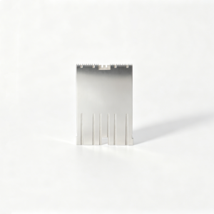


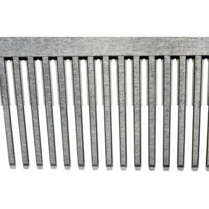


Why Connector Tooling Teams Specify SUUXIANG
Flat ejector blades for connector molds are planned from the drawing, critical datums, process access, inspection requirements, and controlled revisions.
Drawing Review First
We review blade geometry, critical dimensions, material requirements, application context, and quality expectations before quotation or production commitments.
Datum-Aware Planning
Process planning considers functional datums, tolerance stack, clamping approach, machining access, and where each feature can be controlled.
EDM and Grinding Coordination
CNC, wire EDM, sinker EDM, and grinding routes are selected around thin profiles, internal details, finishing needs, and allowance strategy.
Inspection Planned Early
Inspection methods are aligned with critical dimensions, reference surfaces, surface requirements, reporting needs, and the agreed verification plan.
Revision-Controlled Delivery
Drawing versions, manufacturing discussions, inspection documentation, and delivery details stay visible to support traceable connector tooling coordination.
RFQ-Ready Engineering Input
Send 2D drawings, 3D models, quantity, material, heat treatment, delivery targets, and mating-part context for a more useful review.
Connector Tooling and Precision Components
Explore configurable manufacturing routes for connector molds, critical tool components, and drawing-driven production requirements.

CNC Machining Services
Precision CNC machining and CNC machining services convert controlled drawings and models into custom machined parts through planned milling, turning, EDM, grinding, fitting, and inspection. Review focuses on critical dimensions, datums, material requirements, surface needs, and the evidence required before production is committed.
Upload a Drawing
CNC Milling
Custom CNC milling services support prismatic mold and tooling components where pocket geometry, datum relationships, tool access, and surface requirements must be evaluated together. The intended outcome is a machinable process route that protects critical features and leaves appropriate stock for subsequent operations.
Upload a Drawing
CNC Turning
Precision CNC turning services support rotational parts such as pins, sleeves, bushings, and locating features. Drawing review considers concentricity, runout, shoulders, thread details, material condition, and inspection references so functional diameters can be manufactured and verified against the required datums.
Upload a Drawing
5-Axis Machining
5-axis CNC machining helps address multi-face or contoured component geometry that would otherwise require repeated setups. Process planning evaluates access, clamping, tool reach, datum transfer, and finish requirements to reduce avoidable setup variation while maintaining inspectable critical features.
Upload a Drawing
Swiss & Micro Machining
Swiss machining and micro machining are considered for small, slender, or detail-intensive parts where handling, support, and feature sequence affect dimensional stability. Buyers should identify critical diameters, lengths, surface needs, material, quantity, and inspection expectations before route confirmation.
Upload a Drawing
Wire EDM Services & Sinker EDM Services
Wire EDM and sinker EDM services address hardened materials, narrow profiles, internal corners, fine details, and features beyond practical cutting-tool access. The route is selected around wire path or electrode strategy, flushing, EDM allowance, surface condition, and any downstream grinding or fitting requirements.
Upload a Drawing
Precision Grinding
Precision surface and profile grinding supports flatness, parallelism, profile control, and finished dimensions on hardened or precision tooling components. Planning accounts for heat-treatment condition, grinding stock, workholding, datum references, surface requirements, and the measurement method specified for acceptance.
Upload a Drawing
Mold Core & Cavity Inserts
Precision mold core and cavity inserts are produced as configurable components from customer drawings, models, material requirements, and molding context. Manufacturing planning considers cavity geometry, shutoff surfaces, cooling interfaces where applicable, heat treatment, EDM access, grinding allowances, fitting needs, and inspection priorities.
Upload a Drawing
Ejector & Ejection Components
Ejector pins, sleeves, and ejection components must operate reliably within the mold’s guidance and clearance conditions. Review should define diameters, straightness, hardness or material condition, mating relationships, surface requirements, and wear-sensitive areas before a manufacturing and inspection route is agreed.
Upload a Drawing
Core Pins, Guide & Locating Components
Core pins, guide pins, and locating components establish feature position and repeatability across mold assemblies. Their process route depends on functional diameter, length, concentricity, datum relationship, material and heat treatment, mating bores, and the inspection criteria needed to confirm assembly fit.
Upload a Drawing
Slides, Lifters, Gates & Mold Accessories
Mold slides, lifters, gates, and accessories are evaluated as working mold-system components rather than generic catalog items. Drawings should clarify motion interfaces, shutoff geometry, wear surfaces, clearances, material condition, fitting responsibilities, and any dimensional relationships that control mold operation.
Upload a Drawing
Connector Mold Components
Precision connector mold components support tooling used to form connector features where small pitches, alignment, mating geometry, and wear control can be consequential. SUUXIANG reviews critical dimensions, insert relationships, machining access, EDM or grinding needs, material, and inspection requirements before production planning.
Upload a Drawing
Stamping Die Components
Precision stamping die components are made from drawing-defined requirements for cutting, forming, guiding, and locating operations. Process planning considers material and hardness, profile complexity, clearances, wire-EDM path, grinding stock, surface condition, and the dimensional evidence required for component acceptance.
Upload a Drawing
Injection Mold Components, MIM, CIM & Overmolding Tooling
Injection, MIM, CIM, and overmolding tooling work is evaluated within verified production scope and application requirements. A useful review identifies molding material context, critical form features, insert relationships, tool access, heat-treatment sequence, surface requirements, and fitting or inspection responsibilities.
Upload a Drawing
Machining Materials
CNC machining materials are selected against function, machinability, heat-treatment needs, corrosion exposure, wear conditions, and drawing requirements. Buyers should specify the required grade or approved equivalent, material condition, traceability expectations, and any downstream treatment before quotation and production decisions.
Upload a Drawing
Surface Finishes & Heat Treatment
Surface finishing and heat treatment are planned around function, dimensional risk, corrosion resistance, wear, appearance, and mating behavior. Requirements should state the specified process, applicable standard or acceptance criteria, affected surfaces, masking needs, and whether final dimensions require grinding or inspection afterward.
Upload a Drawing
Quality, Metrology & Documentation
Precision inspection, metrology, and quality documentation are aligned to the drawing and agreed inspection plan. Define critical dimensions, datums, sampling or reporting needs, revision level, material or treatment evidence, and delivery documentation so the final records match the order requirements.
Upload a Drawing
Prototyping & Low-Volume Production
Rapid prototyping and low-volume manufacturing support drawing-driven evaluation, bridge demand, and controlled production quantities. Early review should identify revision maturity, critical features, material and treatment needs, target quantity, quality documentation, delivery date, and changes that could affect the selected process route.
Upload a DrawingMaterial Options for Flat Ejector Blades for Connector Molds

H13 Tool Steel
A durable hot-work steel option for blade components exposed to repeated molding cycles. It offers a balanced response to heat treatment and grinding, subject to confirmed hardness, geometry, and application conditions.

D2 Tool Steel
A wear-focused tool steel choice for flat ejector blades working against demanding guide or contact surfaces. Its high-carbide structure can support abrasion resistance, while machining allowance and heat-treatment sequence require drawing review.

A2 Tool Steel
An air-hardening tool steel considered where dimensional stability after heat treatment matters for narrow blade profiles. It suits precision tooling work when section size, hardness target, and final grinding requirements are defined.

Stainless Tool Steel
A corrosion-conscious material route for connector tooling used in humid handling or storage conditions. Grade selection depends on required hardness, magnetic response, surface finish, and compatibility with the mold environment.

Pre-Hardened Steel
A practical option for lower-risk blade components where the approved design does not require post-machining hardening. It can simplify machining flow, but wear demand, sliding contact, and critical dimensions must be evaluated first.
Processes for Flat Ejector Blades for Connector Molds

CNC Milling
CNC milling establishes blade profiles, head features, reliefs, and accessible reference surfaces from the approved drawing. Tool access, clamping strategy, and machining allowance are reviewed to support controlled downstream EDM or grinding.

Wire EDM
Wire EDM produces narrow profiles, internal clearances, and precision contours where conventional cutter access is limited. The programmed wire path is planned around required geometry, datum references, corner conditions, and finishing allowances.

Sinker EDM
Sinker EDM can form localized details, blind features, or difficult blade interfaces that require an electrode-based approach. Electrode strategy, discharge condition, and subsequent finishing needs are considered against the drawing and functional surfaces.


Fitting Review
Fitting review checks how the flat blade relates to its guide, retainer, ejector plate, and mating mold features. Assembly context helps identify interference risks, travel requirements, contact conditions, and drawing details needing clarification.

Final Inspection
Final inspection follows the agreed plan for critical dimensions, geometry, surface requirements, and documentation. Results are matched to the current revision so procurement and quality teams can review evidence appropriate to the order.
Accessory Features for Flat Ejector Blades for Connector Molds

Custom Head Profiles
Head shapes, bearing faces, and retention details can be machined to the approved drawing when blade installation, ejector-plate engagement, or available mold space requires a project-specific configuration.

Locating Features
Ground locating flats, shoulders, slots, or datum features can support repeatable orientation during assembly. Their dimensions and reference surfaces should be defined with the mating plate and tolerance stack.

Blade Identification Marks
Drawing-specified part numbers, revision marks, or position identifiers can help distinguish similar flat ejector blades during fitting, inspection, and maintenance while supporting controlled assembly documentation.

Mounting Hardware Interfaces
Clearance holes, threaded features, counterbores, or interface details may be incorporated where the approved tooling design calls for retained blade assemblies or related connector-mold hardware.

Mating Component Fits
Related guide, support, or retaining components can be reviewed as matched interfaces when supplied in the RFQ package. SUUXIANG evaluates datums, access, finishing sequence, and inspection requirements before production.
About SUUXIANG Precision Manufacturing
SUUXIANG is the sole public-facing brand of Dongguan SuuXiang Precision Mold Co., Ltd., established in 2010 and based in Chang’an Town, Dongguan, Guangdong, China. Founded by XiaoCheng Huang, the company helps international engineering, sourcing, and quality teams turn controlled drawings and specifications into inspected custom machined parts, precision mold components, connector tooling, and die components.
For flat ejector blades for connector molds, our practical scope combines CNC milling and turning, multi-axis machining, wire and sinker EDM, precision grinding, fitting, and inspection. Process planning begins with the drawing and application context, including critical dimensions, datum strategy, machining access, EDM needs, grinding allowance, and surface requirements.
What distinguishes SUUXIANG is a disciplined, drawing-driven workflow rather than an assumed catalog solution. Before quotation or production commitments, we review DFM, material and heat-treatment requirements, tolerance priorities, inspection methods, revision status, quantity, and delivery expectations so the agreed process route and documentation match the order.

Critical Capabilities for Flat Ejector Blades for Connector Molds
DFM and Datum Review
Before quotation, SUUXIANG reviews flat ejector blade drawings against the connector mold’s datum scheme, critical dimensions, blade envelope, mating features, and ejection function. The discussion identifies tolerance-stack risks and manufacturing questions that require resolution before production planning begins.
- Confirm functional datums and critical-to-quality dimensions
- Review blade width, thickness, head geometry, and clearance
- Identify mating-component and ejection-force considerations
- Record drawing revisions and open technical questions

CNC and EDM Route Planning
Flat ejector blades for connector molds often require more than a single machining operation. SUUXIANG plans the appropriate sequence of CNC machining, wire EDM, sinker EDM where justified, heat-treatment coordination, and finish operations based on geometry, access, material, and drawing requirements.
- Assess tool access for narrow profiles and internal details
- Select CNC, wire EDM, or sinker EDM by feature need
- Plan machining allowances around subsequent operations
- Align process sequence with specified material condition

Grinding and Fitting Strategy
Blade guidance, bearing faces, and working edges depend on a controlled finish strategy. SUUXIANG evaluates grinding stock, surface requirements, burr-sensitive edges, and fit relationships so the finished component can be checked against the drawing and its relevant mold-interface conditions.
- Define grinding stock before finish operations
- Protect functional edges from uncontrolled burrs
- Review fit surfaces and relevant clearance conditions
- Match surface expectations to the inspection approach

Inspection and Revision Records
Inspection planning follows the drawing and agreed project requirements, with attention to functional dimensions, datums, surface priorities, and reporting needs. SUUXIANG keeps revision information visible through production coordination so delivered flat ejector blades can be matched to the approved specification.
- Set inspection methods for critical dimensions
- Align reports with agreed order requirements
- Maintain traceable drawing revision references
- Flag inspection needs during RFQ review

Why Choose SUUXIANG for Flat Ejector Blades for Connector Molds
Compare a controlled drawing-review workflow with a typical quote-only sourcing approach.
← Swipe left or right to view →
Controlled Workflow for Flat Ejector Blades for Connector Molds
Each project follows a drawing-driven route, with process commitments confirmed against the applicable material, dimensions, inspection needs, and delivery requirements.
RFQ and Drawing Intake
Submit 2D drawings, models, material requirements, quantity, application context, target date, and reporting needs so the team can define a relevant review scope.
DFM and Critical Review
SUUXIANG reviews datums, critical dimensions, tolerance stack, machining access, heat-treatment sequence, ejection geometry, and inspection expectations before quotation or production commitments.
Process Route Planning
The planned route assigns suitable CNC machining, EDM, grinding, fitting, and intermediate controls based on blade geometry, required surfaces, and drawing-defined functional features.
Machining and Finish Control
Production follows the approved revision, with machining allowance, electrode or wire path, grinding stock, and finishing steps managed according to the project plan.
Inspection and Delivery Coordination
Finished components are checked against the agreed inspection plan, then packed and coordinated for delivery with revision visibility and order-matched documentation.
How to Source Flat Ejector Blades for Connector Molds
Move from drawing review to controlled production with requirements, critical dimensions, process decisions, and inspection expectations documented before release.
Submit Your Drawing Package
Provide 2D drawings, 3D models when available, material and heat-treatment requirements, quantity, target date, critical dimensions, surface priorities, and inspection documentation needs.
Review DFM and Quotation
Confirm datum strategy, machining access, EDM or grinding requirements, tolerance risks, revision status, inspection approach, and the proposed process route before quotation and production commitments.
Approve First-Article Evidence
Review samples or first-article results where applicable, including agreed critical-dimension measurements and revision details, before authorizing the next production stage for your connector tooling project.
Release Controlled Production
Proceed with the approved manufacturing plan through machining, EDM, grinding, fitting, and inspection, while keeping delivery coordination and final documentation aligned with the verified order requirements.
Quality Documentation Planning for Flat Ejector Blades for Connector Molds

Customer References for Flat Ejector Blades for Connector Molds
Approved customer feedback will be published only after the project scope, documented outcome, and customer authorization have been verified by SUUXIANG.
This case-study slot is reserved for an approved connector-tooling project with traceable drawing revisions, inspection requirements, and documented production results.
SUUXIANG will add verified feedback here when a customer authorizes publication of the application context, manufacturing outcome, and relevant quality evidence.
FAQ: Flat Ejector Blades for Connector Molds
Practical answers for drawing-driven sourcing, review, inspection, and delivery planning.
What is the MOQ for flat ejector blades for connector molds?
What drawings are required to quote flat ejector blades for connector molds?
Can SUUXIANG review DFM for flat ejector blades for connector molds before production?
Can you supply samples before a larger connector tooling order?
How is lead time confirmed for a custom ejector blade order?
What inspection reports can be requested with flat ejector blades?
Can flat ejector blades be shipped internationally?
How does SUUXIANG handle drawing confidentiality and IP?
Complete Guide to flat ejector blades for connector molds
Use this decision framework to specify blade geometry, material, tolerances, and validation requirements, compare qualified suppliers, control total sourcing risk, and avoid fit, wear, and lead-time mistakes before connector-tooling release.
1. What Are flat ejector blades for connector molds?
One flat ejector blade is a sliding ejection component with a rectangular working profile, used to push a molded connector part off its core after the mold opens. Unlike a round pin, its width can place contact along a rib, edge, or restricted landing area.
Two geometry conditions commonly justify flat ejector blades for connector molds: a narrow rib or thin wall needs distributed support, and a long edge benefits from a broader, controlled push. The rectangular profile can also enter spaces where a cylindrical pin would either miss the feature or require excessive local steel removal (https://axiommolds.com/products/ejector-pins/ejector-blades).
Three drawing checks should support the choice: identify the permitted witness-mark area, define the blade contact land relative to part thickness, and verify clearance throughout ejection travel. A blade is technically justified when this contact-and-access analysis reduces local deformation risk more effectively than one or more round pins; it is not simply a substitute selected for available mold space.
2. How Connector Ejection Design Evolved
3D connector models increasingly place terminals, ribs, latch details, and cosmetic faces close together. Round ejectors remain practical where a circular contact pad fits, but constrained steel and narrow part features can leave too little usable bearing area or place witness marks on visible surfaces.
2 competing requirements changed the drawing review: apply force across a usable area while keeping the ejection feature inside the allowable mold geometry. Flat ejector blades for connector molds address that constraint by fitting a rectangular section into a narrow zone, with width, thickness, contact location, and travel evaluated against the molded feature and adjacent steel.
1 automated cycle can repeat the same ejection event thousands of times, making alignment and wear behavior specification issues rather than afterthoughts. Buyers should therefore define the datum scheme, permitted ejector mark, clearance, surface condition, and inspection method before release; SUUXIANG can review these inputs with the drawing, model, material requirement, and application context.
3. Types of flat ejector blades for connector molds
Five configurations cover most connector-tooling ejection layouts. Select the blade from local part geometry, available ejector-plate space, and the contact area needed to avoid concentrated loading.
| Configuration | Best Geometry | Force Distribution | Drawing Definition |
|---|---|---|---|
| Rectangular | Straight ribs and slots | Wide linear contact | Width, thickness, tip |
| Custom section | Irregular local space | Sized to contact zone | Section dimensions and datums |
| Stepped or headed | Restricted plate packaging | Body-to-head load transfer | Head, shoulder, stroke |
| Long-reach | Deep connector walls | Requires guided support | Reach, support, clearance |
| Profile-specific | Curved or asymmetric features | Matched local contact | Profile, orientation, no-contact zones |
Rectangular And Custom Blades
Standard rectangular blades suit straight ribs, narrow slots, and long connector walls; their broad face spreads force along the contact edge.
Custom width-and-thickness blades fit nonstandard cavities. Specify working width, thickness, overall length, tip radius, datum faces, and allowable side clearance.
Stepped And Long-Reach Forms
Stepped or headed forms provide a larger drive or retention feature where the blade body must pass through a restricted plate opening.
Long-reach blades serve deep connector housings, but unsupported length increases deflection risk. Define head geometry, reach from datum, guide support, and maximum stroke.
Profile-Specific Blades
Profile-specific blades match curved, D-shaped, relieved, or asymmetric part features when a rectangular tip would mark the molding. Show the finished contact profile, wire path or EDM requirement, orientation, and no-contact zones.
4. Materials, Heat Treatment, and Surface Finish
Material selection starts with resin chemistry, cycle severity, moisture exposure, and the blade’s slenderness. For flat ejector blades for connector molds, hardness alone cannot compensate for bending or edge-chipping risk.
| Family | Toughness | Wear | Corrosion | Polishability |
|---|---|---|---|---|
| H13/SKD61 | High | Moderate | Low | Good |
| D2-type | Moderate | High | Low | Moderate |
| 420-type stainless | Moderate | Moderate | High | Good |
Select The Steel Family
H13/SKD61-type hot-work tool steel suits repeated thermal cycling and needs a toughness-first route.
D2-type cold-work steel favors abrasive wear resistance, while 420-type stainless is considered where corrosion exposure or cleanability drives the requirement.
Balance Treatment And Grinding
48–52 HRC is a commonly specified working range when toughness is important; the drawing must define the approved range, not only a target.
Nitriding can improve surface wear performance, but its depth and post-treatment grinding allowance must be agreed before manufacture.
Specify Finish And Evidence
Ra requirements, working-face polish direction, burr limits, and edge-break instructions belong on the drawing. State material grade, heat-treatment condition, hardness test method, coating or nitriding specification, critical datums, and required inspection record.
5. Customizing flat ejector blades for connector molds
Custom flat ejector blades for connector molds should be specified from the cavity outward, not from a catalog size. Each geometry choice must preserve access, controlled contact, and serviceable fit in the ejector system.
Define The Working Geometry
Two dimensions—thickness and width—govern access into narrow ribs and the ejection contact area. Set them against the finished cavity opening, allowable clearance, and local rib geometry.
Overall length and working length are separate controls. Dimension the active reach from the head reference so the blade reaches its contact zone without creating unnecessary slender unsupported length.
Specify Interfaces And Profiles
One head style must match the ejector-plate pocket, retention method, and assembly direction. Head reliefs and corner radii should prevent seating interference and reduce stress concentrations.
Nonstandard rectangular, stepped, or formed profiles can reach restricted cavity areas, but their edges require review for part-marking risk. Surface finish should be called out where sliding, witness marks, or cleaning effort matters.
Send A Reviewable RFQ Package
A complete RFQ includes the 2D drawing, available 3D model, quantity, material and heat-treatment requirements. Identify datums, critical dimensions, surface requirements, and the mating ejector plate or cavity context.
Three DFM checks deserve explicit confirmation: wire or grinding access, relief and radius feasibility, and inspection method. SUUXIANG can use those inputs to align machining, EDM, grinding, inspection, revision control, and maintenance expectations before production.
- Cavity and rib-section details
- Ejector-plate pocket dimensions
- Mark-sensitive product surfaces
- Required inspection report
6. Critical Quality Elements and Inspection
Critical dimensions must be evaluated as a functional set, not as isolated drawing values. For flat ejector blades for connector molds, small geometric or edge defects can translate into friction, binding, flash, witness marks, or inconsistent ejection.
| Characteristic | Functional Risk | Practical Evidence |
|---|---|---|
| Straightness and parallelism | Binding and uneven friction | Datum-based measurement record |
| Flatness and dimensions | Flash or unstable fit | Critical-feature inspection results |
| Roughness and burr control | Witness marks and scoring | Surface and visual check |
| Hardness when specified | Premature wear | Material and heat-treatment record |
Geometry That Controls Motion
Straightness, flatness, and parallelism govern how the blade travels in its guide or slot. Thickness and width consistency preserve clearance along the working length, reducing side loading and localized wear.
Edges And Working Surfaces
Edge condition affects both molded-part appearance and tool life. Sharp unintended burrs can score mating surfaces; excessive edge break or roughness can alter contact, leave witness marks, and trap debris.
Inspection Evidence To Request
100% critical-dimension results are appropriate when the drawing identifies fit-driving features. Request the inspection method, datum reference, hardness record when specified, surface-finish evidence where required, burr-check criteria, and revision-linked report.
7. Choosing a flat ejector blades for connector molds supplier
Two teams should qualify a supplier together: engineering assesses manufacturability and quality risk, while procurement tests commercial discipline and delivery control. For flat ejector blades for connector molds, written evidence matters more than capability claims.
| Qualification Area | Request Before Award | Verify After Sampling |
|---|---|---|
| Drawing review | DFM response | Revision understanding |
| Process control | Route and records | Reported conformity |
| Delivery | Sample schedule | Actual shipment performance |
Before Award Evidence
Before PO release, request a drawing-review response identifying datums, critical dimensions, wire-EDM or grinding access, material certificate format, heat-treatment route, and proposed inspection plan.
- Marked-up drawing and DFM questions
- Material and heat-treatment traceability plan
- Process flow and sample schedule
Sample Verification
At first article, compare actual reports with the approved drawing and revision. Confirm hardness records when specified, dimensional results at critical features, surface-condition acceptance, fit evidence, and packaging that prevents blade damage.
- Inspection report matches drawing revision
- Sample labels preserve lot traceability
- Packaging protects thin working edges
Change And Delivery Control
After sampling, require written change notification before any material, process, inspection, or subcontracting change. Track promised versus actual shipment dates across the first orders; reliability is demonstrated by records, not quotations.
- Controlled revision acknowledgement
- Approved deviation process
- Shipment and packing-list accuracy
8. Common Buyer Mistakes to Avoid
A 2D drawing can be nominally complete yet leave critical manufacturing decisions open. For flat ejector blades for connector molds, resolve those decisions before release, not after parts arrive.
Tolerance And Clearance Gaps
0.01 mm can be consequential at a blade guide or mating slot. Asking only for a general tolerance can cause binding, flash, or uninspectable acceptance criteria; ask: Which dimensions are CTQ, what datums govern them, and what running clearance is required?
Material By Unit Price
1 low quotation may omit the specified material condition or traceable heat-treatment route. That can shorten wear life or distort the blade; ask: What material grade, incoming condition, hardness range, and post-treatment grinding allowance are required?
Unverified Ejection Load Paths
2 contact areas can produce very different local stresses. Ignoring blade support, bearing length, and contact position can bend the blade or mark the connector feature; ask: Where does ejection force enter, and what backing and guidance support that load path?
Skipped First-Article Review
1 first article is the practical checkpoint for fit, motion, and measurement correlation. Skipping it can repeat a drawing interpretation error across the order; ask: Which dimensions, functional checks, and inspection records require approval before production proceeds?
Ambiguous Revision Release
1 uncontrolled revision can mix obsolete geometry with current requirements. The result may be non-mating blades and disputed acceptance; ask: What drawing revision, model revision, deviation status, and written approval control this purchase order?
9. From Drawing Release to Production Approval
A controlled launch for flat ejector blades for connector molds turns a drawing into a verified production baseline. Tooling, quality, procurement, and program owners should agree the handoffs before material is released.
Define Functional Requirements
First, tooling identifies the blade’s ejection contact area, travel, return clearance, mating features, and mold location.
Next, quality marks critical dimensions, datums, surface requirements, and the inspection method; program management records the application risk and target date.
Release Complete Design Data
One released drawing revision should accompany the 3D model, material and heat-treatment requirements, quantity, and approved deviation notes.
Procurement should request DFM feedback covering machining access, EDM or grinding strategy, tolerance feasibility, and inspection assumptions before accepting a quotation.
Approve And Control Production
Before series manufacture, approve a sample or first article against the drawing and agreed inspection plan. Tooling should validate fit, ejection behavior, and any witness marks in the actual mold.
After acceptance, retain the revision, inspection record, approved material route, and packaging requirements as the reorder baseline. Any change should return through documented engineering and quality review.
10. Pricing and Total Sourcing Cost
3 cost comparisons prevent a prototype quote from being mistaken for a production price. Request the same revision-controlled drawing package, quantity break, material grade, heat-treatment condition, critical dimensions, finish, and delivery target from each supplier.
1 total-cost review should add inspection evidence, approval iterations, freight exposure, and replacement risk to piece price. For flat ejector blades for connector molds, ask SUUXIANG to identify assumptions, exclusions, and process steps requiring confirmation after drawing review.
| Order scenario | Main cost drivers | Quotation comparison basis | Total-cost check |
|---|---|---|---|
| Prototype: 1–5 pieces | Complex geometry, programming, EDM access, grinding | Setup separated from piece price; specified material and heat treatment | Confirm first-article inspection and revision feedback |
| Low volume: 10–50 pieces | Material yield, heat-treatment batch, grinding, documentation | Same drawing revision, tolerance callouts, inspection report level | Compare scrap allowance, lead time, and expedited freight |
| Repeat order: 50+ pieces | Fixture reuse, process stability, batch inspection | Approved sample, unchanged material and controlled revision | Review consistency, traceability, delivery coordination, and replacement terms |
Upload Flat Ejector Blades for Connector Molds Drawings
Include material, quantity, critical dimensions, inspection requirements, and target delivery date for a disciplined drawing review and RFQ.