
Hot Runner Mold Components, Reviewed Before Machining
Send your drawing for DFM, critical-dimension, EDM, grinding and inspection planning for custom hot runner mold components.
Featured Hot Runner Mold Components
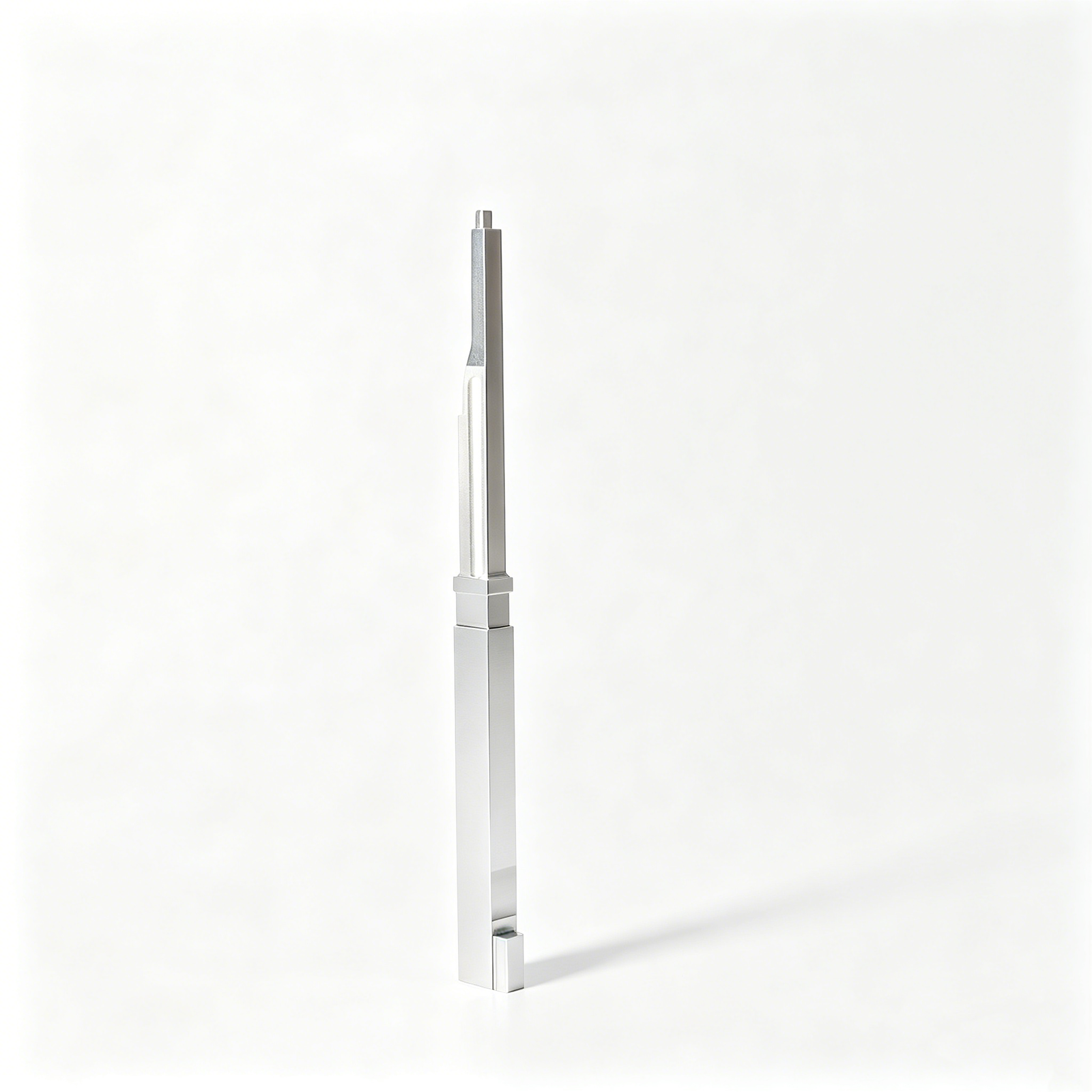



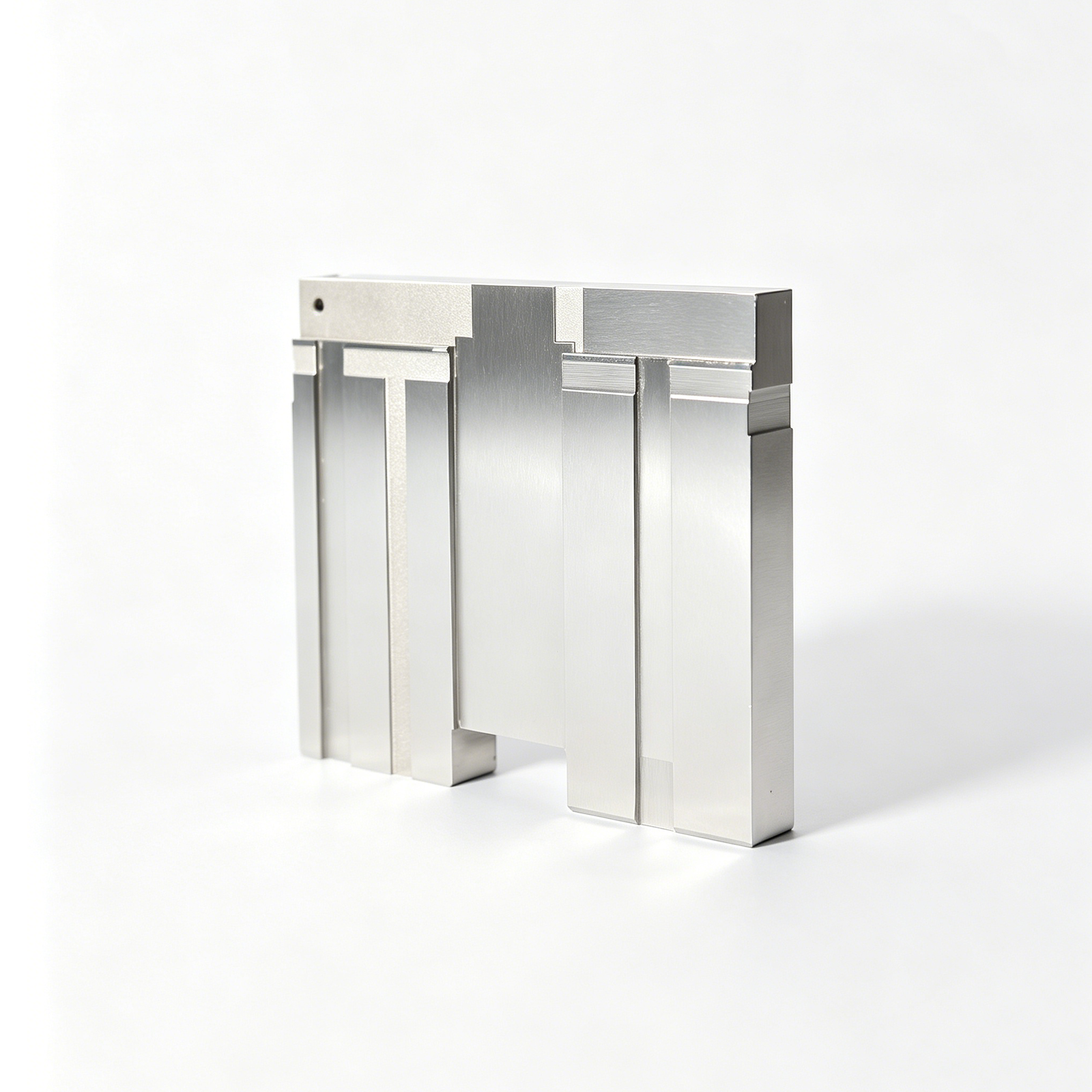
Related Components and Drawing-Based Quotations






Hot Runner Mold Components: Engineering Advantages
A drawing-led approach to process planning, critical dimensions, and inspection requirements before production commitments.
Drawing-Led DFM Review
Review drawings, models, datums, access constraints, and material requirements to identify manufacturability questions before quotation and production planning.
Process-Route Planning
Plan the appropriate sequence of CNC machining, EDM, grinding, heat treatment, fitting, and inspection around functional requirements.
Coordinated Precision Processes
Coordinate milling, turning, wire EDM, sinker EDM, and grinding so each operation supports the next machining stage.
Critical-Dimension Focus
Define critical-to-quality dimensions, datum relationships, surface requirements, and tolerance priorities that guide machining and measurement decisions.
Inspection Plan Alignment
Align inspection methods and reporting needs with the drawing, critical features, and order-specific quality expectations before final release.
Visible Revision Control
Keep drawing revisions, project questions, manufacturing changes, and delivery information visible throughout custom hot runner mold components work.
Hot Runner Components, Process Routes, and Support
Configurable component families and manufacturing processes for drawing-driven hot-runner molds, reviewed around critical dimensions, thermal interfaces, fit, and inspection requirements.

CNC Machining Services
Precision CNC machining and CNC machining services for drawing-defined hot-runner components, from plates and manifolds to inserts and support hardware. Process planning reviews datums, critical dimensions, material requirements, tool access, and inspection needs before production commitments are made.
Upload a Drawing
CNC Milling
Custom CNC milling services for prismatic mold plates, manifold features, pockets, channels, and mounting interfaces. The machining route is selected around feature access, clamping strategy, wall rigidity, finishing allowance, and the dimensions that affect assembly or flow-path alignment.
Upload a Drawing
CNC Turning
Precision CNC turning services for rotational parts such as nozzles, bushings, sleeves, pins, and threaded interfaces. Drawings should define functional diameters, concentricity, runout, thread requirements, surface condition, and any downstream grinding, EDM, or heat-treatment sequence.
Upload a Drawing
5-Axis Machining
5-axis CNC machining supports compound-angle, deep-access, and multi-face features where additional setups could increase positional risk. A drawing review assesses tool reach, collision clearance, datum transfer, stock condition, and whether five-axis motion provides a practical advantage for the specified geometry.
Upload a Drawing
Swiss & Micro Machining
Swiss machining and micro machining support small-diameter pins, sleeves, contact-related features, and miniature connector-tooling components. Evaluation focuses on part geometry, slenderness, material behavior, tolerances, surface requirements, and inspection methods appropriate to the functional dimensions.
Upload a Drawing
Wire & Sinker EDM
Wire EDM services and sinker EDM services address hardened materials, narrow slots, sharp internal geometry, fine profiles, and features inaccessible by conventional cutting. Electrode strategy, wire path, flushing, recast-layer considerations, and finish requirements should be agreed against the drawing and application.
Upload a Drawing
Precision Grinding
Precision surface and profile grinding brings controlled size, flatness, parallelism, profile, and finish to critical mold and die components. Grinding stock, heat-treatment distortion, datum condition, wheel access, and inspection method are reviewed before the finishing route is fixed.
Upload a Drawing
Mold Core Inserts & Mold Cavity Inserts
Precision mold core and cavity inserts are manufactured as configurable tooling components for defined molding functions. Review should cover steel selection, cooling or venting features, shutoff geometry, parting-line relationships, heat-treatment sequence, EDM needs, and the critical dimensions governing fit and molded-part quality.
Upload a Drawing
Ejector & Ejection Components
Ejector pins, sleeves, and ejection components are produced around movement, guidance, clearance, and wear considerations. Buyers should provide dimensions, material and hardness requirements, surface condition, mating-part context, lubrication or coating needs, and inspection priorities for functional fits.
Upload a Drawing
Core Pins, Guide & Locating Components
Core pins, guide pins, and locating components support repeatable alignment, positioning, and molded-feature formation. Manufacturing planning considers datum scheme, mating bores, fit class, length-to-diameter ratio, hardening and grinding sequence, and the dimensions most sensitive to assembly tolerance stack.
Upload a Drawing
Slides, Lifters, Gates & Mold Accessories
Mold slides, lifters, gates, and accessories are configured for motion, shutoff, feeding, and mold-function requirements. Drawings and assembly context help assess travel geometry, contact faces, wear surfaces, clearances, cooling interference, machining access, and the inspection plan for mating components.
Upload a Drawing
Connector Mold Components
Precision connector mold components support tooling used to form connector housings, terminals, cavities, and alignment features. The review addresses small features, pin density, positional relationships, tool steel, EDM or grinding requirements, wear points, and documentation needed for revision-controlled production.
Upload a Drawing
Stamping Die Components
Precision stamping die components are manufactured for cutting, forming, guiding, and locating operations. Process planning evaluates strip direction, working edges, clearance relationships, material and heat treatment, grinding allowance, mating interfaces, and measurement requirements for die assembly and maintenance.
Upload a Drawing
Injection Mold Components, MIM, CIM & Overmolding Tooling
Injection, MIM, CIM, and overmolding tooling components are considered within verified production scope when drawings and application requirements support the route. Review includes feed and vent interfaces, shrinkage-related geometry, insert relationships, thermal conditions, material selection, and inspection requirements.
Upload a Drawing
Machining Materials
CNC machining materials are selected from the drawing, application, machining behavior, strength, corrosion, wear, thermal, and finishing requirements. Material grade, condition, substitute approval, traceability expectations, and any heat-treatment sequence should be clarified before quotation and production.
Upload a Drawing
Surface Finishes & Heat Treatment
Surface finishing and heat treatment are planned as functional requirements, not default add-ons. Specify required hardness, coating or finish type, coverage, roughness, cosmetic limits, masking areas, distortion concerns, and which critical dimensions require final verification after treatment.
Upload a Drawing
Quality, Metrology & Documentation
Rapid prototyping and low-volume manufacturing support controlled iterations, tooling trials, spares, limited production quantities, and custom machined parts. A useful RFQ identifies revision level, quantity, target date, material, critical dimensions, finish, inspection reporting, and application context so the production route can be assessed responsibly.
Upload a Drawing
Prototyping & Low-Volume Production
Rapid prototyping and low-volume manufacturing support controlled iterations, tooling trials, spares, and limited production quantities. A useful RFQ identifies revision level, quantity, target date, material, critical dimensions, finish, inspection reporting, and application context so the production route can be assessed responsibly.
Upload a DrawingMaterials for Hot Runner Mold Components

Tool Steel Grades
Used for cores, cavity inserts, and structural hot-runner mold components where strength, machinability, and heat-treatment response must be balanced. Grade selection follows drawing requirements, contact conditions, machining access, and inspection priorities.

Pre-Hardened Steel
A practical choice for plates, inserts, and support components needing stable machining without a post-machining hardening cycle. Its supplied hardness can help manage distortion risk, but final suitability depends on load, wear, and dimensional requirements.

Hardened Tool Steel
Specified for components exposed to repeated sliding, abrasion, or demanding contact conditions. Heat-treatment sequence, grinding stock, EDM allowance, and critical-dimension inspection must be agreed before machining so finished geometry remains controlled.

Stainless Tool Steel
Considered when corrosion resistance matters alongside precision mold performance, such as applications involving humid storage or corrosion-sensitive resin environments. The selected grade, heat treatment, surface requirement, and mating conditions should be defined on the RFQ.

Copper Alloy Materials
Applied to selected thermal-management or electrode-related work where conductivity and machinability are central to the process route. Alloy choice is reviewed with feature geometry, EDM strategy, surface requirements, and the component’s operating environment.
Hot Runner Mold Components: Machining, EDM and Grinding

CNC Milling
CNC milling shapes plates, inserts, nozzle-seat features and supporting details from the approved drawing. Tool access, datum locations and remaining stock are reviewed so later EDM or grinding operations retain the intended geometry.


Wire EDM
Wire EDM produces precise profiles, slots and through-features without conventional cutting forces. SUUXIANG reviews start-hole access, wire path, corner requirements and datum transfer to determine whether the process suits the specified component.

Sinker EDM
Sinker EDM forms internal details, sharp-featured cavities and geometries that are difficult to machine conventionally. Electrode strategy, burn allowance, surface requirement and finishing sequence are considered alongside the drawing’s critical dimensions.


Fitting Inspection
Fitting and inspection verify functional interfaces, critical dimensions and specified relationships before release. Measurement planning follows the approved drawing, datums and revision status, with final documentation matched to the order’s verified inspection requirements.
Hot Runner Mold Components: Functional Accessories

Guide Elements
Guide pins, bushes, and alignment features can support repeatable plate movement and assembly positioning. Define fit, hardness, lubrication needs, datum relationship, and interchangeability requirements on the approved drawing before process planning.

Ejector Components
Ejector pins, sleeves, return elements, and related parts are planned around stroke, bearing surfaces, clearance, and contact conditions. Provide critical diameters, surface requirements, heat-treatment sequence, and any anti-rotation or venting details.

Locating Features
Locating rings, dowels, keys, and precision seating features establish controlled relationships between mold plates, inserts, and machine interfaces. Their dimensions should be tied to clear datums so machining, grinding, fitting, and inspection use one reference strategy.

Gate Inserts
Replaceable gate inserts and tip-adjacent support features can simplify service or accommodate defined gate geometry. SUUXIANG reviews material, access, EDM requirements, sealing interfaces, and surface condition with the hot runner assembly drawing.

Part Marking
Part numbers, revision marks, cavity identifiers, and orientation references help support assembly control and traceability. Specify marking content, location, method, legibility limits, and cosmetic restrictions so the requirement can be evaluated before production.
SUUXIANG Hot Runner Mold Components
SUUXIANG is the sole public-facing brand of Dongguan SuuXiang Precision Mold Co., Ltd., established in 2010 and based at 2nd Floor, Sanhe Industrial Park, Chang’an Town, Dongguan, Guangdong, China. Founder and legal representative XiaoCheng Huang leads the company. We support international engineering and sourcing teams with drawing-driven production of custom machined parts, precision mold components, connector tooling, and related die components.
For hot runner mold components, our workflow begins with the drawing, 3D model, material requirements and critical dimensions. DFM discussion addresses datum strategy, machining access, EDM requirements, grinding allowance, heat-treatment sequence and inspection expectations before quotation or production commitments are made.
What distinguishes SUUXIANG is disciplined coordination across CNC machining, EDM, grinding, fitting and inspection. We keep revision, quality and delivery requirements visible throughout the project, helping buyers evaluate process routes and exchange the evidence needed for controlled, drawing-based manufacturing.

Hot Runner Mold Components: From DFM to Inspection
Review Critical Dimensions First
SUUXIANG reviews drawings, models, datums, tolerance stacks, surface requirements, material, and heat-treatment sequence before production planning. This early discussion identifies dimensions that need a defined machining route, measurement method, or functional relationship with mating hot runner mold components.
- Identify critical-to-quality dimensions and functional datums
- Check tool access, wall conditions, and feature relationships
- Align drawing revisions before quotation and release
- Define required inspection evidence with the order

Plan CNC and EDM Routes
Each component requires a process route matched to its geometry, material condition, and tolerance priorities. SUUXIANG evaluates CNC machining access alongside wire EDM and sinker EDM needs, including electrode strategy, wire path, and finishing operations for precision hot runner tooling features.
- Match machining methods to geometry and access
- Review EDM requirements for internal or sharp features
- Consider heat-treatment timing in the process route
- Keep electrode and program changes under revision control

Protect Grinding and Fitting Allowances
Grinding and fitting should be planned as controlled finishing steps, not improvised corrections. SUUXIANG reviews stock allowances, reference surfaces, and assembly interfaces so final dimensions can be approached with an appropriate sequence for cores, inserts, locating elements, and related components.
- Assign grinding stock before final finishing
- Preserve reference surfaces through intermediate operations
- Review fit interfaces and movement-critical relationships
- Escalate drawing ambiguities before machining proceeds

Inspect to the Released Revision
Inspection planning connects the customer’s drawing requirements to the completed part and documentation. SUUXIANG confirms the applicable revision, critical dimensions, and reporting expectations, then coordinates measurement and delivery information around the verified inspection plan for the specific order.
- Verify drawing revision before final inspection
- Measure agreed critical dimensions and key features
- Match reports to the requested inspection scope
- Maintain visible communication on revisions and delivery

Why Engineering Teams Choose SUUXIANG for Hot Runner Mold Components
Compare a drawing-led workflow built around DFM, process planning, inspection evidence, and revision control.
← Swipe left or right to view →
Hot Runner Mold Components Production Workflow
A controlled project path that keeps requirements, critical dimensions, process decisions and inspection expectations visible from review through delivery coordination.
Review Drawings and Requirements
We review 2D drawings, 3D models, material, quantity, application and delivery needs, identifying critical dimensions, datums, surface requirements and inspection expectations before quotation.
Plan DFM and Process
The team confirms machining access, tolerance stack risks, heat-treatment sequence, EDM requirements, grinding allowance and fitting strategy, then aligns the route with revision-controlled requirements.
Machine Critical Component Features
CNC milling, turning, multi-axis machining, wire EDM or sinker EDM are applied as appropriate to produce configured hot runner mold components and related precision features.
Grind, Fit and Finish
Grinding and fitting operations address critical interfaces, locating surfaces and functional relationships, while the project team maintains visibility of approved revisions and outstanding technical questions.
Inspect, Pack and Coordinate
Final inspection follows the agreed plan; documentation, protective packing and delivery coordination are matched to the order requirements before components are prepared for shipment.
How to Source Hot Runner Mold Components
A controlled RFQ path for drawing-driven review, production alignment and inspection-ready delivery information.
Submit Your Drawing Package
Provide 2D drawings, available 3D models, material and heat-treatment requirements, quantity, critical dimensions, surface priorities, inspection needs and target delivery date.
Review DFM and Quotation
Align on datum strategy, machining access, EDM or grinding requirements, tolerance risks, inspection approach, revision status and the proposed manufacturing route before commitment.
Approve Production Details
Confirm the quotation, controlled drawings and agreed requirements; where needed, review sample or first-piece expectations before proceeding with the production plan.
Receive Delivery Updates
Track agreed production and delivery information while SUUXIANG coordinates machining, EDM, grinding, fitting and inspection against the approved order and verification plan.
Certificates and Quality Documentation
Customer Outcomes and Project Cases
Customer quotes and case summaries are published only after approval and verification of project context, scope, and measurable outcomes.
Hot Runner Mold Components FAQ
Practical RFQ, quality, delivery, and confidentiality questions for drawing-led component work.
What information should I send for a hot runner mold component quotation?
Can SUUXIANG quote low-volume hot runner mold components or prototype quantities?
How long do hot runner mold components take from sample to production?
Which materials can be considered for hot runner mold components?
Can you provide inspection reports with custom mold components?
How do you control revisions and protect drawing confidentiality?
Can hot runner mold components be shipped internationally?
What payment terms apply to a custom machining order?
The Complete Buyer’s Guide to Hot Runner Mold Components
Use a practical decision framework to specify hot runner mold components, compare supplier capabilities, control quality and cost risks, and avoid common sourcing mistakes before tooling release.
1. What Are hot runner mold components?
One hot runner assembly is the heated melt-delivery path between the injection machine nozzle and the mold’s cavity gates. Its manifold divides molten resin among nozzles; each nozzle and tip delivers melt through a defined gate location. Source: https://www.moldmasters.com/blog/what-is-a-hot-runner
Three thermal functions must work together: heaters add and maintain heat, thermocouples report zone temperature, and insulation limits heat transfer into surrounding mold plates. A temperature controller uses that feedback to regulate manifold and nozzle zones, while tip geometry influences the gate interface and flow behavior. Source: https://en.wikipedia.org/wiki/Hot_runner
Two runner concepts drive the sourcing decision. A cold runner solidifies with each shot and is ejected with the part, whereas a hot runner keeps the delivery path molten and can avoid a separate runner; the buyer’s core question is whether reduced runner material and process benefits justify the added tooling, controls, maintenance, and validation risk for the resin, part geometry, cavity count, and production plan.
2. Evolution of hot runner technology
1960s hot runner systems saw early, uneven adoption because maintaining a molten flow path inside a cooled mold was difficult. By the 1980s and 1990s, more reliable heaters, thermocouples, insulation, and zone controllers made the approach practical for broader production use. Source: https://en.wikipedia.org/wiki/Hot_runner
1-to-192+ nozzle layouts illustrate why thermal balance became a design discipline rather than a simple manifold-selection exercise. Modern hot runner mold components must hold defined process windows across cavities while accommodating resin-specific flow, residence-time, and temperature limits, especially for engineering resins. Source: https://www.moldmasters.com/blog/what-is-a-hot-runner
Valve-gate development added controlled mechanical shutoff at each gate, helping engineers manage filling sequence, gate vestige, and packing behavior. Buyers should therefore specify cavity count, resin grade, gate constraints, expected color-change frequency, and service-access needs early; reduced runner waste only delivers value when heaters, sensors, nozzles, seals, and wear items can be inspected and replaced without compromising datum relationships.
3. Types of hot runner mold components
Six common architectures differ mainly at the gate, not merely in nozzle count. Selection starts with resin behavior, cavity layout, cosmetic gate limits, cycle target, and the mold’s service-access plan.
| Type | Gate Appearance | Flow Control | Typical Fit | Selection Input |
|---|---|---|---|---|
| Open hot-tip | Small vestige | Thermal freeze-off | General direct gates | Cosmetic limit, resin |
| Sprue-gate | Larger sprue mark | Thermal freeze-off | Non-cosmetic structural parts | Gate location, trim allowance |
| Valve-gate | Minimal vestige | Pin-timed | Sequenced or cosmetic parts | Timing, actuator space |
| Single-nozzle | Depends on tip | One heated path | One gate or cavity | Shot size, stack space |
| Manifold multi-cavity | Depends on gate | Balanced heated branches | Multiple cavities | Layout, zone plan |
| Specialty approach | Application-specific | Resin-specific | Filled or sensitive resins | Resin data, residence limit |
Gate And Flow Choices
Open hot-tip gates leave a small vestige and suit many direct-gated parts; flow stops by freeze-off. Sprue-gate designs use a larger, more visible gate where direct gating is impractical.
Valve gates use a moving pin for timed opening and closing, supporting tighter sequencing and cleaner gate appearance. Pin, actuator, tip, and alignment access add maintenance work.
System Layouts
Single-nozzle systems feed one gate with the simplest heated path. They require the part gate location, resin, shot size, and available mold-stack envelope.
Manifold-fed multi-cavity systems split melt to several nozzles; layout must address fill balance, zone control, cavity count, and manifold service access.
Specialty Resin Strategies
Glass-filled, high-temperature, or shear-sensitive resins require resin grade, filler percentage, processing window, allowable residence time, and gate-pressure data. Confirm nozzle, tip, heater, and seal strategy during drawing review rather than selecting from a generic catalog.
4. Materials for hot runner mold components
Material choice must preserve melt-temperature stability while limiting heat loss into surrounding plates. Hot runner mold components should be selected from the resin, thermal layout, loads, and inspection-critical interfaces—not substituted by generic grade names.
| Component | Typical Material Direction | Primary Check |
|---|---|---|
| Manifold | Heat-resistant tool steel | Expansion and corrosion |
| Nozzle or tip | Tool steel or copper alloy | Heat transfer and wear |
| Valve pin | Wear-resistant steel | Glass-filled abrasion |
| Insulator | Thermally resistant material | Compression and cycling |
Heated Flow Components
Manifolds and nozzles commonly require heat-resistant tool steels where strength, corrosion resistance, and stable machining geometry are needed. Match thermal expansion across the manifold, nozzle, and supporting plates to protect seals and alignment.
Copper alloys can improve local heat transfer at selected heater interfaces, but require a load and wear review before use.
Tips And Valve Pins
Gate tips and valve pins see concentrated flow, cycling, and contact loads. Glass-filled resins accelerate abrasion, so wear-resistant steel, coatings, or surface treatment should be evaluated against gate geometry and serviceability.
Corrosive resins or additives require corrosion resistance without assuming that hardness alone solves the exposure.
Insulation And Validation

Insulating elements must reduce heat transfer while retaining fit through repeated thermal cycles. Resin processing temperature, dwell time, heater design, and thermocouple location determine the acceptable material window.
Final grades, treatments, and interfaces require application-specific drawing review, material documentation, and thermal analysis.
5. Custom hot runner mold components
SUUXIANG reviews custom hot runner mold components from the released part design outward. A drawing-based review connects gate intent, melt path, interfaces, thermal provisions, and inspection requirements before machining is quoted.
Define Functional Geometry
2D drawings should identify nozzle length, tip profile, gate diameter and location, manifold channel geometry, and mounting datums. 3D models expose plate clearances, tool access, cavity spacing, and interference risks.
1 cavity and multi-cavity layouts require the same gate and channel decisions to be checked against the intended pattern. Surface-treatment requirements belong on the drawing when they affect fits, wear surfaces, or measurement strategy.
Supply Process Inputs
1 resin data sheet should state grade, filler content, processing window, and any sensitivity to residence time. Molding parameters such as target melt temperature, injection rate, and expected cycle conditions help assess heater and sensor provisions.
2D tolerances should distinguish critical fits from general dimensions. A reference sample, mating-component drawing, or approved gate vestige standard can prevent interpretation changes after production begins.
- 2D drawing with datums and tolerances
- 3D model and cavity layout
- Resin grade and molding conditions
- Mating details or reference sample
Control Revisions And Evidence
1 revision-controlled package should identify the governing drawing, model revision, and open technical assumptions. Inspection points should trace back to critical dimensions, defined datums, and the agreed measurement method.
SUUXIANG can use this package to discuss CNC, EDM, grinding, fitting, and inspection routes within verified scope. A manufacturable quotation depends on resolving unclear interfaces before release.
6. Construction and quality requirements
Reliable hot runner mold components depend on controlled relationships between the manifold, nozzle, gate and surrounding plates. The drawing should define critical dimensions, datums, inspection evidence and acceptance limits before manufacture.
Sealing And Fit-Up
Manifold-to-nozzle concentricity affects gate alignment, sealing contact and wear. Specify functional datums, mating fits, surface condition and tightening sequence.
Sealing interfaces require controlled flatness, contact faces and clean melt-channel transitions. Define the assembly leakage-test medium, pressure, duration and acceptance criterion.
Thermal And Electrical Control
Heater and thermocouple locations determine whether each zone represents actual melt-path temperature. Require wiring identification, resistance checks, insulation-resistance checks and sensor continuity records.
Thermal balance depends on channel geometry, heater placement and insulation from cooled mold plates. Review zones against resin sensitivity, expected residence time and cavity-fill requirements.
Traceable Inspection
Dimensional inspection should measure drawing-defined CTQ features from stated datums. Reports should identify the revision, measurement method, actual results and disposition.
Material verification should match the ordered grade and heat-treatment requirement where specified. Assembly validation should confirm fit-up, electrical function, leakage prevention and protected wear surfaces before release.
7. Choosing a hot runner mold components supplier
Two supplier types serve this work: component machinists and complete-system providers. Evaluate the quoted scope against the drawing, interface responsibilities, and evidence required before release.
| Evaluation Area | Evidence To Request | Decision Risk |
|---|---|---|
| Drawing review | Marked-up DFM and assumptions | Unseen interface conflicts |
| Quality records | Traceability and inspection plan | Documentation mismatch |
| Lead time | Process-based schedule | Unrealistic commitments |
Drawing Review And DFM
A capable review identifies CTQ dimensions, datums, tool access, EDM or grinding allowances, and inspection method before pricing. Ask for written DFM feedback tied to the revision-controlled drawing.
- Which dimensions drive function?
- What assumptions remain open?
- Who approves drawing changes?
Capability And Evidence
Material traceability should connect the ordered grade, heat-treatment requirement, and part identification where the order requires it. Confirm that inspection reports, first-article evidence, and delivery documents match the agreed plan.
- CNC, EDM, grinding, and fitting route
- Measurement method for critical features
- Prototype and low-volume response plan
Scope, Support, And Communication
A component supplier machines specified parts; a complete hot-runner provider also owns manifold, nozzle, heater, controller, flow, and thermal-system selection. Ask who supports spares, interface changes, lead-time updates, and post-delivery revisions.
- Is system design included?
- Are electrical components supplied?
- What is the spare-part revision process?
8. Common hot runner mold components mistakes
Two linked decisions—resin behavior and gate strategy—must precede component specification. One pre-PO review should convert those decisions into checked interfaces, CTQs, and maintenance requirements.
Confirm Resin And Gate
Resin grade, filler content, color-change frequency, and gate vestige limit determine nozzle, tip, and gate choices. Review flow analysis or documented molding assumptions before releasing drawings.
Check Expansion And Interfaces
Thermal growth can change manifold, nozzle, plate, and gate relationships during operation. Verify assembly datums, clearance, preload, locating features, and mating dimensions against the complete mold stack.
Define CTQs And Temperature
Critical dimensions need datum references, tolerances, inspection methods, and acceptance criteria; copied nominal dimensions are insufficient. Map heater zones, thermocouple locations, controller interfaces, and allowable temperature variation before purchase order release.
Plan Service And Total Cost
Wear surfaces and service items require defined access for removal, cleaning, and replacement. Compare unit price with spares, inspection evidence, revision control, lead time, and downtime exposure before selecting a supplier.
9. Steps to launch a tooling project
A tooling launch should convert one RFQ into controlled, approved production inputs. For hot runner mold components, ownership of each decision must be explicit before machining starts.
Define The RFQ
1 complete package identifies resin grade, cavity count, gate concept, annual volume, mating interfaces, and critical-to-quality dimensions.
2 files—the released 2D drawing and 3D model—should carry revision identifiers; the buyer owns requirements, while the molder confirms process conditions.
Close The DFM Gate
3 parties—buyer, molder, and supplier—should review datums, tool access, steel condition, shrinkage assumptions, EDM strategy, and grinding stock.
1 signed specification freeze sets material, heat treatment, surface requirements, inspection method, and approved deviation process before production handoff.
Approve And Control Build
1 first-article or sample approval should confirm assembly fit, nozzle interfaces, wiring, thermocouple identification, and each temperature zone’s response.
100% of agreed critical dimensions should be recorded when specified; retain inspection records, define spare parts, and route every revision through written change approval.
10. hot runner mold components pricing
1 approved drawing package is the starting point for a defensible quotation. SUUXIANG prices the verified manufacturing scope, not an assumed catalog item or an unreviewed tolerance callout.
2 cost layers should be separated before suppliers are compared: part manufacture and project-specific validation. Material grade, heat-treatment sequence, EDM or grinding access, critical datums, reporting, and revision maturity can each change the process route.
3 quotation checkpoints reduce avoidable rework: confirm the 2D drawing, 3D model when available, quantity, mating context, target date, and inspection requirements. Lead time should be evaluated with capacity, purchased material, heat treatment, inspection, and approval dependencies visible.
| Pricing tier | Typical scope | Main cost drivers | Quotation evidence |
|---|---|---|---|
| Prototype | Single custom insert or pin | Setup, programming, material, EDM or grinding | Approved drawing and CTQ dimensions |
| Low-volume repeat | Small batch of controlled parts | Quantity, fixture reuse, heat treatment, inspection level | Revision status and reporting plan |
| Complex assembly | Matched components or multi-cavity work | Tolerance stack, fitting, electrodes, validation, schedule | Scope boundary, mating data, acceptance criteria |
Upload Your Hot Runner Mold Components Drawing
Include material, quantity, critical dimensions, inspection needs, and target delivery date for a focused technical quotation review.