
Injection Mold Slides and Lifters, Built From Your Drawing
SUUXIANG reviews injection mold slides and lifters for critical dimensions, DFM, machining access, EDM, grinding, and inspection planning.
Representative Components for Injection Mold Slide and Lifter Development





Related Component Families and Drawing-Based Quotations



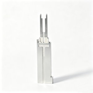


Injection Mold Slides and Lifters: Engineering Advantages
Drawing-led process planning for precision mold components with clear dimensional priorities, revision visibility, and inspection expectations.
Drawing-Led DFM Review
Review part geometry, datum strategy, machining access, shutoff areas, and ejection requirements before quotation or production commitments.
EDM Route Selection
Plan wire EDM, sinker EDM, electrode strategy, and finish requirements around features that CNC tools cannot access directly.
Grinding Stock Control
Define grinding allowance and heat-treatment sequence to protect critical fits, flatness, and surface requirements through final finishing.
Critical Dimensions First
Identify critical-to-quality dimensions, tolerance relationships, and measurement methods so process planning reflects functional component interfaces.
Visible Revision Control
Keep drawing revisions, clarified requirements, and delivery information aligned across project discussion, manufacturing, and final inspection.
Inspection Planned Early
Establish inspection expectations from the drawing, including datums, reporting needs, and traceable evidence appropriate to the order.
Precision Mold Components and Machining Services
Drawing-driven process routes for custom components, tooling work, and inspection requirements—reviewed against your material, critical dimensions, and production context.

CNC Machining Services
Precision CNC machining services for drawing-based parts requiring coordinated milling, turning, EDM, grinding, fitting, and inspection. Manufacturing routes are reviewed against material, critical dimensions, datum strategy, tool access, surface requirements, and order-specific quality expectations before commitment.
Upload a Drawing
CNC Milling
Custom CNC milling services for prismatic and contoured components, including mold inserts, plates, slides, and custom machined parts. Drawing review considers machining access, clamping, datum selection, cavity geometry, remaining stock, and downstream EDM or grinding requirements.
Upload a Drawing
CNC Turning
Precision CNC turning services for rotational features such as pins, sleeves, bushings, shafts, and locating elements. The process route should account for concentricity, runout, shoulders, threads, surface requirements, material condition, and any secondary milling, grinding, or inspection needs.
Upload a Drawing
5-Axis Machining
5-axis CNC machining supports multi-face geometry, angled features, complex profiles, and reduced re-clamping where the part design warrants it. Feasibility depends on tool reach, holding strategy, material condition, tolerance requirements, surface definition, and inspection access.
Upload a Drawing
Swiss & Micro Machining
Swiss machining and micro machining support small, slender, and detail-intensive components where stability and feature control matter. Review includes diameter-to-length relationships, critical features, material behavior, burr control, measurement method, quantity, and handling requirements.
Upload a Drawing
Wire & Sinker EDM
Wire EDM and sinker EDM services address hardened materials, internal profiles, sharp-corner requirements, fine details, and features with limited conventional tool access. Electrode strategy, wire path, flushing, EDM allowance, recast-layer considerations, and finishing requirements are reviewed by application.
Upload a Drawing
Precision Grinding
Precision surface and profile grinding is used when flatness, parallelism, profile control, finish, or tightly controlled stock removal is required. Grinding planning considers heat-treatment sequence, grinding allowance, datum transfer, part rigidity, surface specification, and inspection method.
Upload a Drawing
Mold Core & Cavity Inserts
Precision mold core and cavity inserts are configured from approved drawings and molding requirements. Material, heat treatment, cavity details, shutoff conditions, cooling interfaces, polish requirements, datum strategy, and mating relationships should be defined before process planning.
Upload a Drawing
Ejector & Ejection Components
Ejector pins, sleeves, and ejection components are produced to drawing-defined dimensions and functional interfaces. Review should address fit, clearance, hardness condition, surface requirement, guidance, travel, wear points, mating components, and inspection priorities for the intended mold assembly.
Upload a Drawing
Core Pins, Guide & Locating Components
Core pins, guide pins, and locating components require controlled relationships to their mating parts. Manufacturing review focuses on diameter, concentricity, fit class, datum references, wear surfaces, heat-treatment sequence, retention features, and the measurement approach used for acceptance.
Upload a Drawing
Slides, Lifters, Gates & Mold Accessories
Mold slides, lifters, gates, and accessories are configurable component families for motion, release, feeding, and supporting mold functions. Process planning considers travel geometry, shutoff surfaces, wear interfaces, tool access, fitting allowance, material treatment, and assembly relationships.
Upload a Drawing
Connector Mold Components
Precision connector mold components support tooling for connector features where small pitches, repeated geometry, alignment, and mating conditions are important. Drawing review identifies critical dimensions, material and hardness requirements, EDM needs, polishing, inspection points, and revision-controlled interfaces.
Upload a Drawing
Stamping Die Components
Precision stamping die components are manufactured for drawing-defined cutting, forming, guiding, and support functions. Process selection considers material condition, hardness, clearance relationships, edge requirements, wire-EDM strategy, grinding stock, fitting needs, and inspection criteria.
Upload a Drawing
Injection, MIM, CIM & Overmolding Tooling
Injection, MIM, CIM, and overmolding tooling work is assessed within verified production scope. A responsible review considers molding material, shrinkage assumptions, part geometry, inserts, gating, venting, tool steel requirements, surface needs, molding interfaces, and required component documentation.
Upload a Drawing
Machining Materials
CNC machining materials are selected against the drawing, application, heat-treatment condition, corrosion needs, wear behavior, machinability, and inspection requirements. Material availability and equivalency should be confirmed for each RFQ rather than assumed from a general material list.
Upload a Drawing
Surface Finishes & Heat Treatment
Surface finishing and heat treatment are specified according to function, material, dimensional risk, and mating conditions. Review should establish the required finish, treatment sequence, masking or protection needs, post-treatment stock, hardness verification, and any final grinding or inspection steps.
Upload a Drawing
Quality, Metrology & Documentation
Precision inspection, metrology, and quality documentation are planned around drawing-defined critical dimensions and order requirements. The inspection plan should identify datums, measurement methods, sampling or reporting needs, revision status, material evidence, and the records required for final delivery.
Upload a Drawing
Prototyping & Low-Volume Production
Rapid prototyping and low-volume manufacturing support drawing-driven evaluation, fixture development, tooling trials, and controlled production quantities. RFQs should state quantity, material, delivery target, critical dimensions, surface requirements, inspection needs, and any application context affecting manufacturability.
Upload a DrawingMaterials for Injection Mold Slides and Lifters

Pre-Hardened Tool Steel
A practical starting material for slide bodies and supporting components where stable machining and moderate wear resistance are required. Final selection depends on drawing requirements, working load, heat-treatment condition, and mating wear surfaces.

Through-Hardening Tool Steel
Considered for forming details, lifter heads, and wear-prone inserts requiring a hardened working surface. Machining allowance, heat-treatment distortion risk, finish grinding, and critical-dimension inspection should be planned before production.

Cold-Work Tool Steel
Often evaluated for components exposed to repeated sliding contact, localized loading, or demanding wear conditions. The appropriate grade, hardness range, EDM strategy, and post-machining finishing route require confirmation from the project specification.

Stainless Tool Steel
Suitable for applications where corrosion resistance or clean processing conditions influence material choice. Material grade, heat treatment, surface finish, and dimensional stability are reviewed with the application, molding environment, and customer drawing.

Copper Alloy Inserts
May be considered for localized thermal-management inserts where heat transfer affects the molding process. Insert geometry, joining method, machining access, wear exposure, and compatibility with adjacent tool steel must be reviewed case by case.
Manufacturing Processes for Injection Mold Slides and Lifters


Wire EDM Cutting
Wire EDM produces narrow slots, sharp internal profiles, and hardened contour features where milling access is limited. The wire path, start-hole location, and required corner condition are planned from the component geometry.

Sinker EDM Forming
Sinker EDM forms detailed cavities, shutoff areas, and difficult internal geometry using a planned electrode strategy. Electrode wear, finish requirements, and subsequent fitting or polishing allowances should be defined early.


Component Fitting Assembly
Fitting verifies the working relationship among slides, lifters, guides, and mating inserts. The review focuses on travel, clearance, contact surfaces, and potential interference so assembly requirements remain visible through production.

Final Dimensional Inspection
Inspection confirms the agreed critical dimensions, datums, and reporting requirements for injection mold slides and lifters. Measurement methods and documentation are aligned to the order, drawing revision, and verified inspection plan.
Injection Mold Slides and Lifters: Accessory Features to Review

Guide Components
Guide pins, bushings, wear plates, and gibs can be reviewed for slide travel, alignment, lubrication provisions, and replaceable wear interfaces within the mold assembly.

Locating Interfaces
Dowel holes, keys, stops, and locating blocks help establish repeatable assembly positions. Their datum relationship, fit requirements, and inspection method should be defined on the drawing.

Cam Pin Interfaces
Angle-pin, wedge, and lock-block interfaces can be considered where a slide requires controlled actuation and support. Review must account for travel, contact geometry, clearance, and maintenance access.

Fastening Features
Threaded holes, counterbores, socket-head fasteners, and retainer arrangements can be machined to drawing requirements. Specify thread standards, tightening access, mating parts, and any anti-rotation requirement.

Ejection Interfaces
Lifter seats, ejector-pin bores, retainer features, and ejector-plate interfaces can be planned around motion, alignment, and grinding allowance. Critical clearances and assembly sequence require drawing review.
About SUUXIANG Precision Manufacturing
SUUXIANG is the sole public-facing brand of Dongguan SuuXiang Precision Mold Co., Ltd., established in 2010 in Chang’an Town, Dongguan, Guangdong, China. XiaoCheng Huang is the founder and legal representative. We support international engineering, sourcing, and quality teams that need drawings and specifications translated into inspected precision-manufactured parts.
Our scope combines CNC milling and turning, multi-axis machining, EDM, precision grinding, fitting, and inspection for custom CNC parts, mold components, connector tooling, and die components. For injection mold slides and lifters, each project begins with the drawing, application context, material requirements, and critical dimensions.
What distinguishes our approach is disciplined review before commitments are made. We examine datum strategy, machining access, EDM or grinding requirements, heat-treatment sequence, inspection expectations, and revision status so the proposed process route reflects the actual component requirement.

Injection Mold Slides and Lifters: DFM Through Inspection
Drawing-Led DFM Review
SUUXIANG reviews injection mold slides and lifters against the drawing, 3D model, application and mating conditions before commitments are made. The discussion focuses on critical dimensions, datum relationships, undercut release, tool access and risks that can affect machining, fitting or inspection.
- Confirm critical-to-quality features and datum strategy
- Review slide travel, lifter clearance and shutoff geometry
- Identify tolerance-stack and mating-component risks
- Clarify revision status before process planning

Machining and EDM Access
Complex side-action components often require more than a single machining route. SUUXIANG plans CNC milling, multi-axis access, wire EDM or sinker EDM around feature geometry, corner conditions and electrode requirements, while keeping machining sequence and accessible reference surfaces visible in the review.
- Assess cutter reach and fixture approach
- Define wire paths for narrow or enclosed details
- Review electrode strategy for inaccessible cavities
- Preserve usable datums through machining stages

Grinding Allowance and Fitting
Grinding and fitting decisions should be established before stock removal is finalized. SUUXIANG reviews allowance, heat-treatment sequence, sliding interfaces and adjustment requirements so precision surfaces can be finished with an appropriate process route rather than relying on unplanned rework.
- Set grinding stock for critical finished faces
- Coordinate heat treatment with finish operations
- Review wear surfaces and sliding contact areas
- Plan fitting points and adjustment access

Order-Specific Inspection Planning
Inspection planning is tied to the order, drawing revision and identified critical features. For injection mold slides and lifters, SUUXIANG aligns measurement methods, reporting expectations and traceability needs before production, then supplies documentation that matches the verified inspection plan and customer requirements.
- Define dimensions requiring recorded results
- Match measurement methods to feature geometry
- Confirm report format and quantity requirements
- Maintain drawing-revision and delivery traceability

Why Source Injection Mold Slides and Lifters Through SUUXIANG
For injection mold slides and lifters, compare the drawing review, revision visibility, and inspection alignment behind the quotation.
← Swipe left or right to view →
Injection Mold Slides and Lifters: From Drawing Review to Delivery
A controlled workflow for custom mold components, centered on manufacturability, critical dimensions, revision visibility, and inspection requirements.
Review Drawings and Requirements
We review 2D drawings, 3D models, material, quantity, application context, delivery targets, and critical-to-quality dimensions before confirming a feasible quotation path.
Plan Process and Datums
The team defines datum strategy, machining access, tolerance priorities, heat-treatment sequence, EDM requirements, grinding allowance, and inspection methods for each component.
Machine Critical Component Features
CNC milling, turning, multi-axis machining, or micro-machining are selected according to geometry, stock condition, tool access, and the approved process route.
Apply EDM and Grinding
Wire EDM, sinker EDM, and precision grinding address detailed profiles, difficult access, hardened conditions, and finish-critical surfaces specified by the drawing.
Fit and Verify Components
Where required, components are fitted and inspected against the agreed drawing revision, critical dimensions, datum references, surface requirements, and project-specific reporting plan.
Pack and Coordinate Delivery
Final documentation follows the verified inspection plan, while packing, revision records, and delivery coordination are aligned with the confirmed order requirements.
Start Your Injection Mold Slides and Lifters RFQ
Send the technical inputs needed for a disciplined drawing review, process planning and inspection discussion.
Share Drawings and Models
Provide the latest 2D drawing and, where available, 3D model with revision status, assembly context and any interfaces affecting slide or lifter function.
Define Material and Quantity
State the required material, heat treatment, quantity and application conditions so the proposed machining, EDM, grinding and fitting route can be assessed.
Identify Critical Requirements
Mark critical dimensions, datums, surface requirements, shutoff areas and functional relationships, then specify the inspection method or reporting expectations for acceptance.
Confirm Delivery Priorities
Share the target delivery date, prototype or production intent, packaging needs and revision constraints so scope, quality planning and delivery coordination remain visible.
Injection Mold Slides and Lifters: Certificates and Quality Documentation
Project Evidence for Injection Mold Slides and Lifters
Approved customer testimonial pending permissioned project evidence and verified outcome documentation.
Approved customer testimonial pending permissioned project evidence and verified outcome documentation.
Approved customer testimonial pending permissioned project evidence and verified outcome documentation.
Injection Mold Slides and Lifters FAQ
Practical answers for drawing-based sourcing, inspection planning, and controlled project coordination.
What drawings do you need for injection mold slides and lifters?
Can you manufacture injection mold slides and lifters from a custom drawing?
What is the MOQ for injection mold slides and lifters?
Can you provide samples before a full production order?
How long does it take to produce custom slide or lifter components?
What materials and heat treatments can be specified?
What inspection reports are available for injection mold slides and lifters?
How are shipping and IP protection handled for custom mold-component projects?
The Complete Buyer’s Guide to injection mold slides and lifters
Use a practical decision framework to select injection mold slides and lifters, evaluate supplier engineering and quality controls, compare automation options, and avoid DFM, maintenance, cost, and launch mistakes before tooling approval.
1. What Are injection mold slides and lifters?
Two mold halves separate along a defined line of draw; any feature that mechanically traps the part during straight opening is an undercut. Injection mold slides and lifters are moving mold elements that form and then clear those features before normal ejection. https://www.fictiv.com/articles/injection-molding-sliders-and-lifters-vs-handloads
One slide usually forms an external side feature—such as a side hole, slot, or external overhang—and travels laterally away from the part during mold opening. Its locking, guiding, cooling, and wear interfaces add alignment and maintenance requirements, so a slide is a mold-system decision rather than merely an added insert. https://www.fictiv.com/articles/injection-molding-sliders-and-lifters-vs-handloads
One lifter normally releases an internal undercut by combining ejector-driven vertical travel with angled lateral withdrawal. That motion can protect the molded feature during release, but its clearance, shutoff, ejection timing, and inspection requirements affect cycle reliability, cosmetic quality, tool complexity, and initial tooling investment. https://www.upmold.com/injection-mold-slide-and-lifter-design
2. How Side-Action Tooling Evolved
Two-part molds cannot release every undercut in the line of draw, so low-volume programs can use hand-loaded inserts that an operator places and removes each cycle. That route avoids automatic mechanism investment but adds handling and cycle-to-cycle control requirements. Source: https://www.fictiv.com/articles/injection-molding-sliders-and-lifters-vs-handloads
Cam-pin slides formalized repeatable lateral motion: an angled pin withdraws from the slide body during mold opening, while an angle block locks the slide against molding pressure. As production volume, dimensional repeatability, and connector side-feature complexity increase, buyers should specify datum locations, shutoff geometry, wear surfaces, cooling access, and serviceable components in the drawing-review package. Source: https://www.fictiv.com/articles/injection-molding-sliders-and-lifters-vs-handloads
Sensor-monitored hydraulic mechanisms add sequence confirmation where automated cells, long slides, or ejection interlocks make an unverified position a production risk. One published mold-design standard calls for proximity switches to register ejector movement when ejection occurs under slide detail; treat such details as application-specific engineering requirements, not universal rules. Source: https://upmold.com/injection-mold-slide-and-lifter-design
3. Types of injection mold slides and lifters
Two motion paths govern selection: slides retract from external undercuts, while lifters rise and shift from internal features. Choose against geometry, molding force, cycle volume, and maintenance access.
| Mechanism | Motion | Undercut | Volume Fit | Advantage | Decision Trigger |
|---|---|---|---|---|---|
| Angle-pin slide | Lateral | External | Medium-high | Automatic | Standard side feature |
| Powered slide | Controlled lateral | External | Medium-high | Force or sequence | Cam is inadequate |
| Wedge lock | Locks slide | External | Any | Resists molding load | Large forming face |
| Blade or rod lifter | Upward plus lateral | Internal | Medium-high | Automatic ejection | Internal hook or recess |
| Hand-loaded insert | Manual placement | Internal or external | Prototype-low | Low tooling investment | Automation is uneconomic |
Cam Slides And Locks
Angle-pin slides convert mold opening into lateral travel for outside holes, slots, and side hooks.
Wedges lock the forming face against injection load; specify them when side-action repeatability is critical.
Powered Slides
Hydraulic or pneumatic cylinders drive programmed side travel where a cam lacks stroke, timing, or force.
Specify sensors, sequence requirements, and service access; added controls suit recurring production, not simple geometry.
Lifters And Handloads
Blade or rod lifters move upward and sideways with ejection to clear internal undercuts.
Hand-loaded inserts form difficult features without automation, but labor and handling variation favor prototype or low-volume work.
Combined Actions
Slide-plus-lifter tools address parts having external and internal undercuts in one molding cycle.
Review clearance, ejection retention, and action sequence together; interference is a mold-layout issue, not a late fitting fix.
4. Materials and Surface Treatments
Material selection begins with the resin, contact load, cosmetic requirement, and planned maintenance interval. For injection mold slides and lifters, select the assembly as mating surfaces—not isolated part grades.
| Component | Primary Choice Driver | Service Consideration |
|---|---|---|
| Tool-steel body | Load and forming detail | Toughness versus repairability |
| Hardened wear element | Sliding wear | Galling and lubrication |
| Bronze plate | Replaceable bearing | Wear debris and clearance |
| Special insert | Corrosion, polish, cooling | Application-specific validation |
Tool Steel And Hardness
Hardened tool-steel bodies suit loaded forming and locking areas when wear life matters. Hardness must be balanced against toughness, grindability, and repair welding risk; specify the heat-treatment condition on the drawing.
Wear And Friction Pairs
Bronze wear plates can provide a sacrificial, replaceable bearing surface against steel. Match clearance, lubrication access, and anti-galling treatment to travel frequency and filled-resin contamination; capture replacement criteria in maintenance records.
Inserts And Surface Needs
Corrosion-prone resins or environments may justify corrosion-resistant inserts, while cosmetic faces require a polishable material and compatible finish route. Abrasive glass- or mineral-filled polymers increase wear, making replaceable inserts more practical than rebuilding a complete slide.
5. Custom Features for injection mold slides and lifters
Custom features should solve a defined molding, ejection, cooling, or traceability problem. For injection mold slides and lifters, each added detail should have a documented function and validation method.
Forming Details And Inserts
A replaceable forming insert localizes wear, damage risk, or geometry changes without remaking the complete slide or lifter. Specify datum references, shutoff surfaces, texture boundaries, and interchangeability requirements on the drawing.
- Cavity-specific ID marks
- Textured forming faces
- Replaceable core details
Process-Support Features
Vents, cooling circuits, sensors, travel stops, and return mechanisms require clear access and maintenance provisions. State the resin, annual volume, cycle target, and acceptable witness marks so the feature addresses an actual production risk.
- Vent location and cleaning access
- Cooling connection requirements
- Sensor signal and travel position
Control Customization Scope
A validation plan should define the critical dimensions, cosmetic acceptance criteria, sampling method, and functional trial conditions. Avoid adding mechanisms solely for theoretical flexibility when a fixed insert, simpler stop, or manual changeover meets the requirement.
- 2D drawing and 3D model
- Tolerance and datum priorities
- Resin and appearance standard
- Validation and inspection evidence
6. Injection mold slides and lifters: quality essentials
Three review questions determine whether injection mold slides and lifters run predictably: what carries injection load, what controls motion, and what releases the part. Approve answers on the drawing and tool-design package before steel is cut.
Shutoffs And Locking
3° shutoff draft in the direction of slide travel is a common starting convention; less draft raises galling, flash, and fitting sensitivity. Confirm that a positive wedge or lock backs the full pressure-facing forming area, rather than relying on the cam pin alone.
Source: https://upmold.com/injection-mold-slide-and-lifter-design
Guidance And Clearances
0.20 in rear clearance is one published slide-detail guideline; the required value must still account for part deflection, travel, and manufacturing tolerances. Review guide and wear surfaces for accessible lubrication and adjustment, then check every open and closed position for interference.
Source: https://upmold.com/injection-mold-slide-and-lifter-design
- Are wear plates replaceable without rebuilding the slide?
- Does the travel stop prevent pin, cavity, or ejector collision?
- Can alignment be verified from defined datums?
Ejection, Cooling, And Retention
11° is a published lifter-angle limit before special design considerations; validate the actual angle against undercut release and ejection stroke. Check whether the part can drag on the lifter, remain retained on its detail, or contact ejectors during return.
Deep ribs and broad slide details need an explicit venting and cooling review; trapped gas, localized heat, and poor lubrication access accelerate wear and create cosmetic defects. Source: https://upmold.com/injection-mold-slide-and-lifter-design
7. How to Evaluate a Tooling Supplier
A 2D drawing, 3D model, and CTQ list should drive supplier selection. For injection mold slides and lifters, assess documented engineering response, not quotation speed alone.
| Decision Area | Request Before PO | Warning Sign |
|---|---|---|
| DFM | Marked-up drawing and risk log | Generic acceptance |
| Capability | Process and inspection plan | Unspecified measurement |
| Schedule | Milestone-based lead time | Unqualified promise |
| Support | Change and spare-parts plan | Verbal-only control |
Review The DFM Response
Within 2 business days, request a marked-up DFM identifying datum conflicts, tool access, EDM or grinding needs, and risk items.
For side actions, request mold-flow review or a documented reason it is unnecessary.
Verify Production Evidence
Material certificates must link heat, grade, and heat-treatment requirements to the ordered parts.
Inspection plans should name CTQs, datums, instruments, sampling, and report format before PO release.
Test Project Control
Revision-controlled drawings should govern machining, fitting, trial support, and any deviation approval.
Spare-part recommendations should identify wear components, interchangeability, and the evidence needed for repeat orders.
8. Common Buyer Mistakes and Prevention
Early DFM prevents many side-action failures before steel is cut. For injection mold slides and lifters, convert each assumption into a documented question at DFM, quotation, and trial.
Choose The Release Method
One undercut does not automatically require a slide; a lifter, hand load, part redesign, or secondary operation may fit the volume and geometry better. The wrong choice adds tool complexity, cycle risk, or recurring labor.
At DFM, ask: Which release method clears the feature, and what volume justifies automatic action? At quotation, confirm included mechanisms and any manual handling.
Define Motion And Material
Three items need explicit review: shutoff draft, retracted clearance, and resin shrinkage or drag behavior. Missing them can cause scuffing, flash, sticking, or interference during ejection.
At DFM, ask: What draft, travel clearance, resin grade, and ejection sequence are verified on the approved model? At trial, inspect witness marks and whether the part remains on the intended mold half.
Control Scope And Changes
Every critical tolerance needs a datum, measurement method, and acceptance limit; a vague tolerance cannot drive machining or inspection. Unplanned wear surfaces, spares, and change requests can later become downtime, rework, or disputed cost.
At quotation, ask: Which drawing revision, materials, heat treatment, inspection report, maintenance items, and trial support are included? Before any change, require written DFM review and compare like-for-like quote scope.
9. From RFQ to Production Launch
Production release should follow documented decision gates, not a quotation-to-build shortcut. For injection mold slides and lifters, each gate should assign an owner, acceptance evidence, revision status, and an escalation path.
RFQ And DFM Gate
Gate 1 starts with the controlled 2D drawing, 3D model, resin, quantity, molding context, CTQ dimensions, and reporting requirements.
Engineering records datum strategy, shutoff and travel risks, tool access, electrode or wire path, grinding stock, and open DFM actions.
Scope And Design Approval
Gate 2 aligns quoted scope with the approved design: component boundaries, material and heat treatment, fitting responsibilities, inspection method, delivery milestones, and revision control.
Procurement confirms commercial terms while program management records design approval and any deviations before machining begins.
Trial Through Production Release
Gate 3 reviews first-article or trial evidence against the drawing, including critical dimensions, functional movement, surface condition, and corrective-action status.
Quality closes nonconformities, validates the agreed process evidence, and defines maintenance ownership, spare-part responsibility, change control, and release authorization.
10. Injection Mold Slide and Lifter Costs
10 cost drivers should be itemized before comparing injection mold slides and lifters. Geometry, motion, materials, thermal control, controls, precision, validation, and spare strategy can change the process route without changing the part drawing.
1 quotation is comparable only when both suppliers define the same tooling scope: mechanism design, mold-base interfaces, steel condition, heat treatment, electrodes, fitting, inspection, tryout, and documentation. A lower initial figure may exclude lifecycle assumptions such as planned maintenance, replacement wear items, or onsite/service support.
2 RFQs should state expected production volume and service responsibility alongside the drawing package. SUUXIANG can review those inputs against the requested manufacturing scope and provide an evidence-based quotation rather than an unsupported price range.
| Cost driver | Relative impact | What to normalize |
|---|---|---|
| Slide size and travel | High | Body mass, guides, cam load, stroke |
| Lifter geometry | High | Angle, forming detail, ejection clearance |
| Mechanism count | High | Repeated components, fitting, timing |
| Locking and actuation | High | Cam, hydraulic, or mechanical scope |
| Steel and treatment | Medium–high | Grade, hardness, coating, wear surfaces |
| Cooling | Medium–high | Channels, plugs, leak test, access |
| Sensors | Medium | Type, mounting, wiring, validation |
| Tolerances | High | Grinding, EDM, datum inspection |
| Validation | Medium–high | Tryout criteria, reports, revisions |
| Maintenance spares | Medium | Wear plates, locks, pins, spare policy |
Upload Injection Mold Slides and Lifters Drawings for Review
Include material, quantity, critical dimensions, inspection requirements, and delivery target so our team can assess DFM, process route, and project documentation.