
Leader Pins and Bushings for Drawing-Based Tooling
Send your drawing for DFM review, process planning, and inspected leader pins and bushings matched to critical dimensions and documentation needs.
Representative Components for Leader Pins and Bushings Projects





Related Configurable Component Families


Why Engineering Teams Choose SUUXIANG for Leader Pins and Bushings
Drawing-driven planning keeps fit, process choices, inspection priorities and revisions visible before production begins.
Drawing-Led DFM Review
We review drawings, models, datums, critical dimensions and mating context to identify manufacturability questions before quotation and production planning.
Coordinated Process Planning
CNC machining, EDM, grinding and fitting are planned around geometry, tool access, machining allowance and required component interfaces.
Critical Dimensions First
Project discussions define dimensional priorities, surface requirements and inspection methods so production attention follows the features that affect mold function.
Revision-Controlled Communication
Drawing updates, open technical questions and delivery information remain visible throughout the project to reduce ambiguity between engineering and sourcing teams.
Inspection Matched to Requirements
Inspection planning is aligned with the order, critical features and reporting needs, supporting traceable acceptance of finished leader pins and bushings.
Precision Components by Function
Explore configurable manufacturing and mold-component families planned around drawings, critical dimensions, process access, inspection requirements, and revision control.

CNC Machining Services
Precision CNC machining services for drawing-based custom machined parts requiring coordinated milling, turning, EDM, grinding, fitting, and inspection. We review material, datums, critical dimensions, quantity, and quality requirements before confirming a practical manufacturing route.
Upload a Drawing
CNC Milling
Custom CNC milling services for prismatic parts, pockets, contours, holes, and molded-feature details. Tool access, workholding, datum selection, remaining stock, and surface requirements are reviewed to support stable machining and inspection.
Upload a Drawing
CNC Turning
Precision CNC turning services for shafts, pins, bushings, sleeves, threaded features, and concentric diameters. Drawings should identify functional datums, runout requirements, material condition, surface finish, and any downstream grinding or heat-treatment sequence.
Upload a Drawing
5-Axis Machining
5-axis CNC machining for complex surfaces, angled features, compound contours, and parts where fewer setups can protect positional relationships. Feasibility depends on tool reach, clamping strategy, material, tolerance requirements, and inspection access.
Upload a Drawing
Swiss & Micro Machining
Swiss machining and micro machining for small-diameter pins, shafts, sleeves, and connector-related features. A drawing review addresses feature proportions, material behavior, concentricity, cutoff considerations, critical dimensions, and realistic inspection methods.
Upload a Drawing
Wire & Sinker EDM
Wire EDM and sinker EDM services for sharp internal profiles, hardened material, narrow slots, complex cavities, and features beyond conventional tool access. Electrode strategy, wire path, corner conditions, recast-layer considerations, and finish requirements should be defined early.
Upload a Drawing
Precision Grinding
Precision surface and profile grinding for controlled flatness, parallelism, thickness, profiles, and final-size features. Grinding stock, heat-treatment condition, datum strategy, surface requirements, and measurement methods are planned against the drawing.
Upload a Drawing
Mold Core & Cavity Inserts
Precision mold core inserts and mold cavity inserts manufactured from customer drawings for mold-function requirements. The review considers steel selection, cavity geometry, machining and EDM access, heat-treatment sequence, polishing expectations, shutoff areas, and critical inspection dimensions.
Upload a Drawing
Ejector & Ejection Components
Ejector pins, sleeves, and ejection components produced for specified motion, fit, wear, and alignment conditions. Provide mating-part context, material and hardness requirements, diameter tolerances, surface finish, and any lubrication or venting-related features.
Upload a Drawing
Core Pins, Guide & Locating Components
Core pins, guide pins, and locating components for controlling mold alignment, feature formation, and repeatable positioning. Functional fits, datum relationships, material condition, wear surfaces, mating components, and inspection priorities should accompany the drawing.
Upload a Drawing
Slides, Lifters, Gates & Mold Accessories
Mold slides, lifters, gates, and accessories configured for the specified mold action and geometry. Manufacturing planning considers travel interfaces, angled features, bearing surfaces, shutoffs, cooling or gating details, material treatment, and fitting requirements.
Upload a Drawing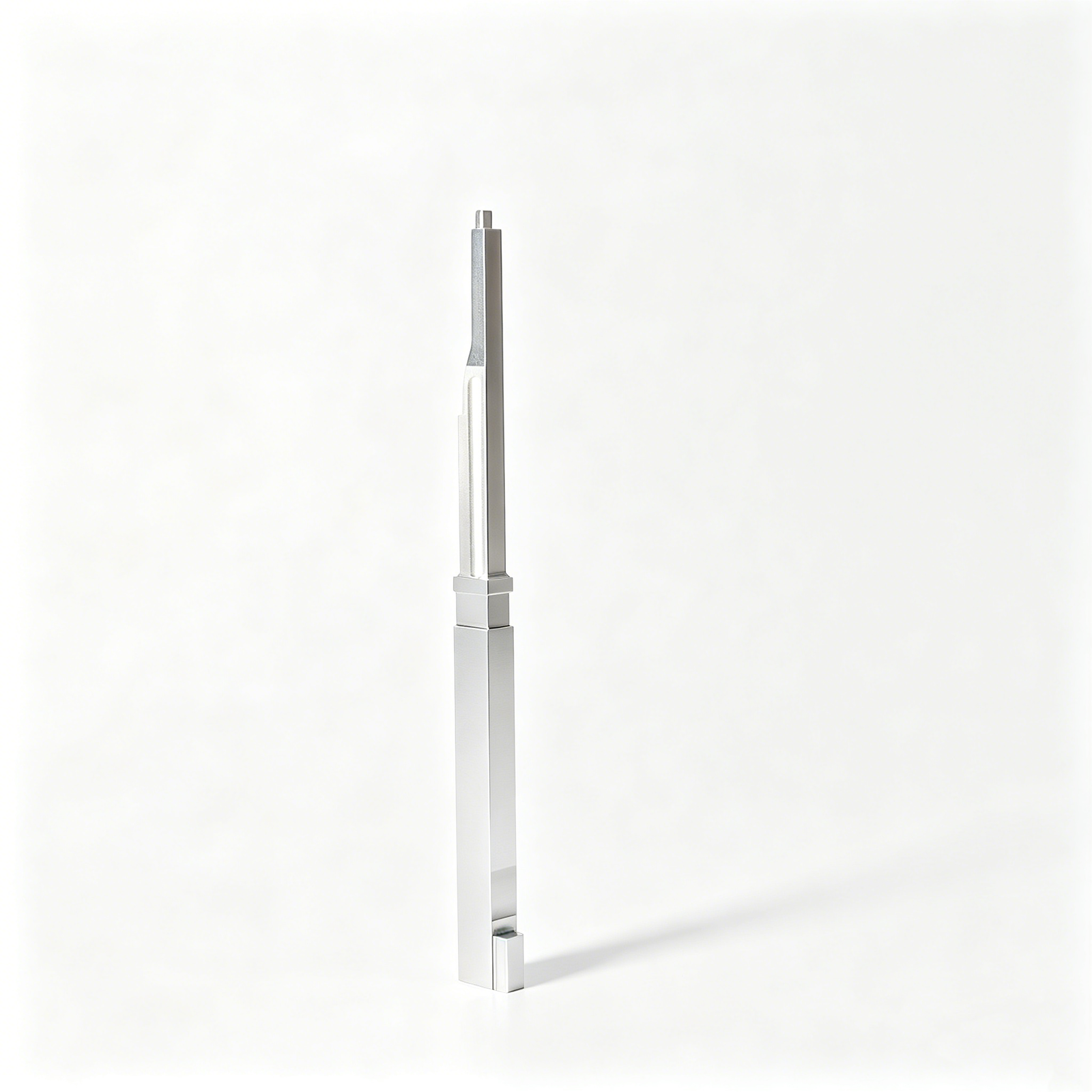
Connector Mold Components
Precision connector mold components for fine-pitch, high-density, and mating-critical tooling applications. Drawings should define critical pin or cavity geometry, datum scheme, material, finish, EDM requirements, tolerance stack, and inspection evidence needed for assembly.
Upload a Drawing
Stamping Die Components
Precision stamping die components for cutting, forming, guiding, and locating functions in die assemblies. Process planning evaluates material and hardness requirements, clearance-critical features, grinding needs, wire EDM profiles, mating relationships, and dimensional verification.
Upload a Drawing
Injection Mold Components, MIM, CIM & Overmolding Tooling
Injection, MIM, CIM, and overmolding tooling components manufactured within verified production scope. Submit the part drawing, resin or feedstock context, tool-function requirements, critical geometry, material treatment, surface expectations, and assembly interfaces for review.
Upload a Drawing
Machining Materials
CNC machining materials selected against drawing requirements, application conditions, machining behavior, heat treatment, corrosion needs, and dimensional stability. Material availability and certification or traceability needs should be confirmed for each project before production.
Upload a Drawing
Surface Finishes & Heat Treatment
Surface finishing and heat treatment planned around wear resistance, corrosion protection, hardness, appearance, dimensional change, and mating function. Specify the required process, target condition, masking needs, post-treatment grinding allowance, and acceptance criteria.
Upload a Drawing
Quality, Metrology & Documentation
Precision inspection, metrology, and quality documentation matched to the order’s critical dimensions and agreed inspection plan. Define required reports, datum references, sampling expectations, material records, revision status, and any customer-specific traceability requirements before release.
Upload a Drawing
Prototyping & Low-Volume Production
Rapid prototyping and low-volume manufacturing for drawing-based parts requiring controlled transition from review to repeatable production. Share quantity, delivery target, material, critical features, surface needs, inspection requirements, and expected revision path for an informed RFQ.
Upload a DrawingLeader Pins and Bushings Materials Matched to Your Drawing

Alloy Tool Steel
A common choice for leader pins requiring a hard, stable working surface after the specified heat-treatment route. Suitable for guided mold assemblies where drawing-defined fit, straightness, grinding stock, and wear expectations require review.

Pre-Hardened Tool Steel
Used when the project benefits from machining in a supplied pre-hardened condition and a controlled finishing plan. It can simplify selected process routes, but final suitability depends on geometry, required surface condition, and inspection criteria.

Stainless Tool Steel
Considered for tooling exposed to humid environments, corrosive molding conditions, or cleaning requirements. Material grade, heat-treatment sequence, and final finish should be confirmed against the application because corrosion resistance and machinability involve practical trade-offs.

Bearing Bronze
Often evaluated for bushing applications where controlled sliding behavior and lubrication strategy matter. The selected bronze grade should be matched to pin material, load, cycle conditions, clearance, and any cleanliness or maintenance requirements shown in the project.

Graphite Plug Bronze
A project-specific bushing option for applications considering self-lubricating features. Plug layout, contact conditions, mating-pin finish, and contamination sensitivity need engineering review before manufacture, rather than being assumed from a catalog-style material designation.
Leader Pins and Bushings Manufacturing Processes

CNC Turning
CNC turning establishes pin diameters, shoulders, reliefs, and bushing profiles from the drawing. Controlled stock is retained where later heat treatment, grinding, or EDM is required for the specified fit and finish.

CNC Milling
CNC milling produces flats, mounting features, oil grooves, and related mold-component geometry with tool access considered early. The route is reviewed against datums and mating features before machining begins.

Wire EDM
Wire EDM cuts precise profiles, slots, and non-round features where conventional tools cannot reach cleanly. Wire path, start-hole access, and finishing allowance are planned around the drawing and downstream fitting needs.

Sinker EDM
Sinker EDM supports formed details and internal geometry that need an electrode-based approach. Electrode strategy, spark allowance, surface requirement, and subsequent polishing or grinding needs are reviewed before release.


Fitting Inspection
Fitting and inspection verify functional relationships, critical dimensions, and order-specific reporting requirements. Measurement results, revision status, and any agreed inspection documentation remain aligned with the approved drawing.
Leader Pins and Bushings: Configurable Details

Shoulders and Steps
Define shoulder diameter, height, transition radii, and seating datum to support controlled mounting and axial location. SUUXIANG reviews tool access, grinding allowance, and the relationship between stepped features and critical dimensions.

Reliefs and Undercuts
Relief grooves and undercuts can provide clearance at mating faces, reduce interference, or create runout space. Include dimensions, corner requirements, and mating context so the proposed machining, EDM, or grinding route can be assessed.

Lubrication Grooves
Specify groove geometry, location, and lubrication intent when bushings require grease management. Drawing review considers wall thickness, surface finish, feature access, and whether the groove location could affect the mating component or application.

Threads and Tapers
Threads, tapped holes, puller features, and tapered transitions can be incorporated where drawing-defined. Provide thread standard, class, depth, datum references, and mating details to support manufacturability review and an appropriate inspection method.

Identification Markings
Part numbers, revision marks, cavity identifiers, or orientation marks can improve assembly and traceability. State marking method, location, character size, and legibility requirements so the feature is evaluated against material condition and finished surfaces.
About SUUXIANG Leader Pins and Bushings
SUUXIANG is the international-facing brand of Dongguan SuuXiang Precision Mold Co., Ltd., established in 2010 in Chang’an Town, Dongguan, China. We help engineering, sourcing and quality teams convert drawings and specifications into inspected leader pins and bushings, mold components, connector-tooling parts and custom CNC work.
Our production planning combines CNC milling and turning, multi-axis machining, wire and sinker EDM, precision grinding, fitting and inspection. Before quotation or production commitments, we review critical dimensions, datums, tolerance stack, material and heat-treatment requirements, machining access, and the inspection evidence required for the order.
What distinguishes SUUXIANG is disciplined coordination from drawing review through revision control and final documentation. We treat leader pins and bushings as drawing-configured tooling components, not assumed catalog items, so the process route, allowances, surface requirements and verification plan can match the actual mold application.

Leader Pins and Bushings: From Drawing Review to Inspected Parts
DFM Before Commitment
SUUXIANG reviews leader pins and bushings against the drawing, mating plates, datum scheme, critical dimensions, surface requirements, material and quantity before quotation or production commitments. The review identifies tolerance-stack and tool-access questions early, so the agreed process route reflects the functional assembly.
- Confirm functional datums and critical-to-quality dimensions
- Review pin, bushing, and plate-interface requirements
- Identify tolerance-stack and machining-access risks
- Align material, heat treatment, quantity, and delivery inputs

Machining and EDM Strategy
Process planning matches feature geometry to an appropriate combination of CNC machining, multi-axis work, wire EDM, sinker EDM and related finishing operations. For leader pins and bushings, electrode access, wire paths, hardness sequence and remaining stock are reviewed against the drawing rather than assumed from a generic route.
- Plan CNC work around accessible reference surfaces
- Assess wire-EDM and electrode requirements for detailed features
- Sequence heat treatment and finishing around dimensional priorities
- Keep process choices tied to drawing-defined functional needs

Grinding and Fitting Allowance
Grinding stock and fitting requirements are considered before final dimensions are produced. SUUXIANG evaluates the relationship between guide features, mounting conditions and mating components so that finishing work supports the specified fit and assembly intent, with allowances visible in the agreed manufacturing plan.
- Define finishing stock where grinding is required
- Review fit intent with mating-component information
- Protect critical surfaces through planned process sequencing
- Clarify assembly-sensitive dimensions before release

Inspection and Revision Control
Inspection planning follows the approved drawing and identified critical dimensions. SUUXIANG keeps revision, inspection and delivery information connected to the order, enabling buyers to define reporting expectations before production and receive documentation that corresponds to the verified inspection plan.
- Establish inspection priorities from critical dimensions
- Confirm required reports and measurement methods early
- Maintain drawing-revision visibility through production
- Match final documentation to the order requirements

Leader Pins and Bushings: SUUXIANG vs. a Generic Quote
A drawing-led workflow keeps manufacturing decisions, inspection expectations, and revision status visible before production begins.
← Swipe left or right to view →
Leader Pins and Bushings Production Workflow
A controlled project path that keeps drawing requirements, critical dimensions, process decisions and inspection expectations visible from RFQ through shipment coordination.
Review Drawing Package
Share the 2D drawing, 3D model when available, material, quantity, application and delivery target so the project team can identify missing production information early.
Confirm Critical Requirements
SUUXIANG reviews datums, critical dimensions, fits, surface requirements, heat-treatment sequence, revision status and required inspection records before quotation or production commitments are made.
Plan Process Route
The team defines practical CNC, EDM, grinding and fitting steps, including machining allowance, tool access, electrode strategy, wire path and inspection approach for the drawing.
Machine Precision Components
Leader pins and bushings are manufactured through the approved process route, with CNC machining, EDM or grinding applied where the specified geometry and access require them.
Inspect Against Requirements
Finished parts are checked to the agreed inspection plan, focusing on critical dimensions, datum relationships, surface requirements and documentation that matches the verified order revision.
Pack and Coordinate Shipment
After final review, components are prepared for delivery with order-specific documentation and shipment coordination aligned to the agreed destination, packaging needs and project schedule.
How to Source Leader Pins and Bushings
Provide complete project inputs, confirm technical priorities, and release production only after requirements are aligned.
Upload Your Drawing
Send the 2D drawing and, when available, 3D model with application context, quantity, material, heat treatment, target delivery date, and revision identification.
Define Critical Requirements
Identify critical dimensions, datums, surface requirements, inspection or reporting needs, and mating-component considerations so SUUXIANG can assess machining access, EDM strategy, grinding stock, and traceability.
Review DFM and Quote
Review the proposed process route, clarifications, quality plan, and commercial quotation. Resolve open tolerance, material, or revision questions before sample or production release.
Release Approved Production
Approve the documented requirements and any agreed sample outcome. SUUXIANG then coordinates CNC machining, EDM, grinding, fitting, inspection, and delivery updates against the released revision.
Leader Pins and Bushings Certificates and Quality Documentation

Customer Feedback Publication Policy
Pending customer approval: publish a verified quotation describing the leader pin and bushing application, inspection outcome, delivery result, and at least one confirmed project metric before using this space as a testimonial.
Pending customer approval: document the drawing revision reviewed, critical dimensions addressed, and a verified outcome such as accepted quantity, measurement result, or schedule milestone before publishing customer feedback.
Pending customer approval: include the tooling context, agreed material and process route, inspection documentation provided, and one confirmed numerical result so procurement teams can evaluate the feedback with appropriate context.
Leader Pins and Bushings FAQ
Practical answers for engineering and procurement teams preparing a drawing-based request.
Can SUUXIANG manufacture custom leader pins and bushings from my drawing?
What is the MOQ for leader pins and bushings?
How long does a custom leader pin and bushing order take?
Can I order samples or a prototype before production?
What drawings and files should I send for a quotation?
Can SUUXIANG hold the tolerances shown on my drawing?
What inspection evidence can be supplied with leader pins and bushings?
How are payment, shipping, and IP protection handled?
The Complete Buyer’s Guide to leader pins and bushings
Use this decision framework to specify fit, materials, lubrication, and quality controls; compare supplier capabilities; and avoid alignment, wear, drawing, and sourcing mistakes before production.
1. What Are leader pins and bushings?
Two hardened, ground components form the basic guidance system: a leader pin, also called a guide pin, and its mating guide bushing. Installed in the mold base or die-set plates, the pin enters the bushing during closing to bring mold halves, moving plates, or die members into controlled alignment before working surfaces meet.
0.0015–0.0025 inch total clearance is one published example of a close sliding fit; the required value must still follow the drawing, load, lubrication, contamination, and thermal conditions. Too little clearance can cause binding or galling, while excessive clearance permits impact, positional error, bushing deformation, and accelerated wear. Source: https://www.moldmakingtechnology.com/articles/what-you-need-to-know-about-leader-pins-and-bushings-2
Four terms should remain distinct in an RFQ: leader pin and guide pin describe the guiding shaft; guide bushing describes the mating bearing element; mold base describes the plate structure retaining them. Their purpose is repeatable guidance, not automatic correction of poor datum layout, plate deflection, or cavity-to-core alignment errors.
2. Evolution of Mold Guidance Systems
0.0015–0.0025 in. total clearance is a commonly cited close sliding fit for a leader pin and its bushing, reflecting the move beyond simple alignment dowels toward controlled guidance. Precision-ground mating diameters made repeatable plate location practical as tooling tolerances tightened. Source: https://www.moldmakingtechnology.com/articles/what-you-need-to-know-about-leader-pins-and-bushings-2
0.0010 in. oversize shoulders on shouldered pins enable stacked plates to be line-bored at a shared location and diameter, reducing setup mismatch in multi-plate tools. Heavier plates and long floating-plate strokes increased cantilever loading, so pin diameter, support length, and bushing engagement became design decisions rather than catalog selections. Source: https://www.ptonline.com/articles/what-you-need-to-know-about-leader-pins-and-bushings
66–70 HRC is reported for some black-nitride-treated steel bushings, illustrating a broader industry shift toward lubrication features and wear-focused surfaces for automated, high-cycle tools. Treatment choice still depends on contamination risk, maintenance access, life target, and mating materials. SUUXIANG can review these drawing-defined requirements through its CNC, EDM, grinding, fitting, and inspection workflow; acceptance remains subject to current project evidence.
3. Types of leader pins and bushings
Two pin geometries and several bushing interfaces change how a mold closes, carries plate weight, and is serviced. The configuration distinctions below follow general guidance at https://www.ptonline.com/articles/what-you-need-to-know-about-leader-pins-and-bushings.
| Configuration | Mounting | Use And Maintenance |
|---|---|---|
| Straight pin + steel bushing | Bored pin and retained bushing | General sliding guidance; plan lubrication and replacement. |
| Shouldered pin | Common through-bored location | Supports precise plate registration; define shoulder projection. |
| Bronze-lined/self-lubricating bushing | Retained or face-mounted | Specify contamination, duty cycle, and lubrication expectations. |
| Ball-bearing bushing | Purpose-designed housing | Review travel, load direction, sealing, and serviceability. |
Pin Geometry And Mounting
Straight pins typically seat in a dedicated bore; shouldered pins permit through-boring stacked plates at a common location. Specify pin diameter, working length, shoulder dimensions, retention fit, and datum relationship.
Long strokes increase cantilever loading, so plate mass, unsupported length, and required closing guidance belong on the drawing.
Bushing Interface Choices
Plain steel bushings suit lubricated sliding guidance; bronze-lined or self-lubricating versions can reduce routine lubrication demands. Ball-bearing bushings are an application-specific choice where rolling guidance, load path, contamination exposure, and travel are explicitly reviewed.
Face-mounted layouts may need die-style bushings or risers when standard engagement length is insufficient. Call out mounting face, bore depth, flange or retainer details, grease-groove location, and service access.
4. Materials for leader pins and bushings
Two decisions govern sliding life: which member is sacrificial and how contamination is controlled. Specify material, treatment, lubrication, and replacement access together on the drawing.
| Option | Strength | Watchpoint |
|---|---|---|
| Hardened tool steel | Wear resistance | Needs clean lubrication |
| Case-hardened steel | Tough core | Case depth matters |
| Bronze bearing bushing | Low friction | Wear part |
| Nitrided or coated surface | Surface hardness | Validate corrosion and lubricant compatibility |
Pair Hardness Intentionally
One sliding member should be deliberately softer or more replaceable. The softer member commonly wears or galls first; select it intentionally, then define its replacement threshold and spare-part identity.
Two hardened members can resist indentation yet become vulnerable to scuffing if lubrication fails or debris enters the fit.
Match Treatment To Environment
Three exposure factors change the choice: cycle count, moisture, and cleanliness. Hardened or case-hardened steel suits robust guided service; bronze bearing materials reduce friction and make a practical sacrificial bushing.
66–70 HRC black-nitrided bushings are reported with grease grooves, but any low-lubrication claim needs application validation.
Control Lubrication And Debris
One grease path belongs where it protects the interface without transferring lubricant toward molded parts. Confirm groove location, approved lubricant, relubrication interval, cleanroom restrictions, and inspection access before release.
Source: https://www.ptonline.com/articles/what-you-need-to-know-about-leader-pins-and-bushings describes softer-member wear and bushing grease-groove practice.
5. Custom leader pins and bushing specifications
A custom drawing should separate alignment-critical interfaces from preferences. For leader pins and bushings, define the mating diameters, installed positions, engagement length, and plate geometry before specifying cosmetic or handling details.
Define Functional Interfaces
Three interface groups drive fit: pin OD and bushing ID, mounting diameters, and shoulder or face locations. Specify datums and positional tolerances from the mold plates, not only component length.
0.0015–0.0025 in total sliding clearance is a published convention, but the required fit must follow load, contamination, temperature, and lubrication conditions. Source: https://www.moldmakingtechnology.com/articles/what-you-need-to-know-about-leader-pins-and-bushings-2
Specify Features And Treatment
45° lead-in chamfers, groove location, surface finish, heat treatment, coating, and marking need drawing callouts. Identify grease grooves on the bushing when lubricant control near molded parts matters.
One functional callout is a hardened running surface; packaging labels and corrosion protection are buyer preferences unless they affect traceability or storage life.
Send Review Inputs
Six RFQ inputs improve manufacturability review and quote accuracy.
- 2D drawing and current revision
- 3D model and quantity
- Material, hardness, coating, and finish
- Mold layout, plate thickness, and operating stroke
- Critical dimensions, inspection method, and report needs
- Application, lubricant, packaging, and target date
6. Quality Elements That Protect Alignment
Two sliding surfaces protect mold alignment only when their geometry, finish, and identification are controlled as a system. Drawing review should define measurable acceptance criteria before machining begins.
Pin Geometry And Shoulders
Specify the inspection scope for leader pins, including diameter, roundness, straightness, and concentricity to the locating or mounting feature, based on drawing-critical requirements and the agreed inspection plan.
90-degree shoulders need verified squareness to their functional axis; runout or a tilted seating face transfers load into the bushing.
Bore, Finish, And Hardness
100% of bushing bores require diameter and geometry checks, including taper, bellmouth, roundness, and axis position relative to the mounting datum.
Ra requirements, effective hardness depth, and complete edge deburring should be stated on the drawing; a sharp bore entry can score a finished pin during assembly.
Load And Traceability
3 variables—plate mass, unsupported pin length, and stroke—determine deflection risk. Long floating-plate strokes increase cantilever force; inadequate support can deform, gall, or prematurely wear bushings (https://www.moldmakingtechnology.com/articles/what-you-need-to-know-about-leader-pins-and-bushings).
1 matched set should retain part, material, heat-treatment, inspection, and revision records. Marking or controlled packaging prevents a verified pin from being paired with an unverified bushing.
7. How to Choose a Manufacturer
A 2D drawing review is the first evidence of whether a supplier can control custom, low-volume leader pins and bushings. Compare documented planning, verification, and response practices before comparing unit price.
| Evaluation Area | Ask The Supplier | Request |
|---|---|---|
| Process route | How will critical features be machined and checked? | Routing and inspection plan |
| Heat treatment | When is treatment performed relative to grinding? | Treatment record if specified |
| Delivery control | How are revisions, packing, and delays managed? | Milestone and packing plan |
Test Drawing Review Rigor
A 2D drawing review should identify datums, critical diameters, fit intent, surface requirements, and revision status before quotation.
One useful question is whether the supplier can explain the CNC, EDM, grinding, and inspection route for every critical feature.
Request Traceability Evidence
One material certificate alone is insufficient when material grade, heat treatment, and final hardness affect wear behavior.
Two documents to request are the material record and the agreed inspection report; confirm which dimensions, instruments, and acceptance criteria they cover.
Assess Project Control
One prototype or first-off plan should define revision control, delivery milestones, protective packing, and the communication owner.
Two corrective-action questions matter: how are nonconforming parts contained, and what evidence closes the action?
8. Common leader pins and bushings Mistakes
Leader pins and bushings fail most often at the drawing-review stage, not during purchase. Treat each mating pair as a guided system with a defined load, clearance, lubrication, material, and inspection basis.
Assuming Standard Parts Interchange
A nominal diameter alone does not establish interchangeability across suppliers. The symptom is assembly interference or excess play; validate pin, bushing, shoulder, mounting, and engagement dimensions as one matched drawing set.
Ignoring Clearance And Load
Clearance accumulates through pin diameter, bushing bore, plate bores, and datum location. The symptom is banging, galling, or misalignment under a long or heavy plate; review the full tolerance stack and check deflection against stroke and plate load.
Leaving Service Details Undefined
Lubrication, groove location, material, hardness, and surface requirements cannot be left to assumption. The symptoms are contaminated molded parts, premature wear, or untraceable substitutions; specify the lubrication plan, keep grease-control features away from contamination paths, and require material and heat-treatment evidence.
A drawing missing datums, critical dimensions, revision status, or inspection requirements is not production-ready. The preventive action is a pre-release drawing review with mating-component context and an agreed inspection plan.
9. Steps to Launch a Custom Tooling Project
A custom guidance-component release should pass defined decision gates before metal is cut. For international sourcing, SUUXIANG can align the drawing package, approval record, inspection expectations, and shipment plan around one controlled revision.
Build The Release Package
Revision 0 should include the 2D drawing, 3D model when available, quantity, application, mating-part details, material, heat treatment, and delivery target. Engineering owns functional datums and critical dimensions; procurement owns commercial terms and approved release timing.
Close DFM Questions
Before release, SUUXIANG should return drawing-review questions covering open tolerances, press or sliding fits, bushing-to-plate interfaces, machining access, and inspection method. A written disposition for every uncertainty prevents assumptions from becoming nonconforming parts.
Approve And Maintain Supply
First-article or sample approval should compare agreed critical dimensions and material evidence against the released revision before production proceeds. Final shipment documentation should match the inspection plan, while spare-part planning records part number, revision, mating relationship, and replacement quantity.
10. Pricing leader pins and bushings
Two quotation stages keep leader pins and bushings pricing defensible. An initial estimate can frame the process route, but a binding quote requires drawing review of datums, fit, material, heat treatment, surface, quantity, and inspection scope.
One unit price is incomplete for a tooling program. Compare total landed risk: revision clarity, matched-pin-and-bushing fit, inspection evidence, packaging, delivery coordination, and the cost of rework or schedule disruption.
| Cost driver | Relative effect | Quote review point |
|---|---|---|
| Quantity tier | Prototype highest; repeat production lower per piece | Setup recovery and release schedule |
| Diameter and length | Higher with larger or longer parts | Stock size, machining access, grinding time |
| Material and heat treatment | Higher when specified | Grade, hardness, sequence, distortion allowance |
| Grinding tolerance | Higher as tolerance tightens | Critical diameter, datum, mating clearance |
| Coating | Adds cost | Wear, lubrication, corrosion requirement |
| Inspection records | Adds cost | CTQs, report format, traceability |
| Lead time | Expediting may increase cost | Prototype urgency versus repeat scheduling |
Submit Leader Pins and Bushings Drawings for Review
Send material, heat-treatment, quantity, critical dimensions, inspection requirements, and target delivery date for a drawing-based quotation.