
Micro Connector Core Pins, From Drawing to Inspection
Submit micro connector core pins drawings for DFM-led CNC, EDM, grinding, and inspection planning aligned to your critical dimensions.
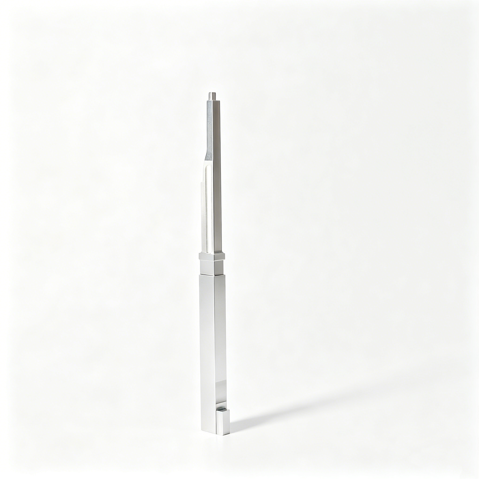
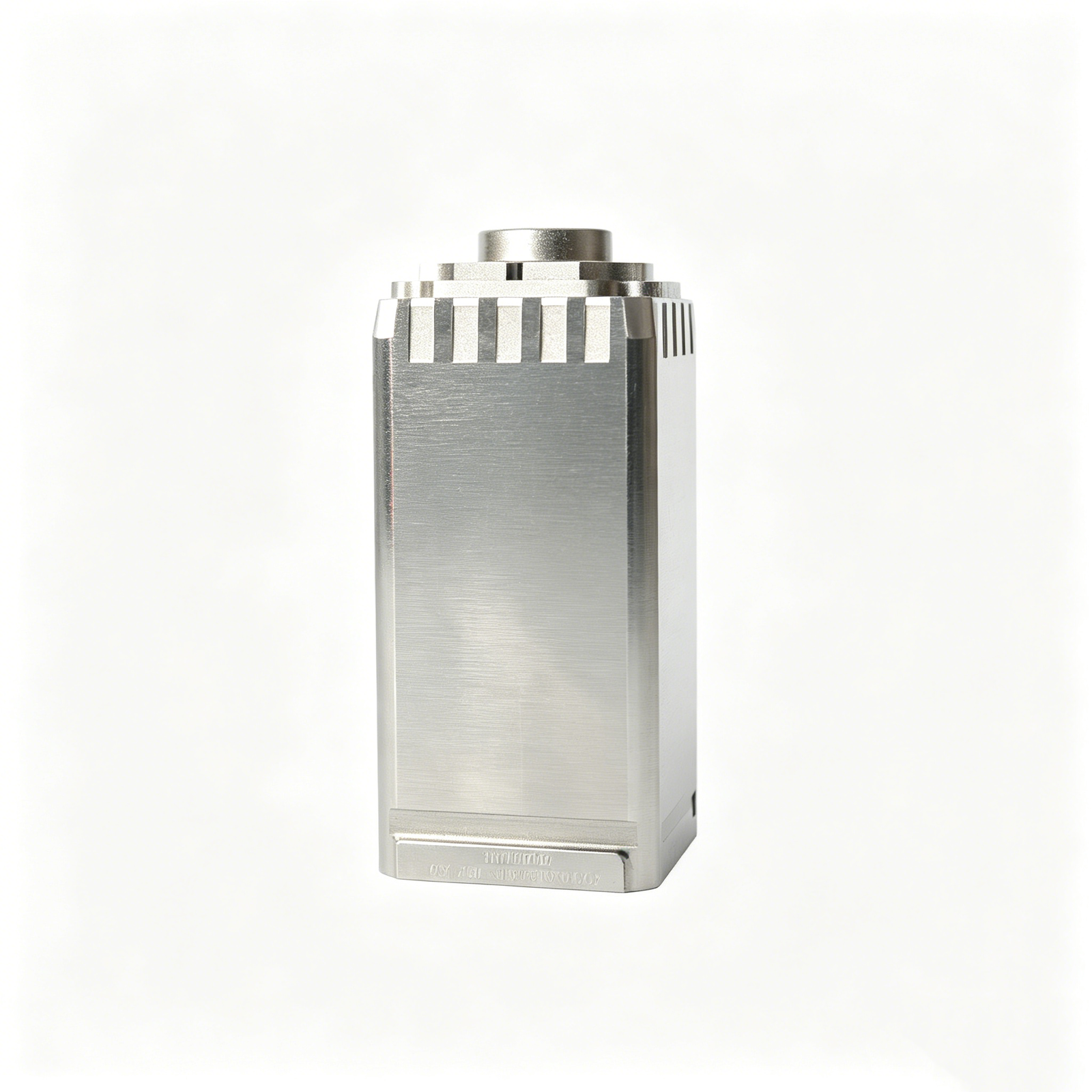
Featured Micro Connector Core Pin Configurations






Related Component Families and RFQ Support







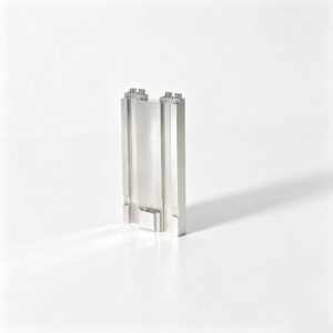
Micro Connector Core Pins, Planned From the Drawing
A disciplined review aligns DFM, process sequence and inspection expectations before production commitments.
Drawing-Led DFM Review
Review drawings, models and mating context to identify tool access, fine features, datum strategy and manufacturability questions before quotation.
Critical Dimensions First
Define critical dimensions, surfaces and functional relationships early so machining, EDM and grinding decisions support the intended connector geometry.
Process-Route Planning
Plan the appropriate CNC, wire EDM, sinker EDM, grinding and fitting sequence around material condition, feature access and required allowances.
Revision-Controlled Communication
Keep drawing revisions, open technical questions and agreed production information visible throughout the project to reduce avoidable interpretation risk.
Inspection Plan Alignment
Align measurement methods, reporting needs and acceptance criteria with the drawing so final documentation reflects the agreed inspection plan.
Micro Connector Core Pins and Tooling Families
Drawing-driven component families for connector molds and precision tooling, planned around critical dimensions, process access, inspection requirements, and controlled revisions.

CNC Machining Services
Precision CNC machining services for drawing-defined parts requiring coordinated milling, turning, EDM, grinding, fitting, and inspection. Process planning begins with material, critical dimensions, datum strategy, surface requirements, quantity, and quality documentation needs.
Upload a Drawing
CNC Milling
Custom CNC milling services for plates, inserts, housings, cavities, and complex prismatic parts. Review focuses on tool access, corner radii, clamping approach, machining allowance, datum relationships, and features that may require EDM or grinding.
Upload a Drawing
CNC Turning
Precision CNC turning services for shafts, sleeves, bushings, pins, and rotational components. Drawings are assessed for concentricity, runout, thread details, bearing fits, surface requirements, and the secondary processes needed after turning.
Upload a Drawing
5-Axis Machining
5-axis CNC machining for multi-face parts and features whose geometry benefits from reduced setups. The process route is evaluated against tool reach, fixture stability, datum transfer, surface requirements, and inspection access before production is committed.
Upload a Drawing
Swiss & Micro Machining
Swiss machining and micro machining for small-diameter pins, connector features, sleeves, and miniature rotational parts. Manufacturability review considers material condition, slenderness, critical diameters, concentricity, burr control, handling, and measurement method.
Upload a Drawing
Wire & Sinker EDM
Wire EDM and sinker EDM services for narrow slots, sharp internal geometry, hardened features, and mold details beyond conventional tool access. Electrode strategy, wire path, flushing, finish requirement, recast-layer considerations, and inspection points are reviewed.
Upload a Drawing
Precision Grinding
Precision surface and profile grinding for flatness, parallelism, profile accuracy, and controlled stock removal. Grinding plans account for heat-treatment sequence, grinding allowance, datum protection, wheel access, surface targets, and final measurement requirements.
Upload a Drawing
Mold Core & Cavity Inserts
Precision mold core and cavity inserts manufactured from customer drawings and specified materials. Planning addresses shutoff geometry, cooling or feature access, heat-treatment sequence, EDM and grinding needs, fitting interfaces, and critical dimensional verification.
Upload a Drawing
Ejector & Ejection Components
Ejector pins, sleeves, and ejection components for mold mechanisms that require controlled fit and reliable movement. Review covers diameters, clearance relationships, hardness requirements, surface condition, guide length, mating components, and inspection expectations.
Upload a Drawing
Core Pins, Guide & Locating Components
Core pins, guide pins, and locating components produced to drawing-defined dimensions and mating requirements. Critical considerations include pin geometry, concentricity, fit class, wear surfaces, heat treatment, grinding strategy, and datum relationships across assemblies.
Upload a Drawing
Slides, Lifters, Gates & Mold Accessories
Mold slides, lifters, gates, and accessories for configurable tooling assemblies. Manufacturing review considers travel interfaces, angular or sliding surfaces, shutoffs, wear points, fit-up requirements, machining access, heat-treatment sequence, and assembly-level inspection.
Upload a Drawing
Connector Mold Components
Precision connector mold components for fine-pitch cavities, inserts, pins, and related tooling details. Process planning emphasizes critical pitch and alignment features, small geometry, EDM or grinding requirements, burr control, mating-component context, and traceable revisions.
Upload a Drawing
Stamping Die Components
Precision stamping die components including punches, dies, guide elements, inserts, and custom wear parts. Drawing review addresses material and heat treatment, cutting-edge geometry, clearance relationships, grinding stock, EDM requirements, and inspection criteria.
Upload a Drawing
Injection Mold Components, MIM, CIM & Overmolding Tooling
Tooling and component work associated with injection molding, metal injection molding, ceramic injection molding, and overmolding, when within verified production scope. Discussions identify material flow-related geometry, critical interfaces, finish needs, tool access, and validation documentation.
Upload a Drawing
Machining Materials
CNC machining materials selected against the drawing, application, heat-treatment requirement, corrosion exposure, wear condition, and downstream process route. Material availability and certification needs should be confirmed before quotation and production planning.
Upload a Drawing
Surface Finishes & Heat Treatment
Surface finishing and heat treatment planned as part of the manufacturing sequence, not as an afterthought. Requirements for hardness, coating, corrosion resistance, texture, grinding allowance, dimensional change, masking, and verification should accompany the RFQ.
Upload a Drawing
Quality, Metrology & Documentation
Precision inspection, metrology, and quality documentation aligned to the approved drawing and inspection plan. Buyers can define critical dimensions, datum references, sampling expectations, report format, material records, revision status, and any required traceability.
Upload a Drawing
Prototyping & Low-Volume Production
Rapid prototyping and low-volume manufacturing for drawing-driven parts requiring practical process selection before wider release. Supply the model, drawing, material, quantity, critical features, quality needs, and delivery target so feasibility and inspection requirements can be assessed.
Upload a DrawingEngineering Materials for Micro Connector Core Pins

Tool Steels
A practical starting point for many micro connector core pins and mold inserts, selected for balanced machinability and post-treatment planning. Grade, hardness target, grinding allowance, and final inspection criteria should be defined per drawing.

High-Speed Steels
Often considered where fine features and wear-sensitive tooling demand a robust process route. Material condition, heat-treatment sequence, EDM strategy, and finish-grinding stock require review against the part geometry and expected service conditions.

Stainless Tool Steels
Considered for precision components where corrosion resistance is relevant alongside dimensional control. The selected grade, heat treatment, surface condition, and mating environment should be confirmed during DFM and critical-dimension review.

Tungsten Carbide
A candidate for highly wear-sensitive, small-feature applications when brittleness, geometry, and machining access can be managed. SUUXIANG reviews grinding approach, EDM requirements, datum control, and inspection method before confirming suitability.

Copper Alloys
Used for selected electrodes and tooling-related components where electrical or thermal behavior informs the manufacturing route. Alloy selection, electrode detail, finish requirements, and dimensional priorities should be supplied with the RFQ.
Manufacturing Processes for Micro Connector Core Pins


Wire EDM
Wire EDM creates narrow slots, fine profiles, and internal geometry where cutter access is limited. Wire-path planning, start-hole location, and datum relationships are reviewed against the drawing before machining.

Sinker EDM
Sinker EDM forms deep cavities, sharp internal details, and difficult-to-reach features using a planned electrode strategy. Electrode wear, flushing access, and finishing requirements are considered during process review.


Fitting and Inspection
Fitting and inspection confirm functional relationships between micro connector core pins and mating tooling features. Measurement methods, critical dimensions, revision status, and required reporting are aligned with the order requirements.
Micro Connector Core Pins: Supported Features

Locating Features
Datum-driven locating flats, shoulders, and reference features help establish repeatable orientation during mold assembly and inspection. Provide mating-part context and critical relationships so the feature can be reviewed for machining access and tolerance stack.

Gate Details
Gate-adjacent pin geometry can be planned around flow-path, shutoff, and wear considerations. Identify gate type, resin or molding context, surface priorities, and revision-controlled dimensions before the manufacturing route is confirmed.

Slide Interfaces
Slide-facing profiles, reliefs, and shutoff interfaces require clear datum references and assembly context. SUUXIANG reviews these details for tool access, EDM or grinding needs, fitting allowance, and inspection points before production.

Guide Elements
Guide bores, lead-ins, and locating interfaces support controlled alignment between moving or mating tooling elements. Define the functional datum scheme, fit requirement, mating material, and inspection method with the drawing package.

Ejector Interfaces
Ejector-facing contact areas, clearance features, and retention details can be incorporated where the application requires them. Share ejection layout, load-sensitive surfaces, and assembly constraints to support a practical process and inspection plan.

Identification Marks
Part numbers, revision marks, cavity identifiers, and orientation references can improve traceability during fitting, inspection, and maintenance. Specify marking content, position, visibility, and any surface restrictions directly on the controlled drawing.
About SUUXIANG
SUUXIANG is the sole public-facing brand of Dongguan SuuXiang Precision Mold Co., Ltd., established in 2010 in Chang’an Town, Dongguan, Guangdong, China. XiaoCheng Huang is the founder and legal representative. We help international engineering and sourcing teams turn drawings, models, and quality requirements into inspected precision mold components, custom CNC parts, and connector-tooling work.
For micro connector core pins and related tooling components, our process planning can combine CNC milling and turning, multi-axis machining, EDM, precision grinding, fitting, and inspection. Before quotation or production commitments, we review critical dimensions, datums, material and heat-treatment requirements, tool access, and inspection expectations.
Our difference is disciplined project control: DFM discussion before release, an appropriate process route for the geometry, visible revision handling, and documentation aligned with the verified inspection plan. Buyers receive a technical manufacturing conversation focused on the evidence needed to make the part correctly.

Core Capabilities for Micro Connector Core Pins
Drawing-Led DFM Review
Before quotation, SUUXIANG reviews micro connector core pins against the drawing, 3D model, mating geometry, datums, critical dimensions, material requirements, and surface expectations. The review identifies tool-access limits and manufacturing decisions that should be resolved before production commitments.
- Confirm critical-to-quality features and datum strategy
- Review tolerance stack and mating-component context
- Identify machining access and feasible process routes
- Align revision, quantity, delivery, and reporting requirements

CNC and EDM Strategy
Fine profiles, narrow gaps, and difficult internal details often require a planned sequence of CNC machining, wire EDM, sinker EDM, and secondary operations. SUUXIANG selects the route according to geometry, material condition, electrode needs, wire path, and required finishing allowance.
- Plan roughing and finishing around feature access
- Assess wire paths for fine slots and profile details
- Define electrode strategy for EDM-reachable geometry
- Preserve stock for downstream grinding or fitting

Grinding and Fitting Control
For micro connector core pins, grinding is planned as a controlled finishing step rather than an afterthought. Allowance, datum transfer, contact surfaces, and assembly relationships are reviewed so finished geometry can support the intended mold function and practical fitting work.
- Set grinding stock before final process sequencing
- Control reference surfaces through finishing operations
- Review contact, locating, and assembly interfaces
- Escalate drawing ambiguities before final fitting

Inspection and Revision Traceability
Inspection planning follows the agreed critical dimensions, datum references, surface requirements, and reporting needs. SUUXIANG keeps drawing revisions, inspection expectations, and delivery coordination visible throughout the project, so the final documentation corresponds to the ordered micro connector core pins.
- Match measurement methods to critical features
- Record inspection requirements before production release
- Maintain drawing-revision visibility through the project
- Coordinate documentation with the verified inspection plan

Why Choose SUUXIANG for Micro Connector Core Pins?
For drawing-based micro connector core pins, SUUXIANG prioritizes reviewable process decisions and order-specific evidence.
← Swipe left or right to view →
Production Workflow for Micro Connector Core Pins
Each project follows a documented route from drawing review through inspection and shipment coordination, with process choices confirmed against the order requirements.
Review Drawings and DFM
Review 2D and 3D files, critical dimensions, datums, surface requirements, mating context, quantity, and inspection expectations before quotation or production commitments.
Plan Material and Process
Confirm material and heat-treatment requirements, then define machining access, EDM strategy, grinding stock, workholding, and the sequence needed for the specified geometry.
Machine Critical Features
Produce micro connector core pins through the appropriate CNC, multi-axis, Swiss machining, wire EDM, sinker EDM, and precision grinding operations for the drawing.
Fit and Verify Dimensions
Perform fitting where required and inspect agreed critical features using the order-specific inspection plan, maintaining revision visibility throughout the manufacturing route.
Pack and Coordinate Shipment
Match final documentation to the verified inspection plan, protect finished components for transit, and coordinate delivery information with the customer’s project schedule.
Start Your Micro Connector Core Pins RFQ
Provide the engineering inputs needed for a disciplined drawing review, manufacturability discussion, and quotation.
Upload Your Drawings
Send the current 2D drawing and available 3D model, including revision status, application context, and mating-component details that affect tool access or geometry.
Define Material and Quantity
Specify required material, heat treatment, quantity, prototype or production intent, and any approved alternatives so the proposed process route aligns with your requirements.
Identify Critical Dimensions
Mark critical-to-quality dimensions, datums, surface requirements, tolerance priorities, and functional interfaces for micro connector core pins before DFM and quotation review.
Confirm Quality and Delivery
State inspection or reporting needs, traceability expectations, packaging requirements, target delivery date, and any project constraints requiring review before production commitments.
Quality Documentation and Certification Status
Micro Connector Core Pins: Customer Project Feedback and Case Evidence
Approved customer testimonial pending. Publish only after the customer confirms the project outcome, measurable result, quote wording, attribution, and permission to share the information publicly.
Documented case evidence pending. Include the drawing revision, inspection scope, quantity, delivery context, and verified result before presenting this project as a SUUXIANG customer outcome.
Customer feedback pending verification. Any future testimonial should identify the approved speaker, organization, application context, and specific measured outcome without disclosing confidential connector-tooling details.
Micro Connector Core Pins FAQ
Practical answers for drawing-based connector tooling inquiries, from DFM review through inspection and delivery coordination.
What information should I send for a micro connector core pins RFQ?
Is there an MOQ for custom micro connector core pins?
Can I order samples before placing a larger tooling order?
When are CNC machining, EDM, and grinding used for these parts?
What inspection report can I request with micro connector core pins?
How are delivery dates coordinated for custom connector tooling components?
How do payment and shipping work for an international order?
How do you manage IP, drawing revisions, and change control?
The Complete Buyer’s Guide to micro connector core pins
Use this decision framework to specify micro connector core pins, compare materials and manufacturing controls, assess capable suppliers, prevent costly tooling failures, and plan a drawing-led sourcing program with confidence.
1. What Are micro connector core pins?
2D drawings define micro connector core pins as precision mold components that create small connector cavities, terminal passages, alignment features, and other fine internal geometry during molding. They are tooling parts, not the finished connector’s conductive electrical contacts.
4 critical relationships typically govern whether a pin performs as intended: feature size and location, surface condition, concentricity to its locating diameter, and repeatable fit in the mating insert or plate. Variation in any of these can affect molded-part mating, flash risk, ejection behavior, wear, and unplanned tool maintenance.
1 complete RFQ should identify the pin’s material and heat-treatment requirement, datums, critical dimensions and tolerances, surface callouts, mating features, quantity, and revision level. Include the 3D model when available, plus application context that clarifies molding direction, tool access, inspection method, and replacement interchangeability.
2. Evolution of Connector Micro-Tooling
Two forces drive modern connector micro-tooling: miniaturized electronics and higher-density interconnect layouts. As pitch and feature spacing decrease, a small positional shift can affect cavity alignment, shutoff behavior, molding consistency, and mating performance; denser layouts also increase the cost of an isolated defect.
Four linked disciplines—CNC machining, precision grinding, EDM, and inspection—have changed the sourcing discussion. Buyers now need to define datums, critical dimensions, tool access, wire paths or electrode strategy, grinding stock, and the measurement method before a process route can be reviewed.
One legacy assumption is that a pin can be purchased mainly by nominal diameter and length. Fine-feature tooling instead requires revision-controlled drawings, material and heat-treatment requirements, wear expectations, cavity-count context, and acceptance criteria, because process sequence and verification evidence can be as consequential as the finished dimension.
3. Types of micro connector core pins
Six recurring designs cover most connector cavities, terminal slots, datum holes, and retention details. Select the pin from the molded feature and its release direction, then confirm the process route during drawing review.
| Type | Forms | Main Risk | Prefer When |
|---|---|---|---|
| Straight cylindrical | Round bore | Bending | Simple through-hole |
| Stepped shoulder | Bore and land | Shoulder stress | Two diameters align |
| Profiled or blade | Keyed hole or slot | Chipping or flash | Non-round cavity |
| Ejector or assembly | Release feature or combined detail | Mismatch | Ejection or serviceability matters |
Round And Shoulder Pins
Straight cylindrical pins form round terminal holes and small alignment bores; diameter, unsupported length, and venting clearance govern deflection risk. Choose stepped or shoulder pins when one core must form a bore plus a counterbore or locating land.
Shoulder transitions concentrate stress and require controlled radii or relief. Precision grinding is usually preferred for round shanks and concentric shoulders.
Profiled And Blade Cores

Profiled-tip pins form keyed holes, chamfers, lead-ins, and asymmetric contact cavities; sharp internal corners may require EDM. Choose blade or rectangular pins for slots, thin walls, and flat terminal passages.
Blade cores can twist, chip, or flash at the parting interface. Use EDM for fine profiles and grinding for parallel faces, with guidance matched to the thin dimension.
Ejector And Assembly Cores
Ejector-integrated pins form a feature while assisting part release, so stroke, return position, and witness marks must be specified. Choose them only when the ejection load does not threaten a delicate molded wall.
Multi-feature or assembly-based cores combine several details where a single pin cannot be machined or serviced reliably. Alignment treatment and datum-controlled fitting prevent mismatch between assembled elements.
4. Materials for micro connector core pins
Four material families cover most micro connector core pins decisions. Selection balances resin wear, pin stiffness, polish requirement, heat-treatment distortion, planned maintenance, and the supplier’s verified process route.
| Family | Wear And Polish | Toughness And Corrosion | Heat Treatment And Machining | Relative Cost |
|---|---|---|---|---|
| P20 pre-hardened steel | Moderate; good polish | Moderate; corrosion-prone | Stable; readily machined | Low |
| H13 hot-work steel | Moderate; good polish | High; corrosion-prone | Harden after machining | Medium |
| M2 high-speed steel | High; good polish | Moderate; corrosion-prone | Heat treatment needs control | Medium |
| Cemented carbide | Very high; polish varies | Low toughness; corrosion-resistant | Grinding and EDM-intensive | High |
Compare Material Families
P20 and H13 families offer balanced choices for many molded connector details.
M2 and carbide move toward wear resistance, while toughness and machining latitude change.
Match The Application
Small diameters and long unsupported lengths prioritize fracture resistance and deflection control over nominal hardness.
High-volume abrasive-resin tools may justify higher wear resistance; maintenance access can favor a tougher, replaceable pin.
Lock The Specification
Final grade and hardness must follow the drawing, resin and molding conditions, expected cycles, and supplier process capability.
Before release, confirm heat-treatment sequence, grinding stock, finish target, inspection method, and replacement strategy.
5. Surface Treatments and Custom Features
2D drawing callouts determine whether a micro core pin releases cleanly and can be measured repeatably. Specify functional geometry first; cosmetic decoration has little value on internal mold components.
| Feature | Primary Effect | Drawing Requirement |
|---|---|---|
| Tip radius | Demolding and wear | Profile and datum |
| Vent flat | Gas escape and flash | Width, depth, direction |
| Coating | Friction and corrosion | Masked zones and final size |
Tip And Vent Geometry
Diameter, tip radius, flats, and grooves need profile dimensions tied to datums. Reliefs limit rubbing and ease polishing.
Vent flats need width, depth, exit direction, and flash limit. They influence gas escape, demolding, and inspection.
Shank And Identification
Shank diameter, seating length, shoulder, and orientation control location. Define the mating-bore datum and assembly clearance.
Identification belongs outside bearing surfaces. State mark content, location, and method.
Functional Finish Requirements
Surface finish must be assigned by functional zone, not a blanket polish callout. Release direction can alter friction and demolding.
Specify treatment, masked zones, and post-process dimensions. Verify wear, corrosion, and finish after treatment.
- Include 2D drawing and 3D model
- Identify CTQ dimensions and datums
- State material and heat treatment
- Define finish, coating, and masked areas
- Name inspection method and revision
6. Quality Controls for micro connector core pins
Each lot should be linked to the ordered material, heat-treatment condition, drawing revision, and inspection plan. For micro connector core pins, acceptance must convert every critical feature into a measurable requirement.
Dimensional Control
Diameter, straightness, concentricity, and runout need defined datums and measurement locations. A nominal diameter alone cannot control a long, slender pin or a stepped tip.
Connector pitch accumulates pin position, insert location, and cavity tolerances. Review the complete stack-up against the mating insert before releasing limits.
Tip And Surface Acceptance
Tip radius, edge break, burr condition, and surface finish should be called out where they affect polymer flow or cavity release. Visual inspection alone is insufficient when a burr can alter a fine feature.
Heat-treatment records should identify the specified condition and lot. Inspect tip geometry after finishing, because grinding or EDM can change the functional edge.
Inspection Evidence
First-article approval should identify measured features, instruments, datums, sample quantity, and acceptance limits. Request actual values rather than a simple pass result for critical-to-quality dimensions.
Sampling rules should distinguish 100% checks from lot sampling and define disposition of nonconforming parts. SUUXIANG can align inspection reporting with the drawing and agreed verification plan before production.
- Confirm measurement method and resolution.
- Specify critical dimensions and datum scheme.
- Approve first-article records before release.
7. Choosing a micro connector core pins Supplier
Two candidate suppliers should receive the same controlled drawing package. Their responses should show how critical dimensions, datums, fine features, inspection, and delivery risks are understood before quotation.
| Evaluation Area | Evidence To Request | Risk Signal |
|---|---|---|
| Fine features | Process route and inspection method | Generic capability statement |
| Prototype transfer | Traveler and revision control | Separate undocumented setup |
| Delivery | Milestone plan and packaging detail | Single promised date |
Review Technical Evidence
One drawing review should identify tool access, EDM or grinding route, datum conflicts, and measurement method.
Two material records should link the ordered grade, heat-treatment route, hardness requirement, and part lot.
- Marked-up DFM response
- Material traceability
- Inspection-plan sample
Validate Production Control
One prototype order should use the proposed production traveler, inspection plan, revision rules, and packaging method.
Two revision checkpoints should confirm that model, drawing, inspection report, and shipment documents carry matching revision identifiers.
- First-article report
- Controlled revision log
- Protective export packaging
Test Communication Response
One risk-sensitive RFQ should receive named assumptions, open questions, and a realistic lead-time breakdown.
Two corrective-action examples should show containment, root-cause analysis, corrective action, and effectiveness verification rather than a capability claim.
- Written schedule assumptions
- Export-document checklist
- Corrective-action example
8. Common Buyer Mistakes and Prevention
Two early decisions drive much of the avoidable rework: the datum scheme and functional tolerance rationale. Release them before process planning, not after a first sample exposes a stack-up problem.
Datums And Functional Tolerances
One incomplete datum scheme lets machining and inspection reference different surfaces, causing apparent nonconformance or unusable fit. Prevention: identify primary, secondary, and tertiary datums on the drawing.
One blanket tight tolerance increases EDM, grinding, and inspection effort without improving function. Prevention: tie each critical limit to clearance, retention, or electrical mating need.
Geometry, Material, And Finish
One long unsupported pin can deflect during machining or molding, risking breakage, flash, or variable cavity geometry. Prevention: provide free length, support conditions, and allowable deflection context.
One lowest-price material choice or omitted finish callout can shorten wear life, alter release behavior, or require remake. Prevention: specify material, heat-treatment sequence, surface requirement, and mating-component stack-up.
Evidence And Revision Control
One sample approval without dimensioned measurement data accepts an unverified condition and can move scrap risk into production. Prevention: approve against the drawing, datum plan, and agreed inspection report.
One undefined revision owner permits mixed files, obsolete electrodes, and delivery delays. Prevention: name the release authority and require a controlled revision identifier before manufacture.
9. From Drawing to Production Release
One controlled release begins with the latest 2D drawing, native or neutral 3D CAD, and a revision identifier. For replacement micro connector core pins, include the mating-tool context and failure history.
Assign Functional Ownership
Engineering marks critical-to-function tip geometry, datums, shutoff relationships, and allowable feature changes.
Quality defines inspection methods, reporting format, sampling expectations, and acceptance criteria before quotation.
- Procurement confirms quantity, commercial terms, and delivery target
- Program team owns milestone dates and revision communication
Close The DFM Review
A documented DFM review checks tool access, wire path, electrode strategy, grinding stock, and heat-treatment sequence.
SUUXIANG should return open points against the controlled revision; no assumption becomes a production requirement until resolved.
Release With Evidence
First-article approval compares the agreed dimensions and required records with the released drawing.
Pilot tooling trials then confirm molding function; engineering documents changes, while procurement and quality set replenishment or maintenance triggers tied to wear, rejects, or revision release.
10. micro connector core pins Pricing
Four RFQ tiers help frame cost before a drawing review: prototype, low-volume, repeat production, and urgent replacement. Unit price usually falls as setup, programming, electrodes, and inspection planning are spread across more accepted parts.
One binding quotation requires the current 2D drawing and, when available, a 3D model, material and heat-treatment callouts, critical dimensions, finish, quantity, and delivery target. Geometry, tolerance, surface requirements, and reporting scope can change the process route materially.
Two quotes should be compared beyond unit price: confirm the revision, datum interpretation, process assumptions, inspection method, documentation, accepted yield basis, and delivery commitment. SUUXIANG should review these inputs before confirming price or lead time.
| RFQ tier | Typical quantity effect | Primary cost drivers | Lead-time effect |
|---|---|---|---|
| Prototype | Setup dominates | Complex geometry, tight tolerance, full inspection | Schedule depends on process route |
| Low-volume | Setup shared | Material, EDM/grinding, finishing | Plan capacity early |
| Repeat production | Unit cost can stabilize | Revision control, inspection sampling | Release forecast helps |
| Urgent replacement | Expedite may apply | Material availability, priority routing | Confirm feasibility first |
Upload Your Micro Connector Core Pins Drawing
Include the drawing, material, quantity, critical dimensions, inspection requirements, and target delivery date for a responsible DFM review and quotation.