
Mold Angle Pins From Drawing to Inspection
SUUXIANG reviews mold angle pins for critical dimensions, DFM, machining access, and inspection requirements before production planning.
Representative Mold Components for Angle-Pin Tooling
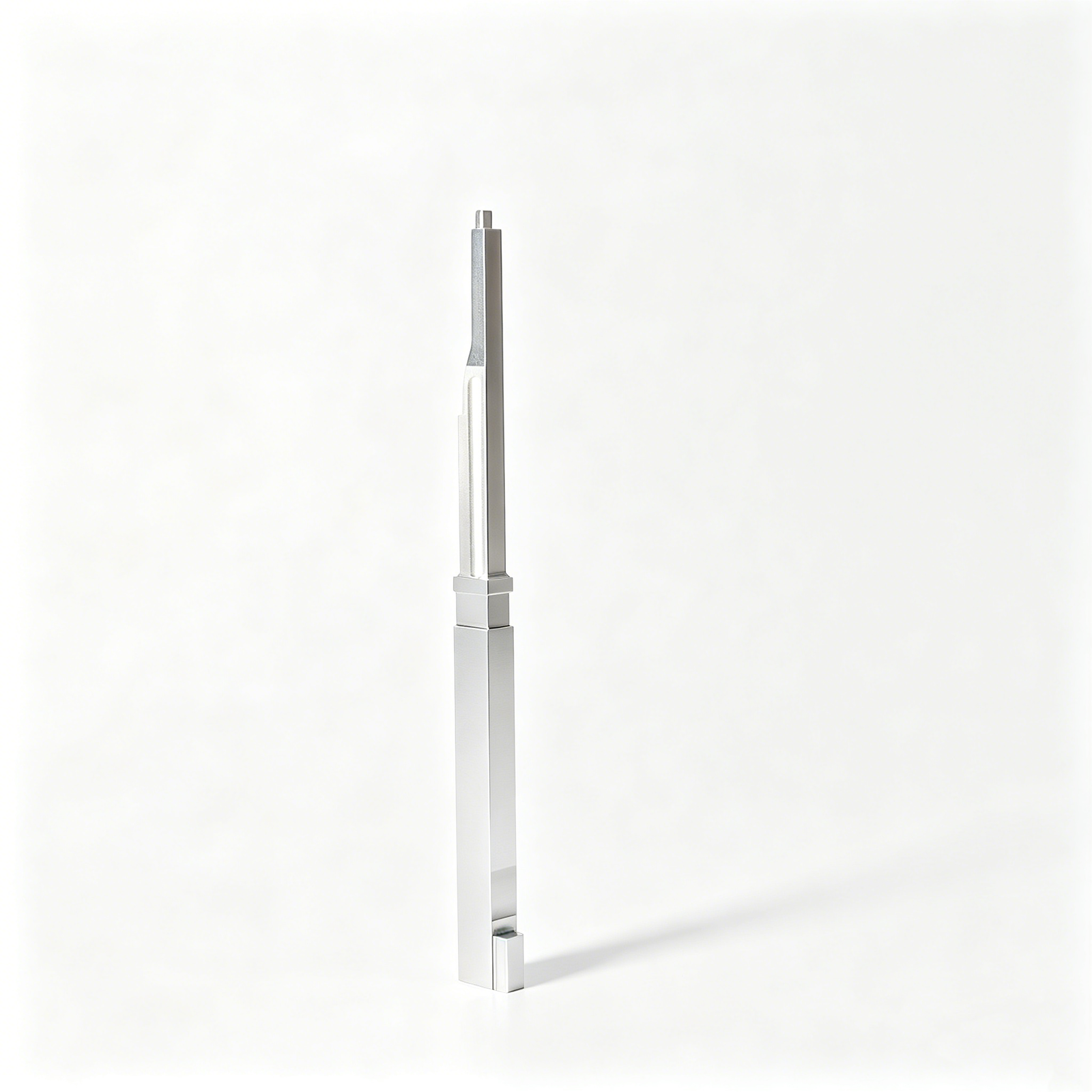


Related Mold Components and Drawing-Based Quotations





Mold Angle Pins: Engineering Advantages for Drawing-Based Sourcing
A disciplined review path for custom angle-pin and slide-mechanism components, from manufacturability decisions through inspection planning.
Drawing-Led DFM Review
Review critical dimensions, datum references, tool access, slide travel, and mating conditions before quotation or production commitments are made.
Integrated Process Planning
Plan CNC machining, EDM, grinding, fitting, and inspection as one controlled route for mold angle pins and related components.
Critical Dimension Alignment
Identify functional diameters, angles, contact surfaces, and interface features so measurement priorities reflect the mechanism’s intended operation.
Material Sequence Review
Confirm material, heat-treatment sequence, machining allowance, and surface requirements early to avoid preventable rework during downstream finishing.
Revision-Controlled Communication
Keep drawing revisions, clarifications, inspection expectations, and delivery information visible throughout project coordination for clearer sourcing decisions.
Inspection Plan Matching
Align inspection methods and requested reporting with the approved drawing, critical features, and order-specific quality requirements before final release.
Mold Component Families We Support
Drawing-driven component families and process routes for mold, connector, die, and custom precision-part requirements.

CNC Machining Services
Precision CNC machining services begin with drawing review, material, critical dimensions, and inspection requirements. Process planning may combine milling, turning, EDM, grinding, fitting, and documented inspection according to the part geometry and production scope.
Upload a Drawing
CNC Milling Services
Custom CNC milling services support prismatic mold components, inserts, plates, slides, and custom parts. Drawing review considers datum selection, cutter access, internal corners, machining allowance, surface requirements, and features that may require EDM or subsequent grinding.
Upload a Drawing
CNC Turning Services
Precision CNC turning services support rotational components such as pins, sleeves, bushings, locating features, and custom shafts. Quotation review should define diameters, runout, datum references, thread requirements, material condition, surface priorities, and inspection methods.
Upload a Drawing
5-Axis Machining
5-axis CNC machining supports complex features where multi-face access, compound angles, or reduced setups affect dimensional control. The process route is evaluated against tool reach, fixture strategy, critical datums, surface requirements, and any EDM or grinding operations needed afterward.
Upload a Drawing
Swiss & Micro Machining
Swiss machining and micro machining support small, detailed turned components where feature size, concentricity, material behavior, and handling require close review. Share drawings, quantities, critical dimensions, and inspection expectations so the appropriate production route can be assessed.
Upload a Drawing
Wire & Sinker EDM
Wire EDM and sinker EDM services address sharp internal corners, narrow slots, hardened materials, intricate profiles, and features inaccessible to cutting tools. Electrode design, wire path, recast-layer considerations, flushing, datum control, and finishing requirements should be agreed before production.
Upload a Drawing
Precision Grinding
Precision surface and profile grinding is used where flatness, parallelism, profile control, surface condition, or final-size control matters. A drawing review should establish grinding stock, heat-treatment sequence, datum references, measurement method, and critical surfaces.
Upload a Drawing
Mold Core & Cavity Inserts
Precision mold core and cavity inserts are supplied as configurable, drawing-based components rather than catalog SKUs. Review includes steel grade, heat treatment, parting geometry, cooling or feature access, EDM requirements, grinding stock, critical dimensions, and inspection documentation.
Upload a Drawing
Ejector & Ejection Components
Ejector pins, sleeves, and ejection components are evaluated for fit, stroke-related function, material condition, surface requirements, and mating-part relationships. Provide dimensions, tolerances, hardness requirements, quantity, and any application details that influence manufacturability.
Upload a Drawing
Core Pins, Guide & Locating Components
Core pins, guide pins, and locating components require attention to datum strategy, fit relationships, wear surfaces, concentricity, and heat-treatment sequence. SUUXIANG reviews the drawing and mating context to establish a suitable machining, grinding, and inspection route.
Upload a Drawing
Slides, Lifters, Gates & Mold Accessories
Mold slides, lifters, gates, and accessories are produced to drawing-defined geometry, fit, and movement requirements. Useful RFQ inputs include mating components, travel or interference context, material and heat treatment, critical sliding surfaces, and inspection priorities.
Upload a Drawing
Connector Mold Components
Precision connector mold components support fine-pitch and geometry-sensitive tooling requirements within verified production scope. Drawing review focuses on critical feature relationships, micro-scale details, material condition, EDM strategy, grinding needs, mating interfaces, and inspection planning.
Upload a Drawing
Stamping Die Components
Precision stamping die components are assessed around profile accuracy, punch-and-die relationships, material and heat-treatment requirements, wear surfaces, clearance-related features, and assembly datums. Production planning may combine machining, EDM, grinding, fitting, and documented inspection.
Upload a Drawing
Injection, MIM, CIM & Overmolding Tooling
Injection, MIM, CIM, and overmolding tooling work is considered when requirements fall within verified production scope. Submit the component drawing, application context, material, shrinkage or mating considerations, critical surfaces, quantity, and quality expectations for review.
Upload a Drawing
Machining Materials
CNC machining materials are selected from the drawing and application requirements, not assumed from a generic list. State the specified grade, condition, hardness or heat-treatment needs, corrosion or wear considerations, and any material-certification or traceability requirements.
Upload a Drawing
Surface Finishes & Heat Treatment
Surface finishing and heat treatment are planned around function, material condition, dimensional change, wear, corrosion resistance, and appearance requirements. Define the required process, coverage areas, masking needs, finish targets, post-treatment grinding allowance, and reporting expectations.
Upload a Drawing
Quality, Metrology & Documentation
Precision inspection, metrology, and quality documentation are planned around the order’s critical dimensions, datums, tolerances, and reporting requirements. Specify inspection methods, sampling expectations, first-article needs, material records, revision status, and required documentation before production.
Upload a Drawing
Prototyping & Low-Volume Production
Rapid prototyping and low-volume manufacturing support drawing-based evaluation, pilot builds, replacement components, and controlled production runs. Provide current revision files, quantity, material, critical dimensions, surface requirements, delivery target, and inspection needs for a practical review.
Upload a DrawingMaterials for Mold Angle Pins and Related Components

Pre-Hardened Tool Steel
A practical option for mold angle pins and supporting components when balanced machinability and stable dimensional control are required. The drawing review should define hardness condition, contact surfaces, grinding stock, and the expected operating cycle.

Through-Hardening Tool Steel
Considered for components that require higher core strength and wear resistance after heat treatment. Machining allowance, distortion risk, final grinding operations, and critical diameters should be agreed before the heat-treatment sequence is released.

Hot-Work Tool Steel
Selected conditionally where repeated thermal exposure or demanding mechanical loading affects component life. Material grade, heat-treatment specification, surface condition, and mating-slide requirements should be reviewed with the drawing rather than assumed from application name alone.

Stainless Tool Steel
A conditional choice where corrosion resistance, storage environment, or molded-material considerations influence the component specification. The RFQ should identify required hardness, surface finish, dimensional priorities, and whether EDM or precision grinding is needed.

Carburizing Alloy Steel
Used selectively when a hard wear surface and tougher supporting core are relevant to the design. Case-depth requirement, heat-treatment route, post-treatment finishing, and inspection method must be defined before manufacturing commitments are made.
Mold Angle Pins: Supported Manufacturing Processes


Wire EDM
Wire EDM supports narrow slots, precise profiles, and hardened-section geometry where conventional cutter access is limited. The wire path, start holes, corner conditions, and required stock for subsequent fitting or grinding should be defined from the drawing.

Sinker EDM
Sinker EDM may support internal details, formed features, or complex geometry that is impractical to mill directly. Electrode strategy, spark allowance, surface expectations, and post-EDM finishing requirements are considered during DFM review.


Component Fitting
Fitting addresses the functional relationship between mold angle pins, slide components, and mating features. Contact conditions, travel clearance, assembly datums, and revision-controlled mating-part information help guide practical adjustment and final functional verification.

Dimensional Inspection
Inspection is planned around critical dimensions, datums, surface requirements, and the documentation requested for the order. SUUXIANG aligns final records with the agreed inspection plan so drawing revisions and measured results remain traceable.
Mold Angle Pins: Finishing and Component Details

Surface Treatment
Specify any required coating, nitriding, polishing, or other surface treatment with the applicable drawing callout. SUUXIANG reviews treatment sequence, masking needs, and dimensional implications before committing to production.

Lubrication Provisions
Define lubrication grooves, oil holes, grease paths, or lubrication-related surface requirements where sliding contact demands them. The drawing review should confirm feature access, mating-part interfaces, and any finishing restrictions.

Ground Contact Surfaces
Critical sliding, locating, or bearing surfaces may require a grinding strategy after machining or heat treatment. Identify datums, finish expectations, and inspection points so grinding stock and final measurement can be planned.

Part Identification
Laser marking, engraved reference marks, orientation indicators, or revision identifiers can be added when specified. Provide location, content, character limits, and restrictions on functional surfaces to support clear traceability.

Custom Labeling
For grouped mold components or delivery sets, custom labels can support receiving, assembly, and revision control. Include the required naming convention, label location, packaging relationship, and documentation expectations in the RFQ.
About SUUXIANG Precision Manufacturing
SUUXIANG is the international-facing brand of Dongguan SuuXiang Precision Mold Co., Ltd., established in 2010 in Chang’an Town, Dongguan, Guangdong, China. XiaoCheng Huang is the founder and legal representative. We help global engineering, sourcing, and quality teams turn drawings into inspected precision components, including mold angle pins, connector-tooling parts, and custom CNC-machined work.
Our manufacturing workflow combines CNC milling and turning, multi-axis machining, wire and sinker EDM, precision grinding, fitting, and inspection. Before quotation or production commitments, we review drawings for critical dimensions, datum strategy, material and heat-treatment requirements, machining access, EDM needs, and inspection expectations.
What distinguishes SUUXIANG is disciplined project coordination around the part definition. We keep revision status, process planning, inspection requirements, and delivery information visible, so buyers can evaluate manufacturability and quality evidence before production moves forward.

Mold Angle Pins: From DFM Through Inspection
Drawing Review Before Commitment
SUUXIANG reviews mold angle pins against the assembly drawing, slide travel, datum scheme, critical dimensions, material callouts, and mating parts before quotation. The review identifies manufacturability questions early so the proposed route and inspection scope reflect verified project requirements.
- Confirm pin geometry, angle, engagement length, and mounting interfaces
- Identify critical diameters, datums, surface requirements, and tolerance relationships
- Review slide, holder, locking, and mating-component context when supplied
- Record drawing revisions and open technical questions before production

CNC and EDM Strategy
Complex mold angle pin features may require a planned combination of CNC machining, wire EDM, sinker EDM, and secondary operations. SUUXIANG selects the route only after evaluating tool access, internal geometry, material condition, required finish, and the drawing-defined functional surfaces.
- Evaluate machining access for shanks, heads, flats, and relief features
- Determine whether wire paths or electrode details are needed
- Plan operations around heat treatment and remaining machining allowance
- Keep process decisions aligned with the approved drawing revision

Grinding and Functional Fitting
Where a mold angle pin must work with a slide, holder, or guided mechanism, grinding and fitting requirements should be defined by the functional interface rather than assumed from a generic component name. SUUXIANG reviews fit, contact areas, and allowable stock with the supplied assembly information.
- Define functional diameters and bearing surfaces from the drawing
- Assess grinding stock after upstream machining or heat treatment
- Review contact, clearance, and assembly concerns with mating parts
- Escalate ambiguous fit requirements for customer confirmation

Inspection Planned Around CTQs
Inspection planning for mold angle pins starts with the dimensions that control assembly and motion. SUUXIANG aligns measurement methods, reporting needs, and traceability expectations with the approved order, drawing revision, and agreed inspection plan before final documentation is issued.
- Identify critical-to-quality dimensions and applicable datums
- Match measurement methods to geometry and reporting requirements
- Confirm material, heat-treatment, and surface evidence when specified
- Provide documentation consistent with the verified inspection plan

Mold Angle Pins: Drawing-Led Support Compared
Compare a drawing-review workflow with a typical quote-only sourcing path before committing a mold-component order.
← Swipe left or right to view →
Mold Angle Pins: From RFQ to Delivery
A drawing-led workflow that keeps manufacturability, critical dimensions, inspection requirements, and revision status visible from initial review through shipment coordination.
Review Drawings and Requirements
We review 2D drawings, models, quantities, application context, critical dimensions, datums, surface requirements, and requested inspection documentation before confirming a production route.
Plan DFM and Materials
Engineering assesses machining access, angle-pin and slide-interface details, grinding allowance, EDM needs, material condition, heat-treatment sequence, and risks requiring clarification.
Machine Critical Features
CNC milling, turning, multi-axis machining, wire EDM, sinker EDM, and precision grinding are combined according to the approved drawing and process plan.
Fit Interfaces and Functions
Mating features receive controlled fitting attention where required, with focus on contact surfaces, travel relationships, assembly clearance, and revision-controlled component compatibility.
Inspect Against the Plan
Inspection follows the agreed quality plan, checking specified critical dimensions, datum relationships, surface requirements, and any reporting requirements before final release.
Pack and Coordinate Delivery
Released parts are packed for handling and shipment, while order documentation, revision status, delivery details, and customer communication remain aligned with project requirements.
Work With Our Mold Angle Pins Engineering Team
Share the drawing package and quality requirements early so process planning, inspection scope and delivery coordination can be reviewed before production.
Send Your Drawing Package
Upload the 2D drawing and available 3D model, with application context, quantity, target date, and mating-component information relevant to mold angle pins.
Define Critical Requirements
Specify material, heat treatment, critical dimensions, datum references, surface requirements, inspection reports, and any fit or slide-travel conditions needing review.
Review the Manufacturing Path
Discuss DFM findings, machining access, EDM or grinding needs, inspection method, and quotation assumptions before committing the order.
Approve Production Details
Confirm the controlled revision, agreed process route, quality plan, quantity, and delivery requirements so production proceeds against the correct documentation.
Receive Coordinated Delivery
Receive parts with documentation aligned to the verified inspection plan, plus visible revision and delivery coordination for your receiving and quality teams.
Quality Documentation for Mold Angle Pins

Customer References Will Be Published Only With Approval
Verified customer feedback is being added as completed projects are approved for publication. Each case will document the drawing-review scope, critical dimensions, inspection evidence, and delivery coordination relevant to the order.
We reserve this space for a verified account of how drawing clarification, datum alignment, and a documented inspection plan supported a mold-component project. Publication will include only customer-approved outcomes and attributable evidence.
Future application cases will describe verified results for custom mold angle pins or related components, including revision control, dimensional priorities, delivery requirements, and inspection records, without substituting representative claims for customer evidence.
Mold Angle Pins FAQ for RFQ and Production Planning
Practical answers for engineering, quality, and sourcing teams preparing drawing-based mold-component inquiries.
What information do you need to quote custom mold angle pins?
Is there a minimum order quantity for mold angle pins?
Can I order samples or a low-volume trial before production?
How long does it take to manufacture mold angle pins?
Which materials and heat treatments can be considered?
Can you provide inspection reports for custom mold components?
How are drawing revisions and intellectual property handled?
What should I confirm about shipping and payment before placing an order?
The Complete Buyer’s Guide to mold angle pins
Use this decision framework to specify mold angle pins, compare materials and mechanisms, vet drawing-based suppliers, control risk, and avoid fit, travel, wear, and lead-time mistakes before tooling release.
1. What Are mold angle pins?
10–25° is a commonly cited angular-pin range, selected around the molded geometry and required undercut release. Mold angle pins—also called angular pins or angle guide pins—are inclined driving members that convert mold-opening travel into lateral movement of a slide, withdrawing its core feature before the part is ejected. Source: https://en.sankogosei.shop/post/glossary-what-is-an-angular-pin-in-an-injection-mold
4 elements must work as a system: the pin supplies the angled drive; the slide carries the side core or forming feature; the core creates the undercut geometry; and locking elements support and positively locate the slide during injection. The pin should not be treated as the primary resistance-to-injection-pressure element; datum locations, slide guidance, locking contact, and opening sequence need review together.
1 buyer decision is whether available mold-open stroke can generate the required lateral travel without excessive pin length, side load, or interference. An angle-pin mechanism suits a straightforward, repeatable side undercut; consider hydraulic, pneumatic, rack-driven, collapsible-core, or other side-action concepts when travel, force, timing, geometry, or access makes that relationship impractical.
2. How Mold Side Actions Evolved
Two manufacturing shifts changed side actions from bench-fitted mechanisms into controlled components. Early side cores commonly depended on individually machined pins, slide bores, stops, and hand fitting; replacement parts could require rework because the installed geometry, not a defined interface, governed fit.
Three common catalog angles—10°, 15°, and 20°—helped establish repeatable angle-pin and holder interfaces, while standardized holders can permit pin replacement from the parting line with the mold in the press. Those conventions support serviceability, but the required slide travel, clearance, lock condition, and pin length remain application-specific. https://procomps.com/news/spotlight/angle-pin-holders
One modern purchasing requirement is a drawing-defined interface: datum locations, pin and bore sizes, travel limits, retention method, contact geometry, material condition, and inspection criteria. CNC machining, EDM, and grinding make controlled replacement feasible only when those features are inspected against the same revision; a nominally similar pin is not automatically interchangeable.
3. Types of mold angle pins
Two geometry decisions govern selection: how the pin is retained and how far the slide must travel. Mold angle pins drive motion; the slide, wear plate, and locking components carry guidance, bearing load, and shutoff support.
| Configuration | Installation | Service Access | Selection Condition |
|---|---|---|---|
| Headed | Plate-face seat | Direct removal | Space permits head |
| Headless | Retained bore | More restricted | Low-profile envelope |
| Holder-based | Dedicated holder | Parting-line access | Frequent replacement |
| Custom length | Drawing-defined | Depends on layout | Travel or clearance |
Headed And Headless Pins
Headed pins seat against a plate face, simplifying axial location and replacement. Headless pins save envelope space but require a positive retention detail and less convenient service access.
Straight And Stepped Shanks

Straight shanks use one diameter through the guided region. Stepped pins separate the press-fit or holder interface from the working diameter, but shoulder locations must not interfere with slide travel.
Fixed And Holder-Retained Drives
Fixed-pin drives suit stable plate construction and planned removal access. Holder-based systems permit parting-line replacement, yet the holder, fasteners, and surrounding plate thickness require drawing review.
Custom Travel Applications
Custom length and angle follow required slide travel, available opening stroke, and interference clearance. Internal undercuts often demand tighter access checks; external undercuts may need a slide, wear plate, and locking block sized as a system.
4. Materials and Treatments for mold angle pins
Two interacting steel surfaces make material selection a system decision, not a catalog choice. For mold angle pins, specify the pin, mating slide, hardness window, finish, lubrication and contamination exposure together.
| Option | Typical Decision Use | Key Check |
|---|---|---|
| P20-class | Moderate duty | Slide hardness and lubrication |
| H13-class | Higher thermal or impact demand | Heat-treatment sequence |
| Hardened tool steel plus treatment | High wear cycles | Galling, coating growth, corrosion |
Match Steel To Duty
P20-class prehardening can suit moderate-duty slides; H13-class steel is commonly considered where tougher thermal-service behavior is needed. A hardened tool steel may suit high-cycle wear, subject to heat-treatment distortion and the mating material.
Control Finish And Lubricity
0.000–0.001 in clearance is listed in one supplier reference for a particular press-fit arrangement, not a universal hole specification (https://www.choicemold.com/wp-content/uploads/2014/01/angle-pins.pdf). Precision grinding should establish the drawing datum, straightness and surface condition before coating.
2 surfaces prone to sliding contact need compatible hardness and lubricant. Nitriding or other lubricity-oriented treatments require confirmation of post-treatment size change, finish and corrosion needs.
Specify The Actual Environment
3 duty inputs—side load, expected cycles and abrasive or corrosive resin contamination—determine whether wear resistance, toughness or corrosion control governs. State grease interval, dry-running risk and slide material in the RFQ.
5. Custom Geometry and Drawing Inputs
A custom angle pin becomes manufacturable when the drawing defines function as well as shape. SUUXIANG reviews geometry, interfaces, process allowances, and inspection requirements before selecting CNC, EDM, and grinding steps.
Define Functional Geometry

Three dimensions establish the basic mechanism: shank diameter, working angle, and installed length. State overall length separately from effective engagement length.
One retention detail is also required: headed, stepped, threaded, or clamped. Specify the tip as radiused, conical, flat, or a controlled custom profile.
Control Datums And Interfaces
Two or more functional datums should locate the pin relative to its mounting bore and slider contact. Avoid measuring every feature from an undefined end face.
0.01 mm matters only when its datum, inspection method, and mating condition are stated. Call out runout, angle, and concentricity only where function requires them.
Resolve Manufacturing Ambiguities
10°, 15°, and 20° are common catalog angles, but a custom angle can require dedicated setup, grinding, or EDM work. Standard diameters and head forms usually reduce setup risk; custom geometry should be justified by travel or interference.
One drawing review should resolve angle reference, length measurement endpoints, press-fit versus clearance zones, surface finish, hardness, treatment sequence, quantity, and revision level.
6. Critical Quality Elements in mold angle pins
Two functional interfaces govern mold angle pins: the retained shank and the sliding contact. Specify measurable acceptance criteria against drawing datums, mating-hole condition, duty cycle, and required traceability.
Geometry And Alignment
100% of critical shank diameter, roundness, straightness, and angular features should be evaluated to the agreed inspection plan.
Two related axes—the shank and working angle—need defined datum references; poor concentricity or transition radii can tilt the slide and concentrate contact load.
Surface And Edge Condition
Ra requirements should identify the contact zone, since roughness, pits, or inconsistent coating can accelerate galling under repeated sliding.
0 uncontrolled sharp edges are acceptable at functional transitions; specify deburring limits so removed material does not alter seating or clearance.
Heat Treatment And Records
Case depth and hardness require stated test locations and acceptance limits when heat treatment is specified; a hard surface without adequate support can crack or wear unpredictably.
Each lot should retain material, treatment, revision, and inspection records matched to the order. Clearance errors may cause binding, while excess clearance can create impact, wear, and slide misalignment.
7. Choosing a Mold Component Manufacturer
A capable manufacturer turns the drawing into a documented process, not an assumed part. Procurement and quality teams should evaluate evidence, escalation paths, and communication before awarding mold angle pins.
Drawing Review And DFM
Two questions expose supplier discipline: which dimensions are critical, and which datums govern them? Ask the supplier to identify tolerance conflicts, tool access, grinding stock, and every assumed slide, holder, or mating-hole condition before release.
Material And Inspection Evidence
Three records should align: material specification, heat-treatment requirement, and inspection plan. Confirm how heat treatment is documented, which features are ground after treatment, what measuring method applies to each critical dimension, and whether first-piece approval is required.
Control Through Delivery
One controlled revision source should govern production, inspection, packing, and shipment. Ask how drawing changes are acknowledged, samples approved, parts protected from impact and corrosion, delivery status reported, and nonconforming parts contained, dispositioned, and corrected.
8. Common mold angle pins Buying Mistakes
Three release checks prevent most angle-pin procurement failures: confirm motion, fit, and the complete mating mechanism. A drawing package should make the supplier’s manufacturing and inspection scope comparable before purchase order release.
Define Motion Before Angle
10°, 15°, or 20° is not a slide-travel requirement; angle alone can produce insufficient core pull or overtravel. Before release, state required lateral travel, opening stroke, start position, and interference clearance.
Call Out Functional Fits
Two diameters can have different functions: a nominal guide diameter is not automatically the press-fit diameter. Omitting fit class, tolerance, datum, and engagement length risks loose retention, binding, or an uninspectable requirement.
100% of critical fits should identify the mating hole and intended condition. Before release, mark press-fit and running surfaces separately and request the supplier’s measurement method.
Review The Complete Mechanism
One pin interacts with the slide, lock, retainer, lubrication path, and closing sequence; ignoring these interfaces can cause galling or a slide that is not secure at injection. Before release, review the assembly motion and lock engagement in the same revision.
Two quotes are comparable only when material, treatment, finish, EDM or grinding, inspection, quantity, and delivery scope match. Before ordering, hold a DFM review and reconcile every exclusion.
9. From Drawing Review to Production
A controlled launch converts a mold angle pin drawing into an agreed manufacturing and inspection plan. For international prototype, low-volume, and repeat orders, each release should preserve revision, datum, and evidence ownership.
Submit Complete Inputs
One RFQ should include 2D drawing, 3D model, quantity, operating angle, slide travel, mating details, material, treatment, and delivery target.
Resolve DFM Questions
Before machining, confirm datum scheme, press or clearance fits, working length, tool access, EDM needs, grinding stock, and inspection method.
Freeze Critical Requirements
One released revision should identify critical diameters, angle, straightness, surface requirement, material condition, and any heat-treatment sequence. Changes after release require documented review.
Approve Sample Evidence
For first-off or changed parts, review dimensional results against the agreed drawing and inspection plan. Resolve deviations before repeating the process route.
Control Repeat Supply
Each repeat order should reference the approved revision, quantity, reporting requirement, packing needs, and target date. Incoming inspection should verify identity, critical dimensions, condition, and traceable documentation.
10. mold angle pins Pricing and Lead Time
Three order stages change the quote structure: prototypes absorb programming, setup, and first-article inspection; low-volume orders spread those costs; repeat orders may benefit from an approved, unchanged process plan. SUUXIANG should issue project-specific pricing after drawing review, not publish unverified mold angle pins prices.
Eight cost inputs require confirmation: dimensions, material, heat treatment, grinding, coating, tolerances, inspection scope, and freight. Lead time also depends on material availability, heat-treatment routing, EDM or grinding requirements, inspection workload, revision status, quantity, and shipping method; a requested date must be checked against the released order and current schedule.
| Order stage | Illustrative quantity tier | Main quote driver | Lead-time factor |
|---|---|---|---|
| Prototype | 1–5 pieces | Setup, programming, first article | Material and process-route release |
| Low volume | 6–50 pieces | Setup spread across quantity | Batch machining and inspection capacity |
| Repeat order | 51+ pieces | Approved revision and repeatability | Schedule, replenishment, freight |
Upload Your Mold Angle Pins Drawing for Review
Include models, material and heat-treatment requirements, quantity, critical dimensions, inspection needs, and target delivery date for a focused RFQ review.