
Mold Cavity Inserts, Built From Your Drawing
SUUXIANG reviews critical dimensions, process routes and inspection needs before machining mold cavity inserts for your tooling program.
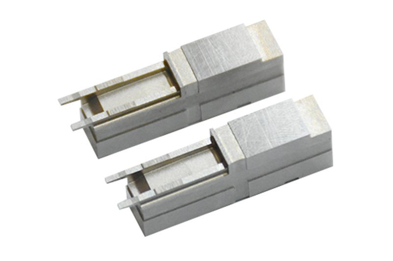
Representative Mold Cavity Insert Components





Related Product Catalogue and Quotation







Why Mold Cavity Inserts Need a Disciplined Process Route
SUUXIANG coordinates drawing review, DFM, machining and inspection around the dimensions and interfaces that govern mold performance.
Drawing-Led DFM Review
Review critical dimensions, datums, tool access, surface requirements and revision details before committing to a manufacturing route.
Planned CNC and EDM
Match CNC machining, wire EDM or sinker EDM to geometry, access constraints, corner conditions and electrode strategy.
Grinding Allowance Control
Plan grinding stock and heat-treatment sequence so final surfaces and critical fits can be evaluated against drawing requirements.
Fitting at Key Interfaces
Coordinate fitting considerations for mating features, locating surfaces and assembly interfaces where individual dimensions alone are insufficient.
Inspection Built Into Planning
Define inspection methods, critical features and reporting expectations early, keeping measured results aligned with the order and revision.
Traceable Project Coordination
Keep drawing updates, manufacturing decisions and delivery requirements visible throughout production for clearer communication between engineering and sourcing teams.
Drawing-Driven Mold and Precision Component Manufacturing
Configurable manufacturing routes for mold, connector and die-component requirements, planned around critical dimensions, material condition, inspection evidence and controlled revisions.

CNC Machining Services
Precision CNC machining services translate approved drawings and models into custom machined parts using planned milling, turning, EDM, grinding and inspection routes. Review focuses on critical dimensions, datums, material requirements, tool access and the documentation needed before production commitment.
Upload a Drawing
CNC Milling
Custom CNC milling services support prismatic mold components, plates, inserts, fixtures and custom machined features. Tool approach, internal radii, clamping strategy, datum references and remaining stock for EDM or grinding should be reviewed against the drawing.
Upload a Drawing
CNC Turning
Precision CNC turning services produce rotational features such as pins, bushings, sleeves, shafts and locating elements. Diameter tolerances, concentricity, runout, shoulder geometry, thread requirements and post-machining heat-treatment or grinding sequence require clear definition before routing.
Upload a Drawing
5-Axis Machining
5-axis CNC machining helps access angled, contoured and multi-face geometry with fewer setups where the part geometry justifies it. Drawing review evaluates tool reach, fixture access, datum transfer, surface requirements and whether EDM or finishing operations remain necessary.
Upload a Drawing
Swiss & Micro Machining
Swiss machining and micro machining support small-diameter, detailed components where handling, concentricity and feature access affect the process plan. Provide dimensions, material condition, quantities, critical features, surface needs and any mating-part context for an informed review.
Upload a Drawing
Wire & Sinker EDM
Wire EDM and sinker EDM services address hardened materials, narrow slots, sharp internal geometry, deep ribs and features inaccessible to conventional cutters. Electrode design, wire path, corner conditions, recast-layer considerations, flushing and finishing requirements should be agreed before machining.
Upload a Drawing
Precision Grinding
Precision surface and profile grinding brings controlled size, flatness, parallelism and profile condition to mold and die components. The process plan should define grinding stock, heat-treatment sequence, datum surfaces, wheel access, surface finish and inspection method.
Upload a Drawing
Mold Core & Cavity Inserts
Precision mold core inserts and mold cavity inserts are configured from the parting strategy, resin or molding application, cooling and venting needs, critical geometry and steel specification. CNC machining, EDM, grinding, fitting and inspection are selected according to the approved drawing package.
Upload a Drawing
Ejector & Ejection Components
Ejector pins, sleeves and ejection components are produced around fit, guidance, stroke and wear considerations. Specify diameters, clearance relationships, hardness or coating requirements, head geometry, surface condition and mating-component details so the ejection interface can be reviewed.
Upload a Drawing
Core Pins, Guide & Locating Components
Core pins, guide pins and locating components require controlled relationships to their mating bores and assembly datums. Drawing review should identify working diameters, guidance length, retention method, material condition, surface requirement and wear-sensitive interfaces.
Upload a Drawing
Slides, Lifters, Gates & Mold Accessories
Mold slides, lifters, gates and accessories are custom component families shaped by motion, shutoff geometry, resin flow and assembly constraints. Define travel, angles, contact surfaces, material and heat-treatment needs, lubrication provisions and critical fits for practical process planning.
Upload a Drawing
Connector Mold Components
Precision connector mold components support fine-pitch, repeatable tooling features where alignment, pin geometry, insert relationships and wear management matter. Share connector application context, mating geometry, material condition, critical dimensions, surface expectations and inspection priorities with the RFQ.
Upload a Drawing
Stamping Die Components
Precision stamping die components include punches, dies, plates, guides and locating elements produced to drawing-defined fit and wear requirements. Material grade, hardness sequence, edge condition, grinding allowance, clearance relationships and inspection criteria guide the manufacturing route.
Upload a Drawing
Injection, MIM, CIM & Overmolding Tooling
Injection, MIM, CIM and overmolding tooling components are evaluated within verified production scope for their geometry, material condition and application requirements. Drawing review addresses molding interface features, shrinkage responsibility, inserts, shutoffs, venting, surface needs and critical dimensions.
Upload a Drawing
Machining Materials
Injection mold components for MIM, CIM and overmolding are evaluated within verified production scope for their geometry, material condition and application requirements. Drawing review addresses molding-interface features, shrinkage responsibility, inserts, shutoffs, venting, surface needs and critical dimensions.
Upload a Drawing
Surface Finishes & Heat Treatment
Surface finishing and heat treatment must be planned with dimensional priorities, functional surfaces and subsequent grinding or EDM in mind. Specify finish type, hardness or treatment condition, masking needs, cosmetic expectations, corrosion requirements and how final dimensions will be verified.
Upload a Drawing
Quality, Metrology & Documentation
Precision inspection, metrology and quality documentation are planned around the order’s critical characteristics rather than generic claims. Identify CTQ dimensions, datum scheme, sampling or reporting needs, measurement method expectations, material records and revision-controlled documentation requirements.
Upload a Drawing
Prototyping & Low-Volume Production
Rapid prototyping and low-volume manufacturing support drawing-driven validation, bridge quantities and controlled component releases. Provide the latest drawing and model, material, quantity, delivery target, critical dimensions, surface needs and inspection requirements to establish a suitable route.
Upload a DrawingMold Cavity Inserts: Material Options

P20 Tool Steel
A practical choice for general-purpose cavity inserts where balanced machinability and polish response support straightforward production. Often considered for moderate-duty molding work, with hardness condition and post-machining requirements reviewed before release.

H13 Tool Steel
A robust hot-work steel option for inserts exposed to demanding thermal conditions or repeated cycling. Its process route should account for heat treatment, machining allowance, EDM strategy, and final grinding or polishing requirements.

S136 Stainless Steel
A corrosion-resistant steel option when molded-material conditions, storage environment, or surface-finish needs call for a cleaner cavity material. Polish target, heat-treatment condition, and machining sequence should be confirmed from the drawing.


Beryllium Copper Alloy
A high-conductivity insert material considered for localized cooling areas where thermal response matters. Its use requires careful review of structural support, feature geometry, mating interfaces, machining approach, and application-specific safety requirements.
Mold Cavity Inserts: Machining, EDM and Finishing


Wire EDM
Wire EDM supports through-features, sharp internal profiles and narrow contours where conventional cutting-tool access is limited. Wire-path planning considers datum transfer, corner conditions and finishing allowance for critical cavity insert geometry.

Sinker EDM
Sinker EDM forms deep cavities, fine internal features and geometry requiring shaped electrodes. Electrode strategy, burn allowance and subsequent finishing requirements should be aligned with surface, fit and critical-dimension expectations.

Precision Grinding
Precision grinding refines flatness, parallelism, size and datum-related surfaces after appropriate machining or heat-treatment stages. Grinding stock and inspection points are planned to protect mating conditions and dimensional control.

Component Fitting
Controlled fitting verifies how mold cavity inserts relate to adjacent cores, plates, slides or locating components. The work focuses on functional interfaces, assembly access and revision-sensitive conditions defined by the approved drawing.

Final Inspection
Inspection is planned around the order’s critical dimensions, datums, surface requirements and reporting needs. SUUXIANG matches documented results to the verified inspection plan, supporting traceability and clear revision communication.
Mold Cavity Inserts and Supporting Component Integration

Locating Elements
Locating pins, keys, and wear plates can establish repeatable insert position within the mold base. Provide datum references, fit requirements, material, and mating details so the interface can be reviewed before machining.

Guide Features
Guide pins, bushings, and alignment features support controlled mold-half movement and insert registration. Drawings should define critical diameters, surface requirements, clearance relationships, and any hardened or ground contact areas.

Gate Components
Gate inserts, sprue-related details, and runner-side components can be produced as drawing-driven work alongside cavity inserts. Gate geometry, polish expectations, material condition, and flow-sensitive surfaces require early review.

Slide Components
Slides, wedges, wear elements, and related locking features support side-action mold mechanisms. Include travel, interface datums, contact surfaces, lubrication provisions, and clearance requirements to guide machining and fitting planning.

Lifter Parts
Lifters and associated guide or bearing components can address undercuts during ejection. Accurate angle references, stroke requirements, mating geometry, and wear surfaces help determine suitable CNC, EDM, grinding, and inspection routes.

Ejection Parts
Ejector pins, sleeves, blades, and retention-related parts can be coordinated with mold cavity inserts when drawing requirements are clear. Identify fit zones, ejector travel, surface finish, material, and heat-treatment requirements for review.
About SUUXIANG Precision Manufacturing
SUUXIANG is the sole public-facing brand of Dongguan SuuXiang Precision Mold Co., Ltd., established in 2010 in Chang’an Town, Dongguan, Guangdong, China. XiaoCheng Huang is the founder and legal representative. We help international engineering and sourcing teams convert drawings and specifications into inspected precision mold components, connector-tooling parts and custom CNC-machined work.
Our drawing-driven workflow connects DFM review with CNC milling and turning, multi-axis machining, EDM, precision grinding, fitting, and inspection. For mold cavity inserts and related components, we review critical dimensions, datums, machining access, EDM needs, grinding allowance, material requirements, and inspection expectations before production commitments.
What distinguishes SUUXIANG is disciplined project coordination around the details that affect part acceptance: revision control, process sequence, traceable communication, and documentation aligned with the agreed inspection plan. Send your 2D drawing, 3D model when available, material, quantity, quality priorities, and delivery requirements for a focused manufacturing review.

Mold Cavity Inserts: Critical Capabilities in Detail
DFM and Datum Review
SUUXIANG reviews mold cavity inserts against the released drawing, model, mating features and application context before quotation. The discussion identifies critical dimensions, datum references, tolerance stack risks, tool access and process constraints that can affect the proposed manufacturing route.
- Confirm 2D drawing, 3D model, material, quantity and application requirements
- Identify critical-to-quality dimensions and measurement datums
- Review wall features, shutoffs, radii and cutter-access limitations
- Clarify heat treatment, surface and reporting requirements before production

EDM Strategy for Complex Geometry
Where milling access cannot achieve the required geometry, SUUXIANG plans wire EDM or sinker EDM as part of the insert process route. Electrode details, wire paths, corner conditions and finishing expectations should be aligned with the drawing and functional surfaces.
- Evaluate inaccessible details, sharp internal features and deep profiles
- Define electrode strategy for applicable sinker-EDM features
- Review wire-cut start locations, reliefs and path constraints
- Coordinate EDM finishing with subsequent grinding or fitting needs

Grinding Stock and Fitting
Grinding and fitting require intentional allowance planning rather than an afterthought at final assembly. SUUXIANG evaluates which surfaces require grinding stock, how heat treatment may affect the sequence, and how locating or mating interfaces should be protected through final fitting.
- Allocate grinding stock on surfaces requiring final correction
- Plan machining and heat-treatment sequence around critical interfaces
- Protect locating faces and reference surfaces during intermediate operations
- Review fitting relationships with adjacent cores, slides or mold plates

Inspection and Revision Control
Inspection planning for mold cavity inserts should follow the drawing’s critical dimensions and agreed reporting requirements. SUUXIANG keeps revision information visible through project coordination, aligns inspection methods to the verified plan, and matches final documentation to the released order requirements.
- Establish inspection priorities from critical dimensions and datums
- Agree required reports, measurement methods and acceptance criteria
- Maintain drawing revision visibility throughout project coordination
- Confirm final documentation against the verified inspection plan

Why Choose SUUXIANG for Mold Cavity Inserts
A drawing-led workflow that makes critical requirements, process decisions and inspection expectations visible before production.
← Swipe left or right to view →
Mold Cavity Inserts: From Drawing Review to Shipment
A disciplined workflow keeps critical dimensions, process decisions, inspection requirements and revision information visible before production commitments are made.
Review Drawings and Requirements
We review 2D drawings, available 3D models, material, quantity, application context, critical dimensions, surface requirements, inspection needs and target delivery date.
Plan the Process Route
DFM discussion confirms datum strategy, machining access, tolerance stack, heat-treatment sequence, EDM requirements, grinding allowance and a practical inspection plan before quotation.
Machine Critical Geometry
CNC milling, turning, multi-axis machining, wire EDM and sinker EDM are selected according to geometry, tool access, electrode strategy and specified features.
Grind, Fit and Finish
Grinding stock, fitting interfaces and surface requirements are managed in sequence so mating relationships and critical mold cavity insert details remain reviewable.
Inspect Against the Plan
Finished parts are inspected against the agreed drawing revision and inspection method, with documentation matched to the order and verified quality requirements.
Pack and Coordinate Delivery
Parts are protected for shipment while revision status, required documentation and delivery coordination remain visible to support receiving inspection and project scheduling.
Work With SUUXIANG on Mold Cavity Inserts
Move from drawing review to controlled production with clear technical inputs, documented decisions and revision visibility.
Submit Drawings and Requirements
Provide 2D drawings, 3D models when available, material, quantity, critical dimensions, surface requirements, inspection needs and target delivery date.
Review DFM and Quotation
Confirm datum strategy, machining access, EDM or grinding requirements, heat-treatment sequence, tolerance priorities, inspection approach and any production assumptions before commitment.
Approve Samples When Needed
For development or higher-risk mold cavity inserts, review agreed sample, dimensional evidence and revision feedback before releasing the next production stage.
Coordinate Production and Documentation
SUUXIANG coordinates the approved CNC, EDM, grinding, fitting and inspection route, then supplies documentation aligned with the order and verified inspection plan.
Mold Cavity Inserts: Certification and Documentation Review
Customer Case Study Publication Policy
Approved customer case study pending: project scope, process route, inspection evidence, and measurable outcome will be published only with customer authorization.
Approved customer case study pending: this slot is reserved for a verified drawing-based mold component project and its documented sourcing or quality outcome.
Approved customer case study pending: SUUXIANG will publish only customer-approved quotations and results supported by project records.
Mold Cavity Inserts FAQ
Practical guidance for specifying, reviewing and sourcing drawing-driven cavity insert work.
What information should I send for a mold cavity inserts quote?
Is there a minimum order quantity for mold cavity inserts?
Can you make samples before production of mold cavity inserts?
How do you select material and heat treatment for cavity inserts?
What is the lead time for custom mold cavity inserts?
What inspection documents can accompany mold cavity inserts?
Can SUUXIANG ship mold cavity inserts internationally?
How are drawing revisions and intellectual property handled?
Complete Buyer’s Guide to mold cavity inserts
Use this decision framework to specify mold cavity inserts, compare supplier engineering and quality controls, manage lifecycle cost, and avoid drawing, material, tolerance, and validation mistakes that delay tooling programs.
1. What Are Mold Cavity Inserts?
Two mold halves create the functional divide: the fixed-side cavity insert forms the molded part’s external geometry, cosmetic surface and localized detail, while the movable-side core insert forms internal features and normally carries the part for ejection. Both are precision tooling elements seated and located within a larger mold structure.
Cavity inserts are often replaceable because wear, damage, polishing changes or an engineering revision may be limited to one feature rather than the entire tool. Modular construction can also make deep details more accessible for CNC machining, EDM, grinding, fitting and inspection.
Monolithic machining is usually sensible when geometry is simple, access is open and future localized replacement is unlikely. An insert is preferable when a feature needs a separate process route, controlled heat-treatment sequence, service access or steel-safe revision margin; the drawing should define datums, retention, parting interfaces and critical dimensions before release.
2. Evolution of Mold Insert Tooling
In 1952, numerical-control milling demonstrated that complex mold geometry could be reproduced from programmed coordinates rather than solely by manual layout. CNC later made revision-controlled cavity blocks and mold cavity inserts more practical to source, provided the supplier could relate the model, drawing datums and inspection plan.
By the 1960s, EDM had become an essential complement to milling for deep ribs, sharp internal details and forms with limited cutter access. Its use with hardened tool steels shifted sourcing attention toward heat-treatment sequence, machining allowance, electrode strategy, wire path and the condition of EDM-affected surfaces before polishing or service.
Three modular-tooling benefits now drive lifecycle value: localized engineering changes, replacement of worn features and repair without remaking an entire cavity block. Buyers should therefore specify insert retention and datum interfaces, interchangeability requirements, hardness condition, critical dimensions and the inspection evidence required after repair or revision.
3. Types of Mold Cavity Inserts
Two mold halves create distinct access and retention constraints. Classifying inserts before release helps the team match machining, maintenance access, and likely engineering-change exposure.
Cavity-Side And Core-Side
Cavity-side inserts form exterior surfaces on the fixed half and commonly need polished, vented, or textured faces.
Core-side inserts form internal features on the moving half; ejection clearance, undercuts, and tool reach drive their geometry.
Replaceable And Integral Blocks
Replaceable inserts use screws, keys, and support faces to localize repair or revision work.
Integral blocks maximize continuity and rigidity, but a damaged detail can require reworking the complete block; use them for simple, stable geometry.
Mounting And Moving Inserts
Bottom-mounted inserts suit deep pockets because removal occurs from the back after separating the mold half.
Side-mounted, shutoff, and slide-related inserts need positive retention against molding force; wire EDM, sinker EDM, and fitting often control mating faces.
Modular Multi-Cavity Sections
Multi-cavity tools can use repeatable cavity modules so one worn or changed position is serviced independently.
Common datums, interchangeability tolerances, and identification marks are essential when modules must run consistently across positions.
4. Materials for Mold Cavity Inserts
Material selection starts with resin, service environment, and expected production life. For mold cavity inserts, grade choice must also fit finishing, repair, and inspection requirements.
| Family | Typical Selection Driver | Key Control |
|---|---|---|
| Pre-hardened steel | Moderate runs; easier machining | Verify delivered hardness |
| Through-hardened steel | Wear resistance after heat treatment | Allow finish grinding |
| Hot-work steel | Thermal cycling or hot resins | Control treatment sequence |
| Corrosion-resistant steel | Corrosive resins or humidity | Confirm chemistry and hardness |
| High-polish steel | Optical or cosmetic surfaces | Protect polish process |
| Aluminum | Prototype, low-volume tooling | Plan for limited wear life |
Match Resin And Environment
Glass-filled or mineral-filled resins increase wear risk at gates, corners, and sliding interfaces. PVC, flame-retarded compounds, and humid storage can prioritize corrosion resistance.
Expected cycles should be stated as a project input, not inferred from part size. Thermal loading and cooling layout can change the preferred steel family.
Plan Finishing And Repairs
Mirror-polished cosmetic surfaces need steel cleanliness and a finishing route compatible with the specified polish. Textured surfaces require adequate hardness and a controlled pre-texture condition.
Weld repair is not interchangeable across steel families. Define repair zones, subsequent stress relief, and final re-machining or polishing before release.
Control Material Evidence
Heat treatment changes distortion risk, machining allowance, and final grinding strategy. Confirm sequence before CNC, EDM, and finishing are scheduled.
Supplier traceability should connect each blank to its material certificate, stated condition, and revision-controlled order. SUUXIANG can review this evidence against the drawing and inspection plan.
5. Mold Cavity Inserts: Surface Options
Two surface roles—functional release and cosmetic replication—should be specified separately on mold cavity inserts. Finish selection affects molded appearance, wear, cleaning effort, lead time, and post-process measurement.
| Surface Option | Primary Effect | Drawing Definition |
|---|---|---|
| CNC machined | Economical functional finish | Ra, direction, boundaries |
| Polished | Gloss and release | Grade, cosmetic zone |
| EDM or texture | Appearance and release control | Texture reference, area, draft |
| Coating | Wear or corrosion response | Treatment, excluded surfaces |
Machined And Polished Finishes
Ra values, polish grade, direction, and finish boundaries should reference drawing datums and cosmetic zones. A finer polish can improve gloss and release, but adds handwork and may soften sharp edges.
EDM And Applied Textures
EDM texture, chemical etch, and laser texture require an approved reference panel or texture code before steel is cut. Specify textured area, draft direction, masking limits, and permitted post-texture polishing.
Coatings And Protection
Coating or corrosion-protection callouts should name the treatment, substrate condition, excluded fit surfaces, and thickness range where relevant. Confirm post-treatment measurement requirements and the accepted inspection method.
6. Critical Mold Cavity Insert Quality Elements
Quality begins at the drawing datums, not at final polishing. Mold cavity inserts require matched controls for geometry, thermal behavior, wear surfaces, and verification.
Datums, Fits, And Shutoffs
Primary, secondary, and tertiary datums should locate every critical feature and insert seat. Uncontrolled seat clearance or damaged shutoffs can permit flash, shift cavity geometry, and complicate replacement.
DFM should identify locating faces, fit direction, shutoff land, steel-safe surfaces, and repair access. It should also flag thin steel and tool-access limits before machining.
Draft, Venting, And Cooling
Draft must suit the resin, texture, depth, and intended ejection direction. Insufficient draft raises release force, scuffing, and poor ejection risk.
Vent locations and cooling proximity need review against flow end, weld areas, local heat load, and remaining steel section. Poor venting can burn or short-fill parts; uneven cooling drives cycle-to-cycle dimensional variation.
Hardness, Finish, And Inspection
Hardness, surface finish, and heat-treatment sequence must be specified by function rather than assumed. A finish that supports appearance may not protect a high-wear shutoff, and post-treatment distortion may consume grinding allowance.
Inspection records should state revision, datum setup, measured critical dimensions, method, instrument status, acceptance result, and any deviation. Require DFM and inspection plans to connect each critical feature to a measurement method.
7. How to Choose an Insert Manufacturer
A drawing-based supplier should turn the RFQ into a documented manufacturing plan, not merely a price. For mold cavity inserts, evaluate how questions, process choices, and inspection evidence are handled before release.
Test DFM Response
Before quotation, ask for a review of datums, critical dimensions, tool access, EDM electrodes, wire paths, grinding stock, and heat-treatment sequence.
For ambiguous drawings, require written assumptions and a hold point; never let an unstated interpretation become the released revision.
Verify Process And Evidence
For each critical feature, ask which CNC, EDM, grinding, and metrology method will control it. Material identification, heat-treatment records where specified, and inspection reports must match the purchase order.
For mating features, ask how the supplier understands mold function, fitting interfaces, venting, polish requirements, and steel-safe changes.
Control Handoffs And Revisions
Before shipment, define revision ownership, report format, deviation approval, delivery status, rust prevention, and protective packaging. Procurement should confirm that communication remains traceable from RFQ through inspection.
For critical dimensions, require the drawing ballooning method, measurement datum, instrument, and acceptance decision to be agreed before machining begins.
8. Common Mold Cavity Insert Buying Mistakes
Mold cavity insert failures often begin before machining, when a drawing lacks the information needed to control function. Resolve these issues during drawing release, not after steel is cut.
Datum And Mating Definition
Functional datums—not isolated dimensions—control how an insert locates against its pocket, shutoff, and mating core.
Before release, define contact faces, locating features, assembly clearances, and the inspection datum scheme; otherwise, parts may inspect correctly yet misalign in the mold.
Material And Finish Requirements
Material grade, hardness condition, and heat-treatment sequence determine machining allowance and final stability.
Surface finish also affects release, sealing, wear, and texture transfer; specify the functional area, finish requirement, and measurement method rather than calling it cosmetic.
Molding Behavior Assumptions
Shrinkage and draft alter the steel geometry required to produce the intended molded part.
Before release, provide resin, shrinkage basis, draft direction, gate context, and critical molded dimensions; omissions can trigger trial rework or an unusable cavity.
DFM And Quote Comparison
DFM review exposes tool access, EDM electrode strategy, wire paths, grinding stock, and tolerance conflicts before manufacture.
Compare quotations by process route, inspection plan, revision control, and delivery assumptions—not unit price alone—because a lower quote may exclude necessary operations.
9. From Drawing Release to Mold Trials
A controlled insert launch starts with released 2D drawings, current 3D models, and an explicit list of critical-to-function features. The manufacturing route should remain traceable from drawing review through trial feedback.
Release The Manufacturing Package
1 package should identify revision level, datums, material, heat treatment, finish, quantity, and inspection requirements.
2 data formats—the dimensioned drawing and native or neutral 3D model—should agree before machining approval.
- Mark CTQ dimensions and mating interfaces
- State cosmetic and texture surfaces
- Provide application and resin context
Review Before Cutting Steel
1 DFM review should confirm tool access, EDM electrodes or wire paths, grinding stock, datum transfer, and inspection method.
2 approvals should record any accepted deviation, steel-safe allowance, and responsibility for final dimensional adjustment.
- Confirm material and finish route
- Freeze the approved revision
- Define pre-shipment inspection evidence
Close The Trial Feedback Loop
T0 sampling should compare molded-part dimensions, fill, venting, ejection, and appearance against the agreed acceptance criteria.
1 engineering-change record should link trial observations to insert revision, steel removal or replacement, reinspection, and the next T1 trial.
- Retain sample and measurement records
- Prevent unapproved drawing changes
- Update revision status before shipment
10. Mold Cavity Insert Pricing and Cost Drivers
1 drawing revision can change quoted cost more than a nominal quantity increase when it forces CAM rework, new electrodes, or a revised inspection plan. SUUXIANG should quote from the released 2D drawing, model, material, application, and identified critical dimensions.
2 cost decisions deserve separate review: manufacturing the insert and protecting its lifecycle value. Larger stock, hardened or corrosion-resistant material, tighter tolerances, EDM detail, polishing, heat treatment, coating, and reporting each add time, risk, or outside-process coordination.
| Complexity tier | Setup effort | Machining and inspection | Lead-time influence | Lifecycle tradeoff |
|---|---|---|---|---|
| Simple prismatic CNC insert | Low | Short milling; standard dimensional checks | Low | Lowest initial cost; limited change isolation |
| Precision ground insert | Medium | Grinding stock, datum control, added measurement | Moderate | Higher repeatability for critical fits |
| EDM-detail cavity insert | High | Electrodes or wire paths; EDM cleanup; feature inspection | High | Enables inaccessible geometry; repairable locally |
| Hardened, polished, or coated insert | High | Sequenced machining, treatment, finishing, verification | High | Higher initial cost; may reduce wear or corrosion risk |
| Revision-prone modular insert | Medium to high | Interface control and revision-specific inspection | Moderate | Can avoid replacing a larger cavity block |
Upload Your Drawing for a Mold Cavity Insert Quote
Share 2D or 3D files, material, quantity, critical dimensions, inspection needs, and target delivery date for SUUXIANG’s engineering review.