
Mold Support Pillars Built to Your Drawing
Submit your mold support pillars drawing for DFM review, process planning, and inspection-focused production.
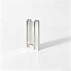
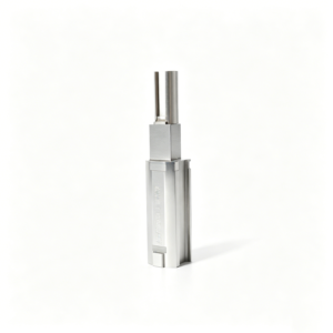
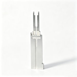
Representative Components for Mold Support Pillar Development





Related Configurable Components and RFQ Support






Why Source Mold Support Pillars Through SUUXIANG
A drawing-driven workflow for support components where fit, load paths, machining access, and inspection requirements need clear technical coordination.
Drawing Review First
We review drawings, models, material requirements, quantities, and application context before discussing manufacturability, critical dimensions, or production commitments.
Process Route Planning
CNC machining, EDM, grinding, fitting, and inspection are planned around geometry, tool access, surface requirements, and heat-treatment sequence.
Critical Dimensions Focus
Datum strategy, tolerance stack, mounting features, and mating interfaces receive focused review so mold support pillars fit their intended assembly.
Coordinated Precision Processes
Appropriate CNC, wire EDM, sinker EDM, and grinding operations are coordinated to address geometry, access constraints, and finishing needs.
Inspection Planning
Inspection methods and reporting expectations are aligned to the order, helping teams define evidence for critical features before production begins.
Revision Visibility
Drawing revisions, agreed requirements, and delivery information remain visible through project coordination, supporting traceable communication across engineering and sourcing teams.
Mold Support Pillars and Tooling Component Families
Drawing-driven component families for mold, connector and die programs, planned around critical dimensions, process access and inspection requirements.

CNC Machining Services
Precision CNC machining services for drawing-based mold components, support pillars and custom tooling parts. Process planning considers material, datums, critical dimensions, machining access, heat-treatment sequence and inspection requirements before production commitments are made.
Upload a Drawing
CNC Milling
Custom CNC milling services for prismatic components, plates, inserts and support structures. Tool access, wall geometry, clamping strategy and required machining allowances are reviewed against the drawing and 3D model before the machining route is confirmed.
Upload a Drawing
CNC Turning
Precision CNC turning services for shafts, sleeves, pins, bushings and other rotational tooling components. Diameters, concentricity, threads, datum relationships and finishing allowances should be defined in the RFQ and verified through the inspection plan.
Upload a Drawing
5-Axis Machining
5-axis CNC machining supports complex mold inserts, shaped surfaces and multi-face components where repositioning can introduce risk. The process route is evaluated around tool reach, fixture access, surface requirements and critical dimensional relationships.
Upload a Drawing
Swiss & Micro Machining
Swiss machining and micro machining support small, slender and detail-intensive parts such as fine pins, miniature sleeves and connector-tooling features. Drawing review should identify diameter-to-length ratios, handling risks, material condition and inspection methods.
Upload a Drawing
Wire & Sinker EDM
Wire EDM and sinker EDM services address profiles, internal corners, hardened materials and features with limited conventional tool access. Electrode strategy, wire path, EDM allowances, surface requirements and downstream fitting or polishing needs are reviewed per part.
Upload a Drawing
Precision Grinding
Precision surface and profile grinding supports flatness, parallelism, profile control and final size adjustment on tooling components. Grinding stock, heat-treatment distortion risk, datum sequence and inspection method should be established before finishing.
Upload a Drawing
Mold Core & Cavity Inserts
Precision mold core and cavity inserts are configurable drawing-based components for injection tooling. Their manufacture is planned around cavity geometry, material, heat treatment, cooling or venting features, EDM requirements, mating interfaces and critical inspection points.
Upload a Drawing
Ejector & Ejection Components
Ejector pins, sleeves and ejection components are produced to drawing-defined dimensions and interface conditions. Fit with plates, cores and mating parts requires clear diameter tolerances, surface requirements, hardness specifications and revision-controlled documentation.
Upload a Drawing
Core Pins, Guide & Locating Components
Core pins, guide pins and locating components support repeatable alignment, molding geometry and controlled assembly. RFQs should identify datum surfaces, fit class, material and heat treatment, wear expectations, mating components and dimensions requiring inspection.
Upload a Drawing
Slides, Lifters, Gates & Mold Accessories
Mold slides, lifters, gates and accessories are configurable tooling elements requiring coordinated interface review. Travel geometry, bearing surfaces, clearances, gate design intent, material condition and fitting requirements should be clarified before machining begins.
Upload a Drawing
Connector Mold Components
Precision connector mold components support tooling for connector-product features where pitch, alignment, pin geometry and repeatability are critical. The drawing review addresses micro features, mating relationships, material, EDM or grinding needs and inspection priorities.
Upload a Drawing
Stamping Die Components
Precision stamping die components are manufactured from customer drawings for forming, cutting and guiding functions. Process planning considers tool steel condition, heat-treatment sequence, clearance relationships, grinding stock, wear surfaces and assembly-critical dimensions.
Upload a Drawing
Injection, MIM, CIM & Overmolding Tooling
Injection, MIM, CIM and overmolding tooling components are evaluated within verified production scope. Manufacturing discussions address material behavior, feature geometry, insert interfaces, molding-related surfaces, tooling loads and the machining, EDM, grinding and inspection route.
Upload a Drawing
Machining Materials
CNC machining materials are selected from the drawing and application requirements rather than assumed from a catalog. Material grade, supply condition, hardness, corrosion needs, heat treatment and traceability requirements should be stated before quotation.
Upload a Drawing
Surface Finishes & Heat Treatment
Surface finishing and heat treatment are coordinated with dimensional requirements and the selected process route. Specify target condition, surface priorities, masking or post-process needs, distortion concerns and any documentation required to verify the ordered treatment.
Upload a Drawing
Quality, Metrology & Documentation
Precision inspection, metrology and quality documentation are planned around drawing-defined critical dimensions and agreed acceptance criteria. Customers should identify reporting needs, datum references, measurement methods, material records and revision-control expectations with the RFQ.
Upload a Drawing
Prototyping & Low-Volume Production
Rapid prototyping and low-volume manufacturing support drawing-driven evaluation, tooling development and controlled production needs. Quantities, material condition, critical dimensions, delivery target, inspection scope and expected revision cadence determine the appropriate process plan.
Upload a DrawingMaterial Options for Mold Support Pillars

P20 Tool Steel
A practical pre-hardened steel option for support pillars and related mold plates requiring balanced machinability and strength. Suitability depends on section size, working load, mating surfaces, and the specified hardness condition.

H13 Tool Steel
A hot-work tool steel considered when thermal cycling, elevated-temperature service, or higher toughness requirements influence the design. Heat-treatment sequence, grinding allowance, and final inspection criteria require project-specific review.

S50C Carbon Steel
A medium-carbon steel option for drawing-defined support and structural tooling components where the required strength, finish, and heat-treatment condition are clearly specified. Machining access and mating-face requirements guide process planning.

Alloy Tool Steel
Alloy steel grades can be selected for projects needing a defined balance of hardness, toughness, wear resistance, or through-hardening response. Material designation and heat-treatment documentation should be established before quotation.

Stainless Tool Steel
Stainless steel may fit support-pillar assemblies exposed to moisture or corrosion-sensitive environments. Grade selection must consider corrosion resistance, attainable hardness, machining behavior, and the component’s actual contact or load conditions.
Mold Support Pillars: Machining and Finishing Processes

CNC Milling
CNC milling forms pillar bodies, mounting faces, pockets, and clearance features from drawing-defined stock. Tool access, datum selection, and machining allowance are reviewed to support stable geometry before finishing operations.

CNC Turning
CNC turning produces concentric diameters, shoulders, end faces, and threaded features for mold support pillars. The route is selected when rotational geometry and controlled relationships to mounting surfaces are critical.

Wire EDM
Wire EDM cuts precise profiles, slots, and clearance shapes where conventional tools cannot reach cleanly. Wire-path planning considers datum references, corner conditions, and any downstream fitting or inspection requirement.

Sinker EDM
Sinker EDM creates detailed cavities or nonstandard feature geometry using an electrode strategy matched to the drawing. Electrode access, finish expectations, and subsequent polishing or fitting needs are reviewed in advance.


Fitting and Inspection
Fitting and inspection confirm that mold support pillars align with the specified assembly context and approved quality plan. Measurement methods, critical dimensions, revision status, and required documentation remain visible through delivery.
Mold Support Pillars: Mounting Features and Component Details

Threaded Ends
Specify thread size, engagement length, tolerance class, relief details, and mating fastener requirements for mold support pillars that mount directly into plates or accept extension components.

Clearance Holes
Clearance-hole diameter, counterbore geometry, screw access, and positional relationship to the mounting interface should be defined where the pillar must accommodate fasteners or assembly movement.

Locating Details
Dowel holes, pilot diameters, shoulders, and other locating details help establish repeatable positioning. Identify the governing datum and mating-component relationship so the interface can be manufactured and inspected correctly.

Ground Support Faces
Ground end faces can support controlled contact against mold plates. State flatness, parallelism, surface-finish priorities, and the datum scheme when face contact affects load transfer or assembly alignment.

Plate Interface Requirements
Provide plate thickness, pocket geometry, nearby ejector clearance, assembly stack-up, and critical dimensions. This context helps review tool access, machining sequence, and inspection needs before a quotation is finalized.
About SUUXIANG
SUUXIANG is the sole public-facing brand of Dongguan SuuXiang Precision Mold Co., Ltd., established in 2010 and based at 2nd Floor, Sanhe Industrial Park, Chang’an Town, Dongguan, Guangdong, China. XiaoCheng Huang is the founder and legal representative. We help global engineering and sourcing teams translate drawings into inspected mold support pillars, precision mold components, connector tooling, die components, and custom CNC-machined parts.
Our workflow begins with drawing review, DFM discussion, and identification of critical dimensions, datum strategy, material, heat treatment, surface requirements, and inspection needs. CNC machining, EDM, grinding, fitting, and quality control are planned around the part rather than treated as a generic quotation.
What differentiates SUUXIANG is disciplined coordination from revision-controlled input through inspection documentation and delivery planning. For support pillar projects, we review installation context, interfaces, clearance needs, and dimensional priorities before production commitments, helping buyers align the process route and evidence package with their application.

Engineering Capability for Mold Support Pillars
DFM and Datum Review
SUUXIANG reviews the drawing before quotation to clarify functional datums, critical heights, mounting interfaces, and clearance around ejector-system features. This gives the project team a documented basis for discussing manufacturability, inspection priorities, and revision-controlled production requirements.
- Confirm datum references and critical-to-quality dimensions
- Review mounting holes, threads, and interface geometry
- Identify clearance risks with adjacent mold actions
- Align drawing revisions before production planning

CNC, EDM, and Grinding Route
Each support-pillar design is evaluated for the process sequence its geometry requires. CNC machining, EDM, precision grinding, and fitting are considered together so tool access, feature definition, surface requirements, and practical machining allowances are addressed before the route is released.
- Select machining routes from drawing geometry
- Review wire paths and electrode requirements
- Plan grinding stock around finished faces
- Consider heat-treatment sequence where specified

Controlled Height and Fit
For mold support pillars, functional height and mating contact conditions deserve separate attention from noncritical external features. SUUXIANG uses the supplied drawing to define finishing references and evaluate parallel contact surfaces, creating a documented discussion of assembly fit and intended mold support.
- Prioritize functional height from the specified datum
- Review contact faces and parallelism requirements
- Separate critical fits from general dimensions
- Flag mating-component information needed for review

Inspection Plan Before Release
Inspection preparation begins with the drawing, not at final packing. SUUXIANG aligns measurement methods and reporting expectations with identified critical dimensions, surface priorities, and customer documentation requirements, helping procurement and quality teams request the evidence relevant to the ordered component.
- Define inspection points from critical drawing callouts
- Match reporting needs to the agreed inspection plan
- Maintain traceable revision and order information
- Request material, quantity, and delivery requirements early

Mold Support Pillars: Drawing Review vs. Generic Quotation
Compare the project evidence needed before production commitments are made.
← Swipe left or right to view →
From Mold Support Pillars Drawing Review to Delivery
Each route is planned against the drawing, critical dimensions, inspection needs and delivery requirements confirmed for the project.
Review RFQ Package
We review drawings, models, material, quantity, application context, target date and reporting requirements, then identify information needed before a responsible quotation.
Confirm DFM Priorities
The team discusses datums, critical dimensions, tolerance stack, mounting features, machining access, heat-treatment sequence and inspection approach before production commitments are made.
Plan Process Route
A project-specific route is defined across CNC machining, turning, EDM, grinding and fitting, including allowances and workholding considerations where applicable.
Machine Critical Features
Mold support pillars are machined to the approved drawing revision, with process choices aligned to geometry, surface requirements and required functional interfaces.
Inspect and Document
Completed parts are checked against the agreed inspection plan, with measurement records and order documentation prepared according to verified project requirements.
Coordinate Packing and Shipment
After release, packing and shipment coordination follow the confirmed order details, while revision status and delivery information remain visible to the customer.
How to Work With SUUXIANG on Mold Support Pillars
Provide complete engineering inputs early so DFM review, process planning, inspection expectations, and delivery coordination can be aligned before production commitments.
Submit Your Drawing Package
Send the 2D drawing and available 3D model, identifying mold support pillar interfaces, assembly context, revision level, and any mating-component constraints.
Define Technical Requirements
Specify material, heat treatment, quantity, critical dimensions, datums, surface requirements, delivery target, and any inspection reports or quality documentation required.
Review DFM and Process Route
Align with SUUXIANG on machinability, tool access, machining allowance, EDM or grinding needs, measurement methods, and risks affecting the requested design.
Confirm Quote and Samples
Review the proposed manufacturing scope, inspection plan, revision controls, commercial terms, and sampling requirements before releasing mold support pillars for coordinated production.
Coordinate Production and Inspection
Follow agreed revision and delivery information while SUUXIANG coordinates machining, fitting where required, final inspection, and documentation matched to the verified order plan.
Certifications and Quality Documentation for Mold Support Pillars
Mold Support Pillars: Verified Customer Feedback
Approved customer testimonial pending verification: document the drawing revision, critical support-pillar dimensions, inspection result, and measurable delivery or quality outcome before publication.
Approved customer testimonial pending verification: include the component quantity, material and heat-treatment requirements, dimensional priorities, and the inspected outcome supported by the order record.
Approved customer testimonial pending verification: record the DFM issue identified, agreed revision control, inspection documentation, and a measurable result such as reduced rework or on-time delivery.
Mold Support Pillars FAQ for Drawing-Based RFQs
Clarify dimensions, materials, quality evidence, delivery requirements, and confidential drawing handling before requesting a quotation.
Can SUUXIANG make custom mold support pillars from my drawing?
What dimensions should I provide for mold support pillars?
What material and heat-treatment information is needed for mold support pillars?
How tight can the tolerances be on a custom support pillar?
Can you provide inspection reports for mold support pillars?
How is lead time confirmed for custom mold support pillars?
Can SUUXIANG ship mold support pillars internationally?
How are confidential drawings and IP-sensitive designs handled?
The Complete Buyer’s Guide to mold support pillars
A practical decision framework for specifying mold support pillars, evaluating capable suppliers, validating quality, and avoiding dimensional, material, installation, and sourcing mistakes that can compromise mold rigidity and production reliability.
1. What Are mold support pillars?
DGMF defines support pillars as components mounted between the backup plate and rear clamping plate; parallel to spacer blocks, they reinforce the mold’s core-side structure. Their height normally matches the spacer-block height, while the ejector plate requires clearance so it can travel around them without collision. Source: https://dgmfmoldclamps.com/support-pillars-injection-mold-components
HASCO notes that support pillars bridge large gaps between mold risers and increase rigidity when cavity filling loads could deflect the tool. That stiffness helps preserve parting-surface stability, reducing the risk of ‘mold breathing’ under injection pressure. Source: https://www.moldmakingtechnology.com/products/support-pillar-with-clearance-hold-and-thread-maximizes-mold-design-freedom
A designer should assess pillars when projected cavity area, injection pressure, plate span, or core-side mass makes unsupported plates vulnerable to bending. Locate them within usable ejector-space clearance, then check interference with ejector pins, lifters, slides, return hardware, cooling, and other moving actions before freezing the layout.
2. How Mold Support Evolved
Two solid, full-contact supports were once commonly specified simply as pillars sized to fit the available ejector-box space. As mold bases became larger and projected cavity areas increased, buyers needed defined support locations and ground end faces so load transfer could be controlled rather than left to nominal stock length.
25–100 mm diameters and 36–196 mm lengths were published for Hasco Z571 support pillars, illustrating how standardized size series made modular mold-base selection and replacement more practical. The same product used a clearance hole and thread for alternative fixing methods when high injection pressures must be absorbed; source: https://www.moldmakingtechnology.com/products/support-pillar-with-clearance-hold-and-thread-maximizes-mold-design-freedom.
Two tapped ends can also permit pillars to be joined for a longer assembly, while drilled, counterbored, doweled, and threaded patterns give designers distinct fastening and locating choices. In an RFQ, specify the mounting pattern, finished height, ground-face requirement, clearance-envelope conflicts, and whether the pillar is a structural support or a locating feature; do not assume one design serves both functions.
3. Types of mold support pillars
Six practical mold support pillar configurations differ mainly in fastening and clearance management. Select the form only after the ejector layout, lifter sweep, moving-plate travel, and available plate thickness are checked from the assembly drawing.
| Configuration | Mounting Method | Benefit And Typical Use | Interference Check |
|---|---|---|---|
| Solid cylindrical | Trapped or face-mounted | Simple plate support; standard layouts | Confirm ejector-plate opening |
| Tapped | End threads | Removable service access | Protect thread from moving hardware |
| Threaded extension | Coupled tapped ends | Longer assembled reach | Check joint and lifter envelope |
| Doweled | Fastener plus dowel | Repeatable location | Reserve pin and ejector space |
| Drilled and counterbored | Recessed screw head | Flush mounting | Counterbore must clear travel |
| Clearance-hole | Through-hole with thread option | Flexible fixing location | Verify screw and plate clearance |
Catalog Or Custom
Standard catalog pillars suit nominal diameters, lengths, and familiar fastening schemes. Drawing-based parts are appropriate when a nonstandard shoulder, datum feature, relief, coating, or inspection requirement changes the interface.
Interference Review
One assembly-section review should show pillar envelopes against ejector pins, lifters, return hardware, and moving plates. Specify clearance holes, counterbores, or reduced sections from the actual travel path rather than adding relief after machining.
4. Materials for mold support pillars
Four material families cover most mold support pillar decisions: carbon steel, pre-hardened mold steel, alloy/tool steel, and corrosion-resistant alternatives. Final selection and heat treatment must follow the tool drawing and calculated load case.
| Material Family | Selection Focus | Manufacturing Consideration |
|---|---|---|
| Carbon steel | Moderate loading; controlled environment | Efficient machining and grinding route |
| Pre-hardened mold steel | Stable hardness without post-machining distortion | Confirm supplied condition and finish stock |
| Alloy/tool steel | Higher load, wear, or thermal demand | Define heat treatment and toughness requirement |
| Corrosion-resistant alternative | Corrosive processing or storage exposure | Verify grade, hardness, and grindability |
Match Material To Load
Compressive loading, unsupported length, and contact area determine whether a basic structural steel is adequate or higher hardness and toughness are needed.
Thermal exposure and cyclic loading can change the preferred balance between strength, stability, and crack resistance.
Plan The Manufacturing Route
Machinability affects turning and drilling time; grindability affects how reliably final height, parallelism, and bearing faces can be finished.
Heat treatment should be sequenced with machining allowance and final grinding stock shown on the drawing.
Control Corrosion And Records
Corrosive resin environments, humidity, and storage conditions may justify corrosion-resistant material or protective measures.
Material certificates, heat-treatment records, and inspection results should remain linked to the part revision and order requirements.
5. Custom mold support pillars
Drawing-defined mold support pillars should be engineered around the mold’s actual rear-half envelope, not selected by nominal diameter alone. SUUXIANG reviews functional dimensions, interfaces, and inspection requirements before confirming a feasible process route.
Define Functional Geometry
Three primary dimensions—diameter, finished length, and end-face perpendicularity—should reference stated datums. Specify whether both ends require grinding and identify any controlled parallelism or runout.
Threads, through-holes, counterbores, dowel bores, and relief features need sizes, depths, class, and positional tolerances. Include coating, corrosion protection, or part-marking requirements where applicable.
Check Mold Envelope
Spacer-block height establishes the installed pillar length; tolerance must preserve intended plate support without preloading or clearance. Plate thicknesses, mounting access, and fastener-head clearance also constrain the design.
Adjacent ejector plates, pins, return mechanisms, and lifters require documented keep-out zones. Send a rear-half assembly section when a special clearance, partial support location, or nonstandard profile is needed.
RFQ Drawing Checklist
One RFQ package should identify the revision-controlled 2D drawing and, when available, the 3D model. Define material, heat treatment, quantity, critical dimensions, surface requirements, and requested inspection evidence.
Two installation references—the spacer-block height and plate layout—help verify fit before machining. State mating parts, installation method, delivery target, and any marking or traceability requirement.
- Finished diameter and installed length
- Datum scheme and critical tolerances
- Thread, hole, counterbore, and dowel details
- Ejector-area keep-out dimensions
- Inspection report and revision requirements
6. Construction and Inspection Essentials
A support pillar performs only when its bearing faces contact the intended plates consistently. Buyers should convert that requirement into drawing-defined CTQs and an inspection plan before machining begins.
Material And Heat Evidence
Material identification should match the drawing or approved specification, not a generic steel assumption. Where heat treatment is specified, require the applicable certificate, hardness result and part-to-record traceability.
Heat-treatment sequence affects final grinding stock and dimensional verification. Confirm whether inspection occurs before or after treatment and finishing.
Geometry That Carries Load
Diameter, finished length, end-face flatness, parallelism and perpendicularity should be called out where load transfer or assembly demands them. Height consistency across a matched set matters because a short pillar may carry no load while a high pillar can create local contact.
Full bearing contact depends on clean, flat mating faces. Surface finish, burr removal and cleanliness therefore affect function as well as appearance.
Records Match The Drawing
Inspection records should identify the revision, part number, measured characteristics, instruments and acceptance criteria. Thread form, engagement, damaged starts and residual chips merit explicit checks when threads are used for fixing.
Generic tolerances are not substitutes for critical drawing tolerances. Mark datums, CTQs and reporting requirements on the RFQ so SUUXIANG can align machining and inspection planning.
7. Choosing a mold support pillars supplier
A drawing-based supplier should be evaluated on evidence tied to the actual pillar, not quotation price alone. Ask how the team will control the datum, finished height, material condition, and delivery revision.
| Evaluation Area | Evidence To Request | Supplier Question |
|---|---|---|
| Engineering | DFM and datum review | What assumptions remain? |
| Quality | Inspection plan and report | How are CTQs measured? |
| Traceability | Material and revision records | Can records follow each lot? |
| Delivery | Milestone schedule | What drives the quoted lead time? |
Engineering Review Evidence
2D drawings and 3D models should receive a documented review identifying CTQ dimensions, datum scheme, tool access, grinding stock, and interference risks.
DFM feedback should state the proposed process route and unresolved assumptions before material is cut.
- Which dimensions require grinding or EDM?
- Which drawing revision controls production?
- What deviations need written approval?
Process And Quality Controls
Material certificates, heat-treatment records, and incoming identification should remain linked to the job lot. Request the planned machining, grinding, and final-inspection methods for each critical feature.
First-article approval should compare measured results against the released drawing before production quantity proceeds.
- Material and heat-treatment evidence
- Inspection report and measurement method
- Lot, revision, and nonconformance traceability
Delivery And Communication
Packaging should protect ground faces and identify part number, quantity, and revision. Lead-time commitments should separate engineering review, material release, machining, inspection, and shipment rather than offer one unexplained date.
SUUXIANG can review drawings and align the inspection plan with verified project requirements.
- Who owns status updates?
- When is sample approval required?
- What packaging evidence is supplied?
8. Common mold support pillars mistakes
Most support-pillar failures originate in the drawing package, not during machining. Review load path, installed height, moving-component clearance, material condition, and inspection evidence together before releasing manufacture.
Size, Height, And Quantity
Three checks matter: diameter, free length, and pillar count. Undersized or too few pillars can allow backup-plate deflection, parting-line mismatch, flash, or unstable cavity support.
One installed-height check should compare pillars, spacer blocks, and plate stack. Incorrect height can preload a plate or leave a gap; record the controlling datum and permitted variation.
Placement And Moving Clearance
2D layout review should map every pillar against ejector plates, pins, lifters, return pins, and travel envelopes. Poor placement or interference can restrict ejection, damage components, or force an unplanned redesign.
3D interference review should include fasteners and service access. Confirm the support pattern follows the actual load zones rather than using a copied arrangement.
Material, Threads, And Evidence
Material and hardness callouts must suit the specified duty and heat-treatment sequence. An unsuitable condition can cause wear, crushing, or dimensional change; require material identification when it is order-critical.
Thread drawings should state size, pitch, depth, class, and engagement where applicable. Inspect contact faces for flatness, parallelism, finish, burrs, and height, then accept only documented results tied to the revision.
9. From Drawing to Production Approval
Two release stages prevent a support-pillar drawing from becoming an uncontrolled shop assumption. Start with loads, plate spacing, pillar locations, fastener access, ejector travel, and interference limits.
Release The Controlled Package
Revision A should include the 2D drawing, 3D model, datums, material, heat treatment, quantity, and critical dimensions. Define surface requirements and inspection points before quotation.
One drawing owner should issue revisions through a dated change record. SUUXIANG can review machining access, wire paths, grinding stock, and fixing features against the released package.
Approve The First Build
First articles should be measured to the agreed inspection plan before a prototype or low-volume build proceeds. Record actual dimensions, material evidence when required, and any approved deviation.
Mold assembly must confirm pillar height, seating, clearance around ejector components, and plate contact. Resolve fit issues through a controlled revision, not undocumented rework.
Control Repeat Orders
Repeat orders should reference the approved drawing revision and first-article disposition. Changes to material, tolerance, heat treatment, or installation geometry require review before production.
Program managers should retain the released drawing, 3D model, DFM feedback, inspection plan, first-article report, deviation approvals, and change log. These records preserve traceability across ongoing supply.
10. Mold Support Pillars Pricing and Cost
1 approved drawing is the starting point for a quote-dependent cost estimate; SUUXIANG should confirm material, diameter, length, tolerance, end grinding, heat treatment, threaded features, inspection evidence, quantity, and shipping destination before pricing.
3 quantity bands are useful for planning, but they are not fixed prices or lead-time commitments. Larger diameters and lengths raise material removal and handling time; tight tolerances, ground ends, threads, heat treatment, and expanded inspection add process steps.
5 working days may be feasible for a simple, small batch after requirements are confirmed, while complex or heat-treated parts require a project-specific schedule. Consolidated shipping can reduce freight per piece, but urgent dispatch and destination requirements change landed cost.
| Illustrative quantity tier | Typical cost position | Quote-dependent lead-time range | Main cost drivers |
|---|---|---|---|
| 1–10 pieces | Highest setup cost per piece | 5–15 working days | Programming, material, threads, inspection |
| 11–50 pieces | Setup cost spread across batch | 7–20 working days | Diameter, length, grinding, heat treatment |
| 51–200 pieces | Lower unit cost when process is stable | 10–25 working days | Batch inspection, packaging, shipping |
| 200+ pieces | Volume review required | Project-specific | Capacity, revision control, delivery schedule |
Upload Your Drawing for Mold Support Pillars Review
Include material, quantity, critical dimensions, inspection requirements, and target delivery date for a disciplined DFM and quotation review.