
Mold Wear Plates Built From Your Drawings
SUUXIANG reviews critical dimensions, plans CNC, EDM and grinding, then inspects mold wear plates to your verified requirements.
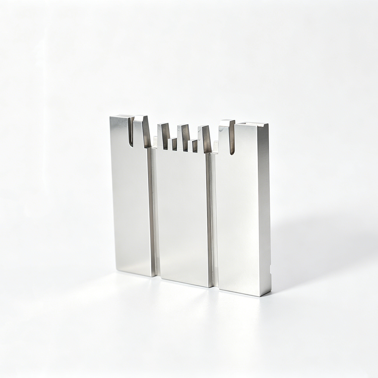
Representative Mold Wear Plate Configurations


Related Mold Wear Plate Components and RFQ





Why Engineering Teams Choose SUUXIANG for Mold Wear Plates
A drawing-driven workflow focused on manufacturability, critical dimensions, coordinated finishing, and inspection evidence before production commitments.
DFM Before Quotation
We review drawing clarity, tool access, datum strategy, and manufacturing risks before aligning the proposed route with your requirements.
Critical Dimensions Prioritized
Critical-to-quality features are identified early so machining, EDM, grinding, and inspection planning follow the dimensions that govern performance.
Coordinated Process Routes
CNC machining, wire or sinker EDM, precision grinding, and fitting are planned as connected operations rather than isolated processes.
Inspection Plan Alignment
Measurement methods, reporting needs, surface priorities, and acceptance criteria are clarified against the drawing before final inspection documentation is prepared.
Revision Visibility
Drawing revisions, manufacturing questions, and delivery coordination remain visible throughout the project to support controlled decisions and traceable communication.
Mold Wear Plates and Precision Component Families
Drawing-driven machining, EDM, grinding, and inspection for configurable mold and tooling components with critical dimensions, wear conditions, and documentation requirements defined before production.

CNC Machining Services
Precision CNC machining services for drawing-based wear plates and related components, planned around material condition, critical dimensions, datum references, tool access, and inspection requirements before production is released.
Upload a Drawing
CNC Milling
Custom CNC milling services for plates, pockets, counterbores, oil grooves, locating features, and mounting patterns. Review machining access, clamping strategy, flatness needs, and finishing stock against the drawing and mating conditions.
Upload a Drawing
CNC Turning
Precision CNC turning services for rotational mold and tooling parts such as bushings, collars, sleeves, pins, and spacers. Diameter relationships, concentricity, shoulder locations, material condition, and secondary-process needs should be defined in the RFQ.
Upload a Drawing
5-Axis Machining
5-axis CNC machining supports complex contours, angled features, deep access requirements, and multi-face geometry with fewer setups where the part design warrants it. Feasibility depends on tool reach, clamping, datum strategy, material, and critical tolerance locations.
Upload a Drawing
Swiss & Micro Machining
Swiss machining and micro machining support small-diameter pins, shafts, sleeves, contacts, and miniature turned features. Drawing review should identify fragile geometry, runout requirements, edge condition, inspection method, material, and the production quantity required.
Upload a Drawing
Wire & Sinker EDM
Wire EDM and sinker EDM services address hardened materials, sharp internal geometry, narrow slots, detailed profiles, and features inaccessible by conventional cutting. Process planning considers wire path or electrode strategy, finish requirements, recast-layer considerations, and inspection points.
Upload a Drawing
Precision Grinding
Precision surface and profile grinding is used when flatness, parallelism, size control, profile accuracy, or surface condition are critical. Grinding stock, heat-treatment sequence, datum surfaces, and measurement method should be agreed before machining begins.
Upload a Drawing
Mold Core & Cavity Inserts
Precision mold core and cavity inserts are manufactured from customer drawings for molding applications requiring controlled parting geometry, cavity detail, cooling-related features, and mating relationships. Material, heat treatment, EDM requirements, finishing scope, and inspection priorities are reviewed per project.
Upload a Drawing
Ejector & Ejection Components
Ejector pins, sleeves, and ejection components are configurable around geometry, fit, wear exposure, and movement within the mold. Define working diameter, guidance relationship, hardness or treatment requirements, surface condition, and any mating-component dimensions for review.
Upload a Drawing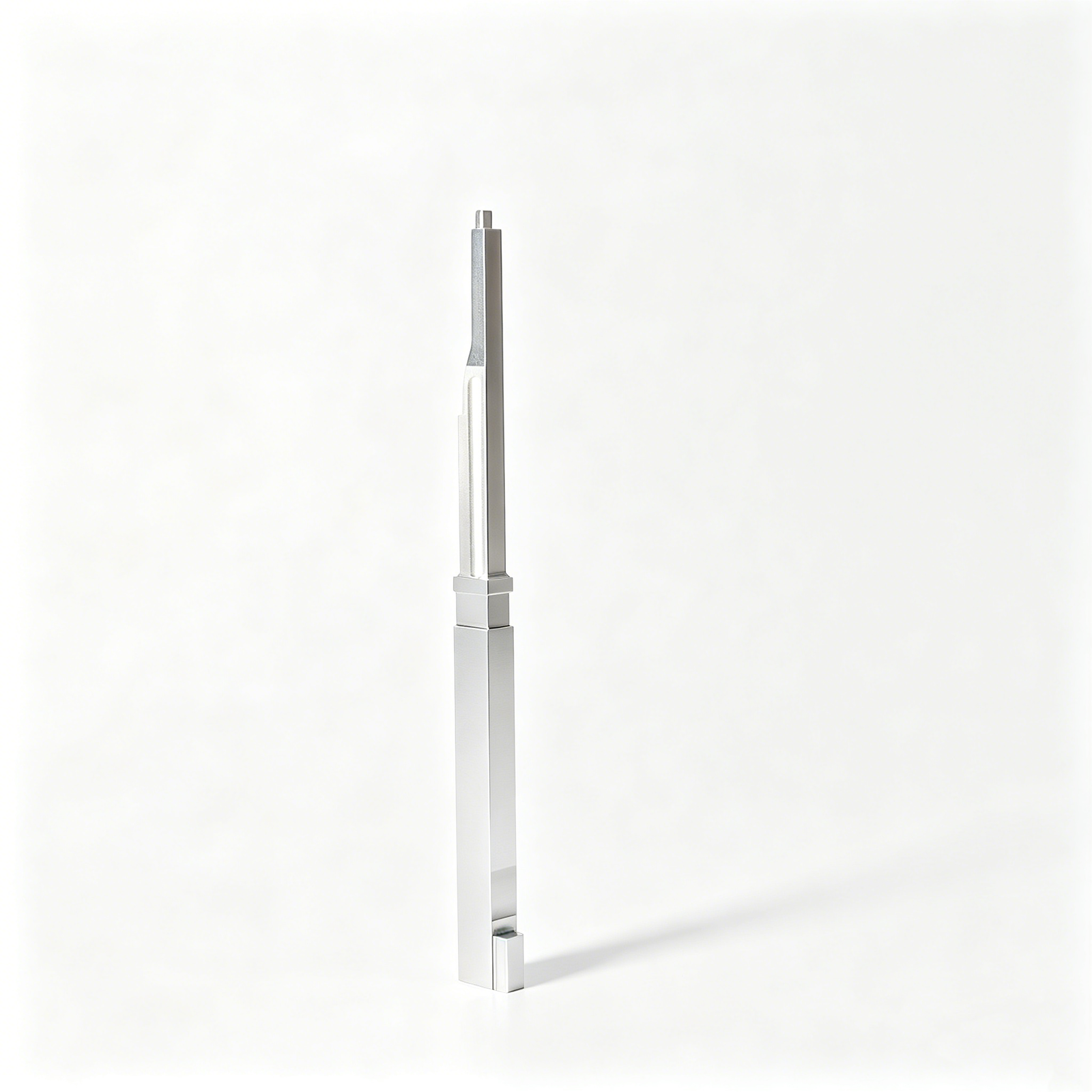
Core Pins, Guide & Locating Components
Core pins, guide pins, and locating components are produced to drawing-defined interfaces that control mold alignment, feature formation, and repeatable assembly. Critical diameter, engagement length, concentricity, material, treatment sequence, and inspection requirements guide the process route.
Upload a Drawing
Slides, Lifters, Gates & Mold Accessories
Mold slides, lifters, gates, and accessories are planned as interacting components rather than isolated shapes. SUUXIANG reviews travel or engagement surfaces, clearance, wear areas, lubrication provisions, machining access, EDM needs, and assembly-related critical dimensions.
Upload a Drawing
Connector Mold Components
Precision connector mold components support fine-pitch, multi-cavity, and high-repeatability connector tooling requirements. Manufacturing review focuses on micro features, pin and cavity relationships, datum control, wear areas, material condition, EDM strategy, and inspection evidence.
Upload a Drawing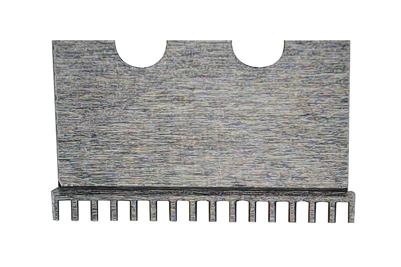
Stamping Die Components
Precision stamping die components can include punches, dies, inserts, guides, plates, and forming-related parts manufactured to the supplied drawing. Material, hardness, clearance relationships, edge condition, grinding allowance, and wear-related surfaces require project-specific review.
Upload a Drawing
Injection, MIM, CIM & Overmolding Tooling
Injection, MIM, CIM, and overmolding tooling components are supported when requirements fall within verified production scope. Drawings should clarify molded material, parting and shutoff conditions, insert interfaces, critical features, treatment requirements, and component-level inspection expectations.
Upload a Drawing
Machining Materials
CNC machining materials are selected against the drawing, application, wear conditions, treatment sequence, corrosion exposure, and machinability. State the required grade or approved alternative, material condition, traceability needs, and any customer-specified certification requirements with the RFQ.
Upload a Drawing
Surface Finishes & Heat Treatment
Surface finishing and heat treatment are coordinated around functional surfaces, wear resistance, corrosion considerations, dimensional movement, and post-treatment grinding or EDM needs. Specify required finish, coating or treatment, surface roughness, masking needs, and verification expectations.
Upload a Drawing
Quality, Metrology & Documentation
Precision inspection, metrology, and quality documentation are aligned with the drawing and agreed inspection plan. Identify critical-to-quality dimensions, datum scheme, sampling or full-inspection expectations, report format, material documentation, revision level, and traceability requirements before production.
Upload a Drawing
Prototyping & Low-Volume Production
Rapid prototyping and low-volume manufacturing support drawing-based evaluation, replacement parts, pilot tooling, and controlled production quantities. An effective RFQ includes the current drawing and model, material, quantity, critical dimensions, quality documentation, revision status, and target delivery date.
Upload a DrawingMaterials for Mold Wear Plates and Guidance Components

Pre-Hardened Tool Steel
A practical choice for general mold wear plates, guide surfaces, and support components where stable machining and moderate wear resistance are required. Confirm supplied hardness, surface finish, and any post-machining stress-relief requirement during review.

Hot-Work Tool Steel
Suitable for demanding sliding components where toughness and thermal stability matter, including molds exposed to repeated temperature cycling. Heat-treatment sequence, grinding stock, and EDM strategy should be defined before final dimensions are committed.

Cold-Work Tool Steel
Used for high-wear guidance and die-contact applications where increased hardness can improve resistance to abrasion. Its harder condition requires careful machining allowance, wire-EDM planning, and controlled finishing of critical sliding faces.


Aluminum Bronze
A bearing-oriented option for sliding interfaces requiring favorable anti-galling behavior against steel mating components. Grade selection, lubrication approach, pocket or groove details, and fit clearances should be evaluated from the application drawing.
Mold Wear Plates: Process Routes

CNC Milling
CNC milling establishes plate profiles, pockets, hole patterns, and reference faces from the approved drawing. Tool access, datum sequence, and machining allowance are reviewed to support stable geometry before downstream finishing.

Wire EDM
Wire EDM is considered for precise internal profiles, narrow slots, and hard-material features where a milling tool cannot achieve the required access. The wire path, start holes, and final stock condition are reviewed with the drawing.

Sinker EDM
Sinker EDM supports deep cavities, sharp internal details, and formed features requiring an electrode strategy. Electrode design, spark allowance, surface requirement, and subsequent finishing needs are defined for the specific component.

Precision Grinding
Precision grinding brings designated faces and thicknesses toward the specified dimensional and surface requirements. Grinding stock, heat-treatment sequence, datum control, and measurement method must be aligned before the finishing route is committed.

Component Fitting
Fitting checks the functional relationship between mold wear plates and their mating slides, guide elements, or moving assemblies when supplied project information supports it. Contact areas and assembly-related priorities remain controlled by the approved revision.

Final Inspection
Final inspection follows the order-specific plan for critical dimensions, datums, surfaces, and reporting requirements. Results and documentation are matched to the approved drawing revision so engineering and quality teams can review traceable evidence.
Configurable Mold Wear Plate Features

Mounting Hole Patterns
Specify through holes, counterbores, tapped holes, and custom patterns for secure installation. SUUXIANG reviews tool access, positional tolerances, datum references, and mating-part requirements before production planning.

Lubrication Grooves
Grooves, pockets, and lubrication passages can be defined for sliding interfaces where the application requires them. Drawing review considers groove geometry, surface intersection, machining sequence, and inspection access.

Locating Features
Add dowel holes, locating slots, shoulders, or reference edges to support repeatable assembly. Critical relationships should identify functional datums so machining and inspection can follow the intended assembly condition.

Surface Finish Requirements
Define bearing surfaces, ground faces, edge breaks, and finish priorities where sliding performance or fit depends on them. The process route can then account for grinding stock, EDM needs, and measurement method.

Part Identification Marks
Part numbers, revision identifiers, orientation marks, and batch references may be added where traceability is needed. Provide marking location, character requirements, and any restrictions on functional or cosmetic surfaces.
About SUUXIANG Mold Wear Plates
SUUXIANG is the sole public-facing brand name of Dongguan SuuXiang Precision Mold Co., Ltd., established in 2010 in Chang’an Town, Dongguan, Guangdong, China. Founded by XiaoCheng Huang, the company supports global engineering and sourcing teams with drawing-driven production of mold wear plates, precision mold components, connector tooling, die components, and custom CNC-machined parts.
Our work brings CNC milling and turning, multi-axis machining, EDM, precision grinding, fitting and inspection into a controlled manufacturing route. Before quotation or production, we review drawings, critical dimensions, datums, material and heat-treatment requirements, machining access, surface expectations and inspection needs.
What distinguishes SUUXIANG is disciplined project communication around manufacturability, revision control and traceable inspection. Rather than treating mold wear plates as a generic catalogue item, we align the process plan with the drawing, application context, quality priorities, quantity and delivery requirements supplied for each project.

How We Manufacture Mold Wear Plates Reliably
DFM and Datum Review
Each mold wear plate project begins with the drawing, mating-part context, material requirement, and critical dimensions. SUUXIANG reviews datum references, mounting interfaces, lubrication features, and tolerance relationships before confirming a practical manufacturing route.
- Identify functional datums and inspection references
- Review hole positions, countersinks, grooves, and edge conditions
- Flag tolerance-stack and assembly risks before production
- Align material, heat-treatment, and surface requirements

CNC, EDM, and Access
Process selection follows geometry and functional requirements rather than a fixed recipe. CNC machining handles accessible profiles and features, while wire EDM or sinker EDM may be considered where internal details, hardened material, or tool access require a different approach.
- Match machining access to part geometry
- Assess wire path and electrode requirements
- Plan feature sequence around heat treatment when applicable
- Maintain drawing revision visibility through routing

Grinding Stock Strategy
Where bearing, sliding, or mating surfaces require finishing attention, SUUXIANG plans grinding allowance and sequence with the specified datums in view. The goal is to protect functional relationships after machining, heat treatment, and finishing operations are evaluated.
- Define surfaces requiring grinding consideration
- Preserve datum relationships during finishing
- Review flatness, parallelism, and thickness requirements
- Coordinate finishing needs with mating components

Inspection and Revision Control
Inspection planning is tied to the order, drawing revision, and agreed critical features. SUUXIANG coordinates measurement expectations, records applicable results, and keeps revision and delivery information visible so mold wear plates can be received against the correct requirements.
- Confirm critical-to-quality dimensions before release
- Select inspection methods appropriate to the feature
- Match documentation to the verified inspection plan
- Control drawing changes before affected production proceeds

Why Choose SUUXIANG for Mold Wear Plates
Compare drawing-driven review and controlled production planning with generic quoting workflows.
← Swipe left or right to view →
Mold Wear Plates: From Drawing to Inspected Parts
A controlled workflow keeps manufacturability, critical dimensions, inspection expectations, and delivery details visible from RFQ through dispatch.
Review RFQ Package
We review drawings, models, material, quantity, application context, delivery target, and inspection requirements to identify missing information before quotation planning begins.
Confirm DFM and Datums
Engineering aligns critical dimensions, datum strategy, tolerance stack, machining access, heat-treatment sequence, and feasible process routes for the requested mold wear plates.
Plan Controlled Manufacturing
The approved revision guides CNC machining, EDM strategy, grinding allowance, fitting needs, and in-process controls appropriate to the component geometry and specification.
Machine, EDM, and Grind
Production follows the planned sequence, combining milling, turning, wire or sinker EDM, grinding, and fitting where required by features, hardness, and surface requirements.
Inspect and Document Results
Parts are checked against the verified inspection plan, with critical dimensions, applicable reporting, revision identity, and order documentation reviewed before release.
Pack and Coordinate Delivery
Released parts are packed for shipment and delivery details are coordinated with the customer, maintaining visibility of order status and final documentation.
How to Source Mold Wear Plates with SUUXIANG
A controlled path from drawing review through approved production and inspection planning.
Submit Your Drawing Package
Provide 2D drawings, 3D models when available, material, quantity, critical dimensions, surface requirements, inspection needs, delivery target, and relevant mating-component or application context.
Review DFM and Quote
Confirm datum strategy, tolerance stack, machining access, heat-treatment sequence, EDM or grinding needs, inspection approach, revision status, commercial scope, and quotation assumptions before commitment.
Approve Samples When Needed
For projects requiring validation, review agreed sample or first-part evidence against the drawing, critical dimensions, surface priorities, fit requirements, and inspection plan before release.
Release Controlled Production
Proceed through the defined CNC machining, EDM, grinding, fitting, and inspection route, with revision control and delivery coordination maintained against the approved order requirements.
Quality Documentation and Certification Review
Customer Feedback on Mold Wear Plates
Reserved for an approved customer reference describing drawing review, process planning, inspection documentation, and a verified project outcome before publication.
Reserved for an approved customer reference with a verified quantity, dimensional requirement, revision-control detail, and documented delivery or inspection result.
Reserved for an approved customer reference covering mold wear plates, material requirements, critical dimensions, and a specific production outcome supported by project records.
Mold Wear Plates FAQ for RFQ Preparation
Practical answers for buyers preparing drawing-based mold wear plate inquiries.
What information should I include in an RFQ for mold wear plates?
Can SUUXIANG quote custom mold wear plates with no standard part number?
What MOQ applies to custom mold wear plates?
Can I order a sample before releasing a larger production quantity?
What tolerances can SUUXIANG hold on mold wear plates?
Which materials are suitable for mold wear plates?
What inspection documents can be requested with an order?
How are drawings, revisions, and IP handled during quotation and production?
The Complete Buyer’s Guide to mold wear plates
Use this decision framework to specify mold wear plates, compare materials and lubrication strategies, evaluate drawing-driven suppliers, control cost and lead time, and avoid fit, tolerance, and premature-wear mistakes.
1. What Are mold wear plates?
In mold and die work, a mold wear plate is a replaceable bearing-and-wear interface between moving members. It carries controlled sliding contact so the mating slide, lifter, cam, or guided assembly is supported and the intended sacrificial surface absorbs wear.
A structural plate primarily carries mold-body stiffness or fastening load, whereas a mold wear plate establishes a defined sliding interface, contact area, and replacement path. It also differs from an abrasion liner, which protects equipment from bulk-material erosion rather than controlling positional motion between precision mating components.
The specification should begin with the motion or failure problem the plate must solve. State whether it guides travel, resists side load, protects a more costly component, stabilizes alignment, or reduces maintenance; then relate that function to drawing datums, mating surfaces, travel path, lubrication approach, and inspection priorities.
2. How Mold Wear Plates Evolved
Steel-on-steel wear interfaces have traditionally depended on applied lubricant, linking bearing-face condition to maintenance discipline and service intervals. As slides, lifters, and cam-driven actions added travel and side load, replaceable bearing faces became preferable to reworking a larger mold member.
Standardized inch and metric component practices made replaceable interfaces more practical. Hole patterns, thickness, datum locations, and mating clearance therefore need to be defined in the design record rather than treated as workshop assumptions.
Aluminum bronze can provide a dissimilar bearing surface where sliding behavior and mating-material compatibility require separate evaluation. Graphite self-lubricating configurations can reduce reliance on routine applied lubrication, but graphite placement must match the loaded travel path and does not replace alignment or clearance control.
3. Types of mold wear plates
Geometry should follow the sliding path and force path before material or finish is selected. The drawing must show the mating member, installed datum, travel direction, contact area, and service-access constraints.
Flat And Rectangular Plates

Two flat faces carry linear sliding loads on mold bases, ejector assemblies, or simple slides. Plate length, width, thickness, mounting holes, and counterbores determine bearing area and replacement access.
One rectangular interface suits straight travel when the load remains normal to the contact face. Specify the working face, relief edges, mating-surface finish, and datum-to-hole relationships.
Gibs, Angles, And Heels
Two opposed gib or side plates constrain lateral slide motion along a guided sidewall. Side clearance, preload method, fastening direction, and lubrication access affect seizure risk.
One angle or heel plate resists closing or side-thrust loads at an inclined interface. Define angle, projected contact length, stop position, and whether impact occurs before full clamp.
Cam, Guided, And Custom Plates
Two cam-dwell faces manage travel where a cam enters, dwells, or returns. Show cam path, dwell location, contact timing, thrust direction, and allowable edge break.
One contoured or quick-change plate fits nonrectangular contact or planned maintenance replacement. Provide the 3D mating geometry, keying features, extraction method, interchangeability datum, and revision-controlled hole pattern.
4. Materials for mold wear plates
Material choice starts with contact pressure, stroke speed, lubrication access, and the mating surface. Tool steel, aluminum bronze, and graphite-equipped configurations should be evaluated against the application rather than selected as interchangeable defaults.
| Material | Strengths | Limitations | Typical Application | Lubrication Need |
|---|---|---|---|---|
| Hardened tool steel | High load resistance | Galling risk | Guides and slides | Regular oil or grease |
| Pre-hardened steel | Machinable, stable | Lower wear resistance | Moderate-duty plates | Regular oil or grease |
| Aluminum bronze | Anti-galling, corrosion resistance | Softer than steel | Steel-mating slides | Recommended |
| Graphite-plugged bronze | Intermittent lubrication | Plug wear, higher cost | Limited-access slides | Reduced external access |
| Coated steel or carbide | Abrasion resistance | Cost, difficult finishing | Verified severe duty | Application-dependent |
Match The Sliding Pair
Hardened tool steel suits high-load, well-lubricated steel-on-steel guidance, but similar hardness can gall when oil supply fails. Pre-hardened steel machines more easily and suits moderate-duty plates where post-machining hardening is undesirable.
Use Bronze Strategically
Aluminum bronze provides a dissimilar mating surface that helps reduce steel-on-steel galling and offers useful corrosion resistance. Graphite-plugged bronze is justified where grease access is intermittent, though plugs do not replace clearance, alignment, or contamination control.
5. Custom mold wear plate Options
The 2D drawing should convert sliding load, travel, lubrication, and mounting constraints into manufacturable plate requirements. SUUXIANG reviews those inputs before selecting a CNC, EDM, grinding, and inspection route.
Define The Functional Envelope

Overall length, width, thickness, hole patterns, counterbores, dowel features, relief pockets, radii, and edge breaks should be dimensioned from identified datums. The drawing should distinguish mounting faces from the running wear face and state accessible tool paths.
Specify Surface And Lubrication
The running face should state its surface-finish requirement, oil-groove geometry, or graphite plug layout rather than relying on a visual description. Heat treatment and coating requirements need sequence notes, because finishing, grinding stock, and final inspection may depend on them.
Control Interfaces And Evidence
Critical dimensions need explicit tolerances, datum references, geometric controls where required, and a stated inspection method. Matched mating components should be supplied as drawings or models so SUUXIANG can review clearance, contact pattern, fit, marking, revision level, and reporting expectations.
6. Critical Quality and Construction Details
A wear plate is accepted as part of a sliding system, not as an isolated rectangle. Its bearing face, mounting features, and lubrication details must preserve the intended relationship with the mating slide or guide.
Bearing Geometry
Flatness, parallelism, and finished thickness should be controlled from functional datums identified on the drawing. A bowed plate or thickness variation shifts contact toward an edge, raising local load and accelerating wear on both mating surfaces.
- Specify flatness across the bearing face.
- Specify parallelism to the mounting datum.
- Define thickness tolerance after finishing.
Mounting And Edges
Hole location and positional tolerance should reference the same datum scheme used by the mold plate or guide. Burr-free holes, countersinks, and edges prevent false seating, trapped debris, and interference during assembly or slide travel.
- State hole diameter and positional tolerance.
- Define counterbore or countersink geometry.
- Require burr removal without rounding bearing edges.
Lubrication And Verification
Heat treatment can distort geometry, so grinding stock, final inspection timing, and hardness requirements belong in the process plan. For graphite plugs or lubrication grooves, specify pattern, depth, retention, and exclusion from critical bearing edges; record measured results by revision and inspection method.
- Inspect final geometry after heat treatment.
- Confirm graphite plugs are securely retained.
- Identify measuring equipment and report format.
7. How to Choose a Manufacturer
Three documents should anchor supplier selection: controlled 2D drawing, 3D model, and specification sheet. Ask bidders to identify datums, critical dimensions, material condition, and inspection method before pricing.
Evaluate Engineering Review
One drawing review should return a marked-up plan for tool access, grinding stock, EDM features, and heat-treatment sequence. A capable team flags ambiguous tolerances rather than silently assuming them.
Verify Records And First Articles
Each material lot should link to the order, material certificate, heat-treatment record when required, and final inspection report. Request a first article or sample part before releasing a low-volume batch.
Test Communication Discipline
Two response tests expose project discipline: submit a controlled revision and a hypothetical nonconformance. Confirm acknowledgement, containment, corrective-action format, serialized packaging, and protection of ground faces in transit.
8. Common mold wear plate Mistakes
Two early decisions—material pairing and lubrication—often determine whether a plate runs smoothly or galls. One complete drawing review should expose these risks before machining begins.
Material And Lubrication Mismatch
One hardness value is not a material-selection method: incompatible mating surfaces can gall or wear prematurely. Specify both contact materials, load direction, lubricant or self-lubricating design, and maintenance access.
Two dry-running surfaces may bind even when each meets its own hardness requirement. Confirm the lubrication path, groove placement, and contamination exposure with the mold designer.
Unclear Geometry And Finish
One missing datum can move a plate relative to its mating slide, causing assembly delay or uneven contact. Define functional datums, mounting references, thermal growth assumptions, and assembly clearance.
Two uninspectable tolerances create disputes rather than control. Tie each critical tolerance and surface-finish requirement to an accessible inspection method and measurement datum.
Approval Without First-Article Evidence
One approved quotation does not verify the produced interface. Before release, review first-article dimensions, material and heat-treatment evidence when specified, surface results, and fit against mating components.
Two revision states must never be mixed. Require the drawing revision, inspection plan, and acceptance record to match the purchase order before production approval.
9. Steps to Launch a Plate Program
A controlled launch reduces the risk that a correctly machined plate fails in an unverified slide condition. Start with the motion, load direction, contact area, cycle environment, and mating component—not a catalog description.
Define The Working Condition
First, document travel, side load, contact geometry, temperature, lubricant access, and expected duty cycle. Identify the mating material and the datum surfaces that govern fit.
Issue A Controlled RFQ
One released 2D drawing and revision identifier should govern the RFQ; attach the 3D model when available. State quantity, material and heat treatment, surface requirements, critical dimensions, inspection reports, target date, application context, and shipping destination.
Close The Production Loop
Before release, request DFM feedback on tool access, EDM or grinding requirements, and proposed inspection method. Align quote assumptions, approve material evidence and first article, validate tool fit, then define repeat-order revisions and spare-part quantities.
10. Mold Wear Plate Pricing and Lead Times
1-piece orders usually carry the highest setup cost per plate because programming, fixturing, and first-piece verification are spread over few parts. All price and lead-time ranges below are illustrative, quote-dependent planning guidance—not market promises or SUUXIANG commitments.
6 inputs make quotes comparable: released 2D drawing and 3D model, material and heat-treatment specification, quantity, critical dimensions and datums, surface/graphite requirements, and delivery plus inspection-report needs. Setup, stock size, heat treatment, graphite pocket processing, tight tolerances, inspection scope, and freight can change both cost and timing.
| Order tier | Complexity / material family | Inspection requirement | Illustrative lead-time range | Relative price driver |
|---|---|---|---|---|
| 1–5 pieces | Simple steel plate | Dimensional check | Quote-dependent | High setup share |
| 10–50 pieces | Ground tool steel or bronze | Report on critical dimensions | Quote-dependent | Material and grinding |
| 50+ pieces | Graphite-bearing bronze or complex EDM features | First article plus agreed report | Quote-dependent | Graphite, EDM, inspection |
Upload Your Drawing for Mold Wear Plates RFQ
Include 2D and 3D files, material, quantity, critical dimensions, inspection needs, and target delivery date for engineering review.