
Precision Stamping Die Components, Reviewed Before Machining
Send your drawing for DFM, critical-dimension review, and an inspection-focused manufacturing route for custom precision stamping die components.
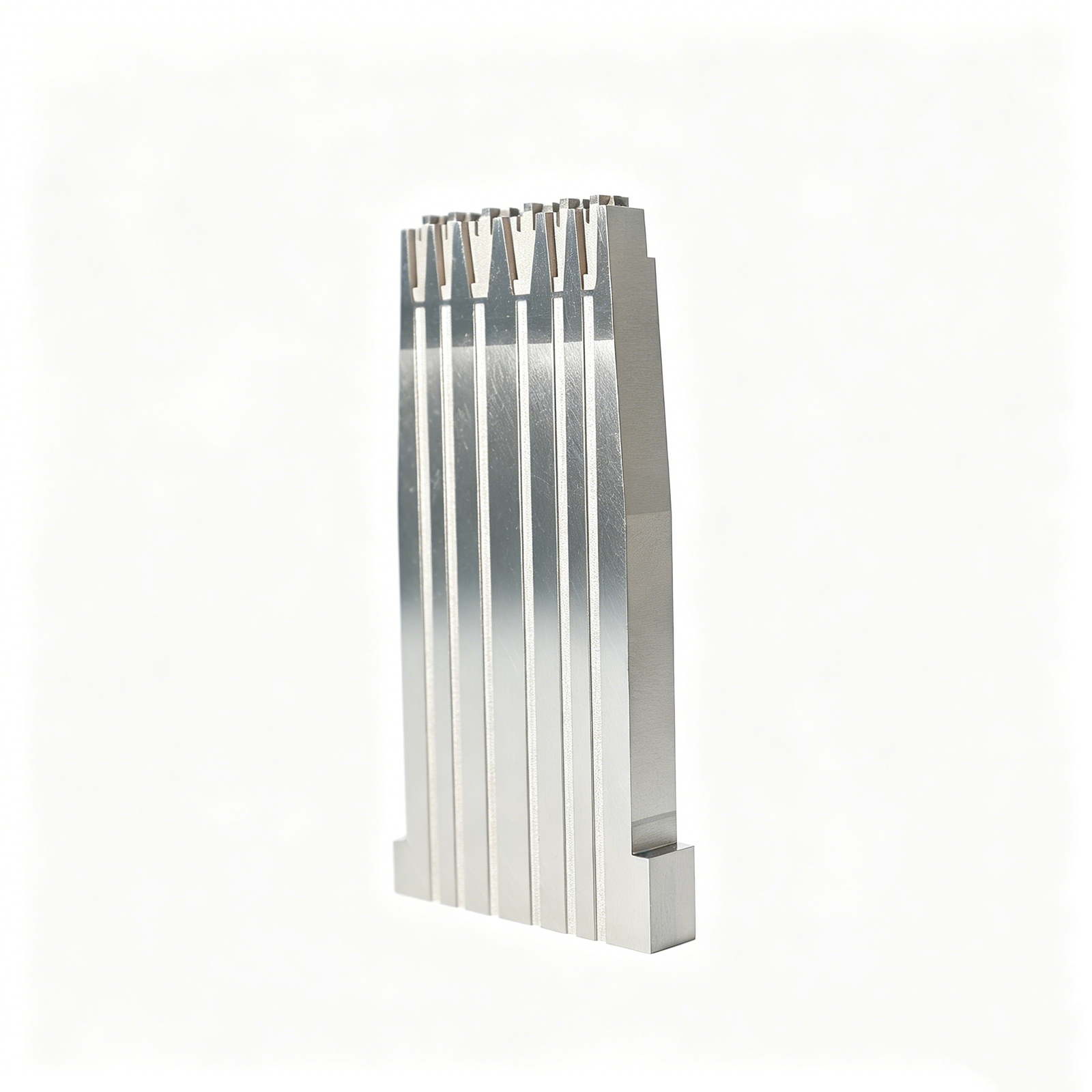
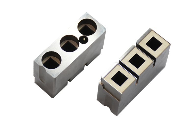
Representative Precision Stamping Die Components









Related Drawing-Based Components and RFQs




Engineering Advantages for Precision Stamping Die Components
A drawing-led approach that clarifies manufacturability, process sequencing, inspection priorities, and revision requirements before production commitments.
DFM Before Commitment
Review critical dimensions, datums, tool access, material requirements, and heat-treatment sequence before quotation and production planning.
Coordinated Process Routes
Plan CNC machining, wire or sinker EDM, grinding, and fitting around geometry, access constraints, and functional mating conditions.
Inspection-First Planning
Define inspection methods and reporting expectations around critical-to-quality features, surface requirements, and agreed drawing revisions.
Revision Visibility
Keep drawing changes, manufacturing questions, and delivery information visible so the approved requirement remains clear throughout the project.
Technical RFQ Communication
Provide drawings, models, quantities, quality needs, and target dates to support a focused technical discussion for precision stamping die components.
Precision Stamping Die Components and Custom Part Families
Drawing-driven process routes for configurable tooling components, critical interfaces, and custom machined details requiring controlled inspection and revision traceability.

CNC Machining Services
Precision CNC machining services for drawing-based die components and custom details. Review focuses on material, datums, critical dimensions, tool access, machining sequence, and inspection requirements before production commitments are made.
Upload a Drawing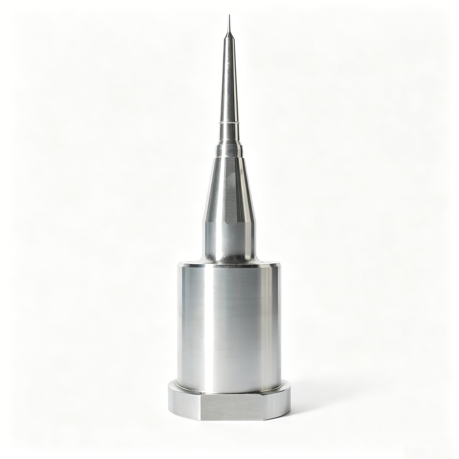
CNC Milling
Custom CNC milling services for plates, inserts, forming details, and complex die features. Toolpath planning considers clamping, cutter reach, corner geometry, stock allowance, and dimensions requiring in-process or final verification.
Upload a Drawing
CNC Turning
Precision CNC turning services for rotational die components such as punches, bushings, guide elements, and custom pins. Diameters, concentricity, shoulders, threads, and datum relationships should be defined clearly on the drawing.
Upload a Drawing
5-Axis Machining
5-axis CNC machining supports multi-face features, angled geometry, and complex component access with fewer setups where appropriate. Feasibility depends on part geometry, workholding, cutter reach, tolerance strategy, and inspection access.
Upload a Drawing
Swiss & Micro Machining
Swiss machining and micro machining support small-diameter, high-detail components where handling, runout, feature spacing, and inspection method require careful planning. Submit functional dimensions, material condition, quantity, and mating-part context with the RFQ.
Upload a Drawing
Wire & Sinker EDM
Wire EDM and sinker EDM services address hardened profiles, narrow slots, sharp internal geometry, and features beyond conventional cutter access. The process route should define wire paths, electrode strategy, finish requirements, and any recast-layer considerations.
Upload a Drawing
Precision Grinding
Precision surface and profile grinding is used to control flatness, parallelism, profile accuracy, and functional fit after machining or heat treatment. Drawings should identify grinding datums, stock allowance, surface requirements, and critical inspection points.
Upload a Drawing
Mold Core & Cavity Inserts
Precision mold core and cavity inserts are configured from drawings around material, heat-treatment sequence, shutoff geometry, cooling or feature access, and mating interfaces. Review confirms critical dimensions, EDM needs, grinding stock, and inspection plan.
Upload a Drawing
Ejector & Ejection Components
Ejector pins, sleeves, and ejection components are produced to the functional relationship between moving elements, plates, bores, and molded-part requirements. Specify material, hardness condition, diameter tolerances, surface needs, and mating dimensions.
Upload a Drawing
Core Pins, Guide & Locating Components
Core pins, guide pins, and locating components require controlled relationships between locating surfaces, diameters, shoulders, and assembly datums. Drawing review helps identify fit class, wear considerations, heat treatment, grinding sequence, and verification method.
Upload a Drawing
Slides, Lifters, Gates & Mold Accessories
Mold slides, lifters, gates, and accessories are configurable tooling details requiring attention to motion, shutoff surfaces, clearance, wear areas, and assembly interfaces. Provide the relevant section views, mating components, material requirements, and critical functional dimensions.
Upload a Drawing
Connector Mold Components
Precision connector mold components support tightly spaced cavity features, pin and insert interfaces, and repeatable alignment within connector tooling. Manufacturability review addresses micro features, EDM or grinding requirements, material condition, and inspection accessibility.
Upload a Drawing
Stamping Die Components
Precision stamping die components include punches, dies, inserts, guide elements, forming details, and custom wear parts. Production planning considers strip interaction, clearance-sensitive geometry, material and heat treatment, grinding allowances, and critical functional dimensions.
Upload a Drawing
Injection, MIM, CIM & Overmolding Tooling
Injection, MIM, CIM, and overmolding tooling components are evaluated as drawing-driven manufacturing work within verified scope. Review covers molded-material context, interfaces, shrinkage-related requirements, venting or gate features, material selection, and inspection expectations.
Upload a Drawing
Machining Materials
CNC machining materials are selected against drawing requirements, application loads, wear, corrosion exposure, machinability, heat-treatment sequence, and availability. State the exact grade or approved equivalent, material condition, certification needs, and any restrictions in the RFQ.
Upload a Drawing
Surface Finishes & Heat Treatment
Surface finishing and heat treatment are planned around functional surfaces, wear resistance, corrosion needs, dimensional change, and subsequent grinding or EDM operations. Define required process, hardness range where applicable, masking, finish limits, and verification documentation.
Upload a Drawing
Quality, Metrology & Documentation
Precision inspection, metrology, and quality documentation are aligned to the drawing’s critical dimensions, datums, tolerances, and reporting requirements. Agree inspection method, sampling expectations, report format, material evidence, and revision status before production begins.
Upload a Drawing
Prototyping & Low-Volume Production
Rapid prototyping and low-volume manufacturing support drawing validation, fit checks, tooling trials, engineering changes, and controlled supply of custom parts. Include quantity, material, critical dimensions, quality documentation, and target delivery requirements for a realistic review.
Upload a DrawingMaterials Considered for Precision Stamping Die Components

D2 Tool Steel
A common choice for cutting inserts, punches, and wear-focused precision stamping die components. Its high-carbon, high-chromium structure supports wear resistance after heat treatment, while machining and EDM planning should account for final grinding stock.

H13 Tool Steel
Often evaluated for tooling exposed to repeated impact, thermal cycling, or demanding forming loads. H13 offers a useful toughness and heat-resistance balance, but the specified hardness, heat-treatment route, and finish requirements must be reviewed together.

M2 High-Speed Steel
Suitable for selected punch and cutting applications where hot hardness and edge retention matter. Its higher alloy content can affect machining strategy, heat-treatment control, and grinding requirements, so service conditions should be defined in the RFQ.

Cemented Carbide
Considered for high-wear cutting and forming areas requiring exceptional hardness and wear resistance. Carbide can be brittle and requires suitable support, geometry, and EDM or grinding methods; application loads and mating-material details guide feasibility review.

Prehardened Alloy Steel
Used for selected die plates, retainers, support blocks, and structural components when the drawing calls for stable strength without a final hardening cycle. Machining access, threaded features, and datum surfaces are reviewed before process planning.
Precision Stamping Die Components: Machining, EDM, Grinding and Fitting


Wire EDM
Wire EDM produces precise through-profiles, narrow slots and intricate contours where conventional cutting access is limited. Wire-path planning, datum location and finishing requirements are reviewed against the drawing before the machining route is confirmed.

Sinker EDM
Sinker EDM supports internal forms, sharp details and difficult-to-reach geometries that require an electrode strategy. Electrode design, spark clearance and surface requirements are evaluated alongside the material and subsequent finishing operations.


Fitting Inspection
Fitting verifies mating relationships where individual precision stamping die components must work together. Inspection methods and reporting are aligned with critical dimensions, functional interfaces, revision status and the quality expectations provided with the RFQ.
Supporting Accessories for Precision Stamping Die Components

Guide Pins
Guide pins support repeatable alignment between mating die sections. Confirm the locating relationship, running fit, material condition, mounting method, and inspection dimensions against the die drawing and intended press application.

Guide Bushings
Guide bushings pair with guide pins to control guided movement within the die assembly. Drawing review should establish bore geometry, retention details, lubrication needs, wear considerations, and the critical alignment datum.

Dowel Pins
Dowel pins provide positive location for inserts, plates, and replaceable details during assembly. Define pin diameter, engagement depth, fit callouts, installation sequence, and the datum scheme that controls component position.

Retainer Plates
Retainer plates hold punches, inserts, or supporting details in their specified positions. Their pocket geometry, fastening pattern, clearance requirements, and relationship to serviceable components should be confirmed during DFM review.

Ejection Components
Ejection-related components help release formed material or tooling details where the application requires controlled movement. Review travel, contact surfaces, return method, load path, clearance, and mating-part constraints from the drawing.
About SUUXIANG Precision Stamping Die Components
SUUXIANG is the sole public-facing brand of Dongguan SuuXiang Precision Mold Co., Ltd. Founded by and legally represented by XiaoCheng Huang, the company was established in 2010 and is based on the 2nd Floor of Sanhe Industrial Park, Chang’an Town, Dongguan, Guangdong, China. We help international engineering, sourcing, and quality teams turn drawings and specifications into inspected custom parts, mold components, connector tooling, and precision stamping die components.
Our work brings CNC milling and turning, multi-axis machining, EDM, precision grinding, fitting, and inspection into a controlled manufacturing workflow. Before quotation and production commitments, we review drawing details, critical dimensions, datums, material requirements, machining access, and inspection expectations to clarify the appropriate process route.
What distinguishes SUUXIANG is disciplined project communication around the details that affect part performance and acceptance. We keep revision status, process planning, and inspection requirements visible while coordinating drawing-based work, helping buyers evaluate manufacturability and prepare an RFQ with the evidence needed for a responsible production decision.

Core Capabilities Behind Precision Stamping Die Components
DFM Before Commitment
SUUXIANG reviews the drawing, model, material, quantity, critical dimensions, datums, and surface requirements before quoting precision stamping die components. The discussion identifies tolerance-stack risks, tool access, heat-treatment sequence, and inspection evidence needed for a responsible production plan.
- Confirm critical-to-quality dimensions and datum references
- Identify machining access and practical feature geometry
- Align material, heat treatment, and surface requirements
- Define inspection priorities before production begins

CNC and Multi-Axis Planning
Complex die details require a process route matched to geometry, not a generic machining promise. CNC milling, turning, multi-axis work, and micro-machining are evaluated against wall conditions, feature reach, clamping strategy, and the relationship between mating precision stamping die components.
- Review setup access for pockets, profiles, and side features
- Plan clamping around protected functional surfaces
- Assess feature size, depth, and cutter reach
- Coordinate mating dimensions across related components

EDM and Grinding Strategy
Wire EDM, sinker EDM, and precision grinding are planned where hardened material, internal geometry, fine profiles, or controlled finish make them appropriate. SUUXIANG considers electrode strategy, wire path, grinding stock, and sequencing so final dimensions are assessed after the relevant operations.
- Determine when EDM is preferable to conventional cutting
- Review wire-entry, flushing, and profile-access needs
- Reserve grinding allowance for critical finished faces
- Sequence heat treatment and finishing around dimensional risk

Inspection and Revision Control
Inspection planning links the drawing’s critical features to a defined measurement method and the order’s documentation needs. Revision-controlled communication keeps changes visible as precision stamping die components move through machining, finishing, fitting, and final verification for delivery coordination.
- Match inspection methods to critical dimensions and datums
- Clarify report, traceability, and documentation requirements
- Keep drawing revisions visible throughout production
- Confirm final records against the verified inspection plan

Why Choose SUUXIANG for Precision Stamping Die Components
A drawing-based workflow that puts DFM, critical dimensions, process planning, inspection and revision visibility before production commitments.
← Swipe left or right to view →
Precision Stamping Die Components: From Drawing Review to Delivery
A drawing-driven workflow that keeps manufacturability, critical dimensions, inspection requirements, and revision status visible before shipment coordination.
RFQ and Drawing Intake
Submit 2D drawings, 3D models when available, material, quantity, application context, quality requirements, and target delivery date for an informed technical review.
DFM and Critical Review
SUUXIANG reviews datums, critical dimensions, tolerance stack, tool access, heat-treatment sequence, EDM needs, grinding allowance, and inspection expectations before production commitments.
Process Route Planning
The project team defines the appropriate CNC, multi-axis, turning, wire EDM, sinker EDM, grinding, fitting, and control sequence for the approved drawing revision.
Machining and EDM Execution
Precision stamping die components are machined through the planned operations, with electrode strategy, wire paths, machining allowances, and revision information controlled throughout production.
Grinding Fitting and Inspection
Grinding and fitting address functional interfaces, while inspection follows the agreed plan for critical dimensions, surface requirements, and documentation associated with the order.
Packing and Shipment Coordination
After final verification, parts are packed for the component geometry and shipment requirements, with delivery coordination and order documentation aligned to the confirmed project scope.
Start Your Precision Stamping Die Components Project
Give SUUXIANG the technical context needed to review manufacturability, align inspection expectations, and prepare a controlled production release.
Submit Your Drawing
Send the 2D drawing, available 3D model, application context, material requirement, quantity, and target delivery date for an initial technical review.
Confirm Critical Requirements
Identify critical dimensions, datums, surface requirements, heat-treatment sequence, mating conditions, and required inspection records before quotation or production commitments are made.
Review the Process Plan
Discuss practical DFM findings, machining access, EDM or grinding needs, inspection methods, revision status, and any sampling or approval requirement for your precision stamping die components.
Release Production Clearly
Approve the agreed drawing revision, process assumptions, quality expectations, quantity, and delivery plan so manufacturing and final documentation remain aligned with the order.
Quality Documentation and Certification Review
Precision Stamping Die Components: Customer Feedback and Project Outcomes
Customer feedback will be published only after approval and verification of the relevant project outcome.
Reserved for an evidence-supported case study covering critical dimensions, revision coordination, and the verified delivery result for a drawing-based tooling project.
Reserved for verified feedback on machining, EDM, grinding, and inspection planning for a custom stamping-die component order.
Precision Stamping Die Components FAQ
Practical answers for teams preparing a drawing-based tooling-component RFQ.
What should I include in an RFQ for precision stamping die components?
Can SUUXIANG quote low-volume precision stamping die components?
How do you review drawings for precision stamping die components before production?
Can I order samples before placing a larger tooling-component order?
How is lead time evaluated for custom stamping die parts?
What inspection reports are available for precision stamping die components?
How are drawing revisions controlled during a custom component order?
How are payment, shipping, and confidential drawings handled?
The Complete Buyer’s Guide to precision stamping die components
Use this decision framework to specify components, compare materials and manufacturing controls, assess qualified suppliers, and avoid cost, tolerance, and validation mistakes before releasing drawing-based tooling parts.
1. What Are precision stamping die components?
One complete stamping die is an assembly; precision stamping die components are its individually specified, drawing-based elements, not the stamped production part. They include the parts that create or control the working relationship inside the tool.
Six functional roles commonly define these components: cutting and forming metal, locating and guiding strip, stripping material from punches, and retaining working details in position. A punch, die insert, pilot, guide element, stripper, retainer, or locating detail must fit its mating interfaces as a system.
Two controlled inputs—the 2D drawing and mating-component context—should accompany the RFQ, with the 3D model when available. Specify tolerances, datums, material, hardness or heat-treatment requirement, production application, and inspection priorities; an error in location, clearance, profile, or surface condition can affect alignment, strip control, cut quality, wear, and die maintenance.
2. How Precision Die Components Evolved
Two manufacturing shifts changed die-component sourcing: standardized guide elements made common interfaces easier to replace, while per-print details remained toolroom work. Early components depended heavily on manual layout, jig work, hand fitting, and local knowledge, so interchangeability was limited by the individual die build.
Three digitally controlled routes now divide much of the work: CNC machining establishes accessible geometry, wire EDM produces through profiles, and sinker EDM creates internal or difficult-access features. Heat treatment, grinding, and planned inspection then control the condition and dimensions that machining alone may not preserve.
One shared 2D drawing, 3D model, datum scheme, and revision record can let international teams source complex precision stamping die components across borders. Tight corner radii, thin sections, mating clearances, wear surfaces, and post-heat-treatment geometry still require engineering review of tool access, EDM strategy, grinding stock, and inspection method before release.
3. Types of precision stamping die components
Six component families determine how a stamping die cuts, forms, aligns, holds, and releases strip. Source each as a defined interface, not a generic replacement part.
Punches And Forming Punches
Punches shear or form material against a mating die opening. Tip clearance, profile, and shank retention drive breakage risk; provide section views, datums, and edge requirements.
Die Buttons Blocks And Inserts

Die buttons, blocks, and inserts receive the punch or support formed stock. Mating clearance and seat location govern burrs or cracking; specify profiles, pocket fits, material, and replaceable interfaces.
Guide Pins And Bushings
Guide pins and bushings align upper and lower die members. Running fit and concentricity affect misalignment wear; show center distances, mounting details, stroke relationship, and lubrication provisions.
Strippers Pads And Retainers

Strippers remove strip from punches, while pads control stock and retainers locate working details. Insufficient travel or retention can bend punches; define preload, travel, contact faces, and fastening locations.
Springs Ejectors And Fasteners
Springs create return force, ejectors release parts, and fasteners secure assemblies. Force mismatch or loosening disrupts timing; state installed height, travel, force class, thread, and locking method.
Wear And Locating Details
Wear plates, keys, heels, pilots, and custom locators resist side load or position strip. Galling and tolerance-stack error are common; provide mating materials, clearance, datum scheme, and replacement criteria.
4. Materials for precision stamping die components
D2, H13, M2, carbide, and stainless serve different loading and wear conditions. For precision stamping die components, select the working surface separately from its supporting holder.
| Material | Typical Application | Primary Trade-Off |
|---|---|---|
| D2 tool steel | Abrasion-prone punches and inserts | Wear resistance; lower shock tolerance |
| H13 tool steel | Impact or thermal-cycling details | Toughness; lower abrasive-wear resistance |
| M2 high-speed steel | High-load cutting edges | Hardness; treatment control required |
| Carbide | Abrasive strip or long-run inserts | Service life; brittle and costly |
| Stainless or aluminum bronze | Corrosive or sliding wear interfaces | Environment control; application-specific strength |
Match Material To Failure Mode
D2 commonly suits abrasion-dominant inserts; H13 favors shock and thermal cycling. Carbide resists severe abrasive wear but needs rigid support and tolerates impact poorly.
The Fabricator identifies hardenable tool steels and carbide for cutting and forming sections: https://www.thefabricator.com/thefabricator/article/bending/die-basics-101-starts-with–eight-basic-components
Specify Treatment And Repair Strategy
Heat treatment should state hardness range, distortion allowance, and post-treatment grinding datum. Coatings require a stable substrate and compatible edge preparation.
Stainless grades suit corrosion exposure; aluminum bronze can provide a dissimilar sliding wear face that reduces galling. Higher initial cost must be weighed against repairability and service life.
5. Custom Features, Finishes, and Coatings
Each custom feature should resolve a defined stamping, assembly, inspection, or maintenance need. For precision stamping die components, geometry and finish must be specified from functional contact conditions, not appearance.
| Feature | Primary Function | Specification Question |
|---|---|---|
| Relief or radius | Release and clearance | What tool access is required? |
| Ground or lapped face | Fit and friction control | Which datum controls contact? |
| Coating | Wear reduction | What mating material and lubrication apply? |
Functional Geometry
Reliefs and radii provide chip escape, reduce stress concentration, and prevent interference during assembly or stripping.
Datum holes, dowel locations, threads, and access holes should reference the assembly datum scheme so replacement parts locate consistently.
- Specify minimum tool access
- Define controlled radii
- Identify serviceable fasteners
Finish By Contact
Surface grinding establishes flatness and controlled fitting faces. Polishing or lapping is appropriate where sliding contact, release, or sealing depends on lower friction and surface consistency.
Laser marking can retain part number, revision, and orientation where it remains visible after assembly.
Coating Selection
Wear-reducing coatings require review of the mating strip material, lubrication, contact pressure, and forming mode. A coating that improves abrasive-wear resistance may not solve galling or edge chipping.
Trial evidence should confirm coating adhesion, dimensional allowance, and rework method before release.
6. Quality Elements in precision stamping die components
Two fit-related dimensions can matter more than dozens of general dimensions. For precision stamping die components, quality begins by tying functional features to stable datums and defining the clearance each mating part requires.
Functional Datum Strategy
Three datum references should locate a component consistently: a primary seating face, secondary side face, and tertiary locating feature. Position, perpendicularity, and concentricity should protect the punch, insert, or guide function—not tighten every nonfunctional surface.
Edge And Surface Requirements
Edge condition and surface finish can materially affect seating, strip flow, and assembly on small features. Specify the controlled edge condition, surface-finish direction, and any break-edge limit; separate working faces from cosmetic or nonmating surfaces.
Inspection After Heat Treatment
100% measurement is not automatically the right control plan; critical dimensions and geometric controls should drive CMM, optical, or calibrated bench-gage selection. Hardness verification and first-article records should confirm the approved heat-treatment sequence has not distorted datums, bores, or mating clearances.
7. How to Choose a Component Manufacturer
A capable supplier turns a drawing into a controlled process, not merely a quotation. Evaluate precision stamping die components against project-specific evidence before releasing an order.
Review The DFM Response
One drawing review should identify CTQ dimensions, datum logic, tool access, EDM or grinding needs, and unresolved assumptions.
Two questions matter: Which features drive risk, and what revision is being quoted? Request marked-up drawings and a documented revision register.
Verify Process And Material Control
Three process routes—CNC machining, EDM, and grinding—should be linked to features, allowances, and inspection points.
One material record and one heat-treatment record should match the order when specified. Request material identification, process sequence, and applicable inspection evidence.
Test Project Execution
One prototype order can reveal communication discipline, packaging protection, and responsiveness to deviations before low-volume release.
Two practical questions are: Who owns corrective action, and what report follows a nonconformance? Request a sample inspection report, packing method, and corrective-action workflow.
8. Common Buyer Mistakes to Avoid
Two recurring RFQ gaps create avoidable risk before machining starts: ambiguous design intent and incomplete verification planning. For precision stamping die components, clarify those inputs before comparing quotations.
Define Drawings And Datums
A 2D drawing without functional datums or tolerance rationale can produce parts that inspect acceptably yet misfit in the die. Identify CTQ features, datum order, mating interfaces, and permissible geometric variation.
A missing revision identifier invites rework when several files circulate. Issue one controlled drawing package with revision, 3D model status, and a written change log.
Specify Material And Mating Conditions
A material callout without grade, hardness condition, or heat-treatment sequence can cause premature wear or distortion. State the required condition and confirm whether final grinding follows heat treatment.
A punch specified alone cannot establish clearance or alignment with its die button, stripper, or guide. Provide mating-component drawings and relevant strip-material context.
Buy Evidence, Not Price
A lowest-price comparison can omit EDM, grinding, fitting, inspection, or traceable documentation, then surface as delay or inconsistent stamping. Compare process route, exclusions, delivery assumptions, and inspection evidence line by line.
A first article left unapproved transfers design risk into production. Define sample quantity, acceptance criteria, measurement method, and approval record before release.
Plan Inspection And Delivery
An RFQ without inspection requirements may receive measurements that do not cover functional features. Name the report format, sampling expectation, datum setup, and any required material or heat-treatment records.
A delivery plan that ignores packaging, customs documents, and revision cut-off dates can disrupt assembly. Confirm shipment terms, protection for finished edges, and the effective revision before dispatch.
9. Launching a precision stamping die components Project
One complete RFQ prevents quotation assumptions from becoming shop-floor rework. For precision stamping die components, align the drawing, model, mating context, critical dimensions, and acceptance evidence before material is released.
RFQ And DFM Review
One engineering review should confirm datums, tolerances, material, heat treatment, surface finish, wire paths, EDM features, and grinding allowance. Program owners should identify revision authority, required quantity, and target delivery date.
Quote And First Article
Before purchase order release, procurement should reconcile scope, quantity, commercial terms, and any quoted exclusions with the controlled revision. Quality should approve the first-article plan, measurement methods, report format, and disposition path for nonconforming results.
Release, Shipment, And Feedback
At production release, engineering confirms that the approved first article represents the build configuration. Quality verifies final inspection records; procurement confirms packaging, shipment documents, and feedback on fit, function, and revision changes.
- Controlled 2D drawing and 3D model
- Material, heat-treatment, and finish requirements
- CTQ dimensions, datums, and inspection report criteria
- Quantity, delivery date, packaging, and shipment instructions
10. Precision Stamping Die Component Pricing
1 quotation should separate stock material from process hours: grade, blank size, geometry, tolerance, machining route, EDM time, grinding, heat treatment, coating, inspection, quantity, and requested delivery date all change total cost.
2 similar-looking inserts can price differently when a hard material requires wire EDM, sinker EDM, post-heat-treatment grinding, or tighter datum-controlled inspection. Urgent delivery can add scheduling risk when these operations must occur in sequence.
3 DFM changes often lower cost more safely than relaxing a critical dimension: add tool access, standardize radii, provide grinding stock, simplify electrode geometry, and identify functional datums. SUUXIANG should review those changes against the drawing, mating context, revision, and inspection plan before release.
| Representative order | Likely cost drivers | Lead-time implication |
|---|---|---|
| Simple locator, repeat order | Material, size, quantity, basic machining | Shortest after material confirmation |
| Profiled insert, low volume | Geometry, tolerance, wire EDM, grinding, inspection | Sequential operations require planning |
| Hardened coated punch, urgent | Heat treatment, coating, EDM, final grinding, expedited scheduling | Confirm capacity and inspection timing first |
Upload Precision Stamping Die Components Drawings for Review
Send material, quantity, critical dimensions, surface requirements, inspection needs, and target delivery date for a disciplined technical review.