
Mold Date Inserts Built From Your Drawing
Specify mold date inserts with DFM review, critical-dimension planning, and inspection aligned to your drawing, material, quantity, and traceability requirements.
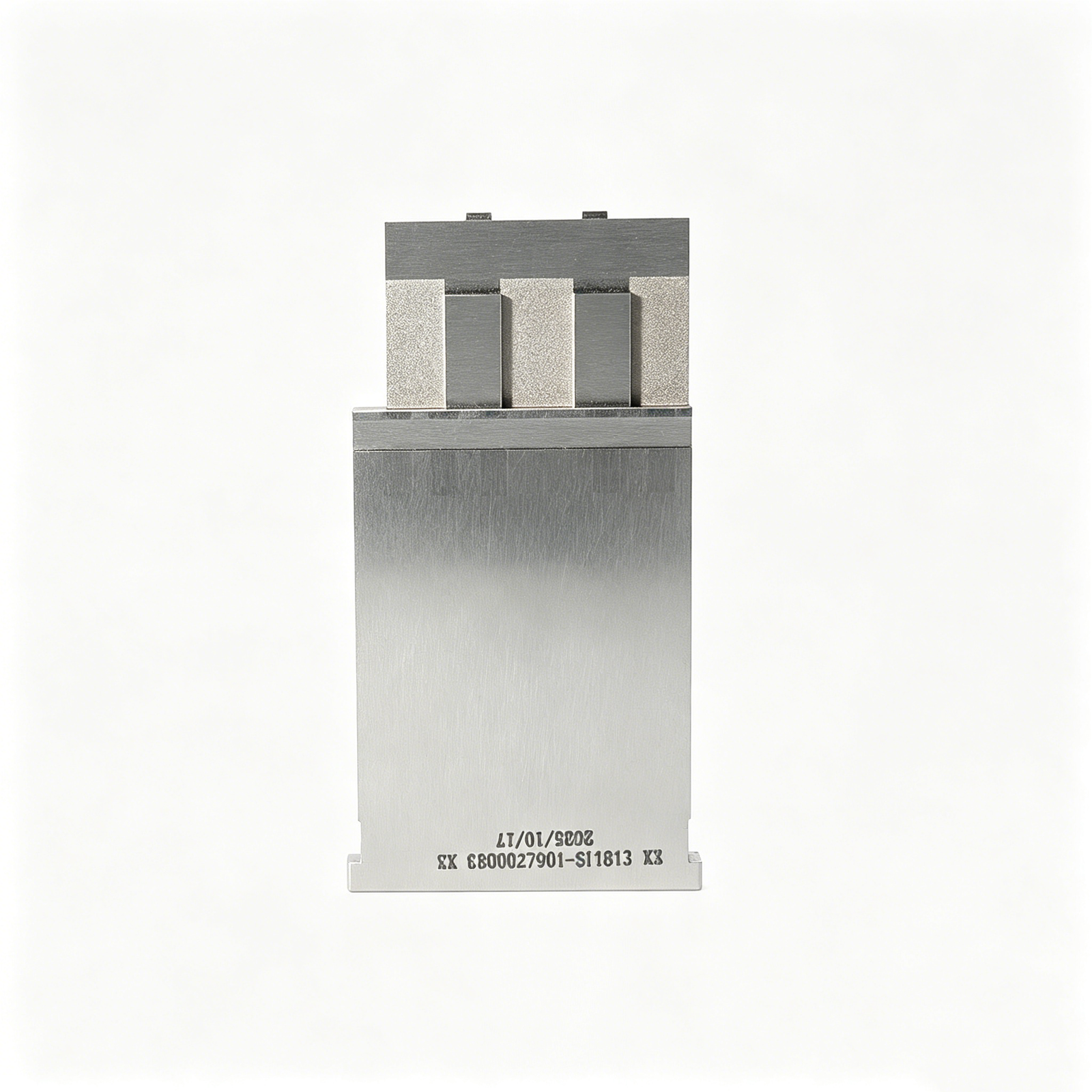
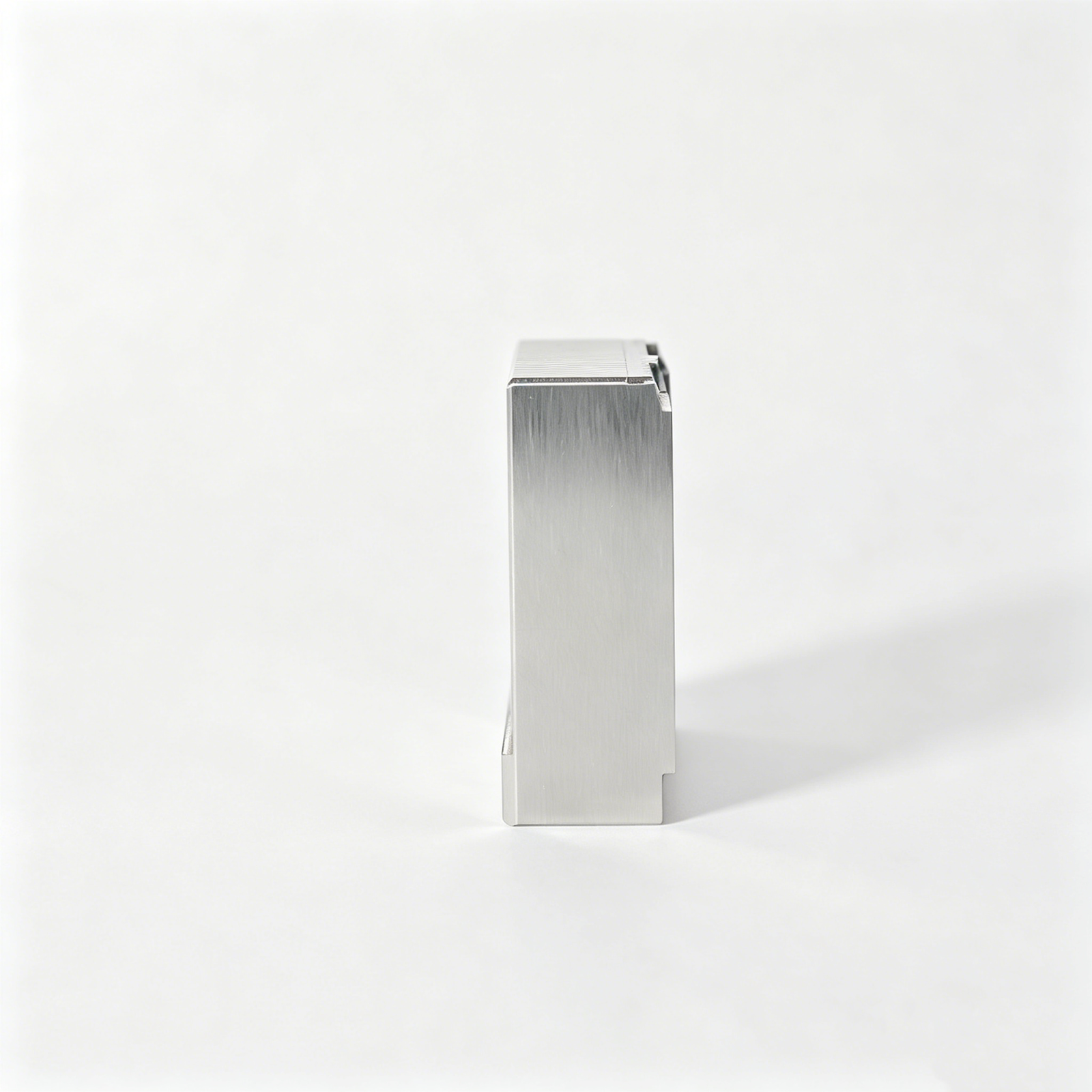
Representative Mold Date Insert Components




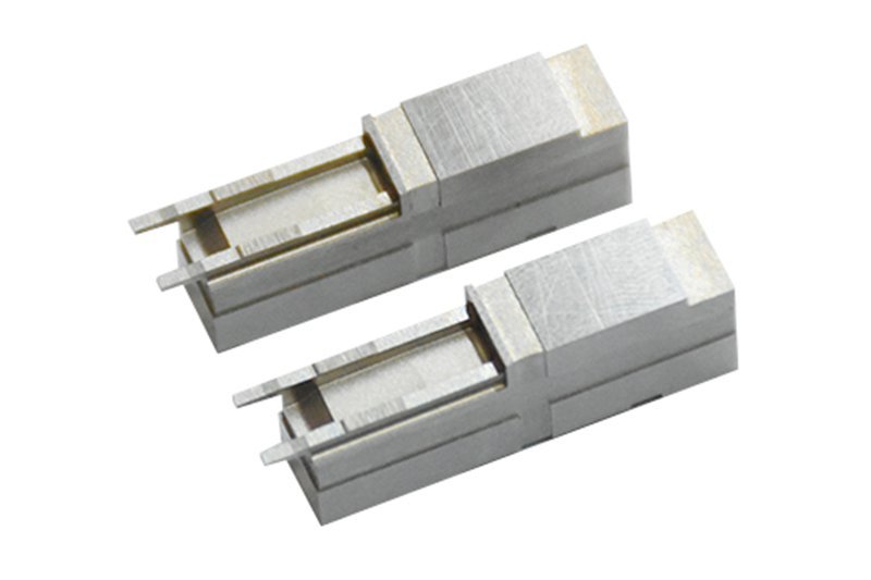


Related Drawing-Based Components







Mold Date Inserts, Reviewed for Production
Drawing-led decisions for custom insert projects before quotation and manufacturing commitments.
Drawing Comprehension
We review drawings and models for marking intent, installation context, dimensions, and manufacturing constraints before defining a workable production route.
Critical Dimension Review
Datums, fits, engraved features, and critical dimensions are identified early to align tolerance priorities with practical machining and inspection methods.
Coordinated Process Planning
CNC machining, EDM, grinding, and fitting are sequenced around material condition, access, electrode needs, and required finishing allowances.
Inspection Planning
Inspection requirements are discussed with drawing details, measurement priorities, and reporting expectations so evidence matches the agreed order requirements.
Revision Control
Controlled drawing revisions and visible project communication help prevent obsolete requirements from moving into machining, inspection, or delivery coordination.
Traceable Communication
Material, quantity, quality needs, delivery targets, and application context remain connected to the project discussion for clearer sourcing decisions.
Mold Date Inserts and Related Components
Classify drawing-driven component families, process routes and verification needs before requesting a quotation for date-marking, mold or tooling work.

CNC Machining Services
Precision CNC machining services for drawing-based inserts, date-marking housings and supporting mold components. Process planning considers material, datums, critical dimensions, access, heat-treatment sequence and inspection requirements before production commitments are made.
Upload a Drawing
CNC Milling
Custom CNC milling services for prismatic mold inserts, date-code pockets, mounting faces and feature-rich components. Drawing review should define datum references, cutter access, corner conditions, surface requirements and any grinding or EDM allowance.
Upload a Drawing
CNC Turning
Precision CNC turning services for round date inserts, bushings, sleeves, pins and cylindrical locating features. Quotations should identify concentricity, runout, thread details, engagement geometry, material condition and inspection methods tied to functional dimensions.
Upload a Drawing
5-Axis Machining
5-axis CNC machining supports complex insert geometry, angled features and multi-face work where repositioning may increase datum-transfer risk. Feasibility depends on tool reach, clamping strategy, internal geometry, required finish and the specified inspection approach.
Upload a Drawing
Swiss & Micro Machining
Swiss machining and micro machining support small-diameter pins, miniature sleeves, connector features and detailed cylindrical components. Buyers should provide diameter tolerances, length-to-diameter relationships, material, edge conditions, surface requirements and mating-component context.
Upload a Drawing
Wire & Sinker EDM
Wire EDM and sinker EDM services address sharp internal profiles, hardened materials, narrow slots, deep ribs and detail beyond practical cutter access. Electrode strategy, wire path, corner conditions, recast-layer expectations and finishing allowance should be reviewed from the drawing.
Upload a Drawing
Precision Grinding
Precision surface and profile grinding establishes controlled flatness, parallelism, profile and final-size conditions on mold and die components. The process plan should account for heat-treatment distortion, grinding stock, datum sequence, surface specification and verification method.
Upload a Drawing
Mold Core & Cavity Inserts
Precision mold core and cavity inserts are configurable drawing-based components for molding surfaces, shutoffs, details and replaceable wear areas. Review focuses on steel selection, parting relationships, cavity geometry, cooling interfaces, EDM needs and critical inspection points.
Upload a Drawing
Ejector & Ejection Components
Ejector pins, sleeves and ejection components are produced to drawing-defined dimensions for controlled movement within the mold. Functional review should cover clearance, guiding length, head or retention geometry, hardness requirements, lubrication conditions and wear-sensitive interfaces.
Upload a Drawing
Core Pins, Guide & Locating Components
Core pins, guide pins and locating components support repeatable alignment, molded detail and controlled assembly relationships. Supply drawings should identify working fits, datum references, mating components, straightness or concentricity needs, heat treatment and surface requirements.
Upload a Drawing
Slides, Lifters, Gates & Mold Accessories
Mold slides, lifters, gates and accessories cover configurable moving and supporting components used to manage undercuts, flow paths, alignment and mold operation. Evaluation includes travel geometry, interference risk, contact surfaces, wear conditions and assembly interfaces.
Upload a Drawing
Connector Mold Components
Precision connector mold components support high-density connector features, terminal-related tooling details and tightly controlled mating geometry. Manufacturing review considers micro-feature access, pin layout, material and hardness requirements, EDM or grinding needs, and inspection of critical pitch and profile dimensions.
Upload a Drawing
Stamping Die Components
Precision stamping die components include punches, dies, guide elements, inserts and custom wear parts made to drawing requirements. Process selection depends on profile complexity, clearance relationships, tool-steel condition, heat treatment, grinding stock and measurement needs.
Upload a Drawing
Injection, MIM, CIM & Overmolding Tooling
Injection, MIM, CIM and overmolding tooling components are evaluated as drawing-driven manufacturing work within verified production scope. Discussions should define molding material, cavity detail, shutoff conditions, inserts, tool access, wear expectations and quality documentation requirements.
Upload a Drawing
Machining Materials
CNC machining materials are selected against drawing requirements for strength, corrosion resistance, machinability, stability, heat treatment and application environment. Buyers should specify material grade, condition, approved equivalents and any traceability or certification requirements before quotation.
Upload a Drawing
Surface Finishes & Heat Treatment
Surface finishing and heat treatment are planned around functional surfaces, wear, corrosion resistance, friction and dimensional stability. Requirements should state the specified process, affected areas, masking needs, post-treatment dimensions, appearance criteria and any verification evidence required.
Upload a Drawing
Quality, Metrology & Documentation
Precision inspection, metrology and quality documentation are aligned with the order’s critical dimensions and approved inspection plan. Requirements may include dimensional reports, material records, process evidence, revision identification and traceable delivery documentation where specified.
Upload a Drawing
Prototyping & Low-Volume Production
Rapid prototyping and low-volume manufacturing support drawing-based evaluation, bridge needs and controlled production quantities. An effective RFQ identifies quantity, material, critical dimensions, surface priorities, revision status, required inspection and target delivery date.
Upload a DrawingSupported Materials for Mold Date Inserts

SUS420 Stainless
A martensitic stainless option often considered for date-marking inserts where corrosion resistance and heat treatment matter. Final grade, hardness condition, engraving detail, and mating fit are confirmed through drawing review before quotation.

S136 Stainless Steel
A corrosion-resistant mold steel considered for applications involving demanding resin or moisture exposure. Selection depends on the required surface condition, heat-treatment route, marking geometry, and the project’s verified material specification.

H13 Tool Steel
A hot-work tool steel option evaluated for inserts requiring toughness and thermal-service considerations. SUUXIANG reviews heat treatment, EDM or grinding allowance, engraving depth, and critical dimensions before confirming the process route.

1.2316 Tool Steel
A corrosion-resistant tool-steel grade considered for mold components where surface durability and environmental exposure affect material choice. Quoted compatibility depends on the approved drawing, target hardness, machining access, and inspection plan.

1.2344 Tool Steel
A tool-steel option reviewed for wear and heat-related demands in mold-component applications. Material acceptance is tied to supplied specifications, required heat treatment, dimensional priorities, and the planned CNC, EDM, grinding, and inspection sequence.
Manufacturing Processes for Mold Date Inserts

CNC Milling
CNC milling establishes flats, pockets, alignment features and external geometry where cutter access permits. Tool selection, datum setup and finishing allowance are reviewed to protect functional surfaces before downstream EDM or grinding.


Wire EDM
Wire EDM forms through profiles, fine slots and intricate contours that conventional cutters cannot access reliably. Wire path, start-hole location, corner conditions and required finish are reviewed against the drawing’s functional geometry.

Sinker EDM
Sinker EDM creates recessed characters, blind cavities and detailed marking geometry using an electrode matched to the required form. Electrode strategy, burn allowance and surface requirements are coordinated with the component’s mating features.

Precision Grinding
Precision grinding controls critical diameters, faces and datum surfaces after machining or heat treatment when the drawing requires a refined finish. Grinding stock, wheel access and inspection references are defined before final sizing.

Fitting Inspection
Fitting and inspection verify functional assembly relationships, critical dimensions and marking orientation against the agreed drawing revision. Inspection methods and reporting needs are aligned with the order so final documentation matches the inspection plan.
Mold Date Inserts: Supported Component Features

Locating Features
Locating flats, keys, shoulders or anti-rotation details can be machined where the component drawing and mold layout require controlled orientation during installation and adjustment.

Mounting Threads
Threaded bodies, retaining screws and service-access details can be considered for mold date inserts when the specified engagement, installation direction and surrounding plate geometry allow reliable machining.

Date Marking
Date wheels, month and year indicators, resin codes or customer identification marks can be produced from approved artwork, character requirements and readable marking-depth specifications.

Retaining Details
Retaining rings, detents, set-screw provisions or captured elements may be evaluated to support serviceability and repeatable indexing, subject to material, heat treatment and assembly requirements.

Custom Labels
Part numbers, revision identifiers and orientation marks can be added where they improve traceability during tooling assembly, inspection and maintenance without interfering with the molded-part marking surface.
About SUUXIANG Mold Date Inserts
Established in 2010 and based at Sanhe Industrial Park in Chang’an Town, Dongguan, Guangdong, China, SUUXIANG is the sole public-facing precision-manufacturing brand of Dongguan SuuXiang Precision Mold Co., Ltd., founded and legally represented by XiaoCheng Huang. We help international engineering, sourcing, and quality teams convert drawings and specifications into inspected mold date inserts, precision mold components, connector tooling, and custom CNC-machined parts.
Our work begins with drawing review and DFM: critical dimensions, datums, material and heat-treatment requirements, tool access, EDM or grinding strategy, and inspection expectations are clarified before production commitments. Integrated CNC machining, EDM, grinding, fitting, and inspection support a controlled route from revision-managed requirements to documented delivery.

Mold Date Inserts: Capability Review in Detail
DFM and Datum Review
Before quotation, SUUXIANG reviews mold date inserts against the drawing, model, molding surface, datum scheme, marking orientation, and installation access. The review identifies critical dimensions and production risks that must be resolved before process commitments are made.
- Confirm cavity or core location and marking-face orientation
- Define functional datums and critical-to-quality dimensions
- Check assembly clearance, access direction, and anti-rotation requirements
- Record drawing revisions and unresolved DFM questions

CNC and EDM Strategy
The machining route is selected from geometry, material condition, tolerance requirements, and tool access. CNC machining may establish primary forms, while wire EDM or sinker EDM can address restricted profiles, fine features, or internal geometry where a conventional cutter cannot reach reliably.
- Assess cutter reach, corner conditions, and feature depth
- Plan wire paths or electrode geometry where required
- Sequence machining around heat treatment and finishing needs
- Review EDM surfaces against functional and cosmetic requirements

Grinding and Fitting Allowance
Precision mold date inserts often depend on controlled stock for final grinding and fitting rather than dimensions taken directly from an early machining operation. SUUXIANG reviews mating conditions, lead-in features, and the allowance needed to finish functional surfaces without compromising datum control.
- Set stock allowance for grinding-critical surfaces
- Review mating bores, seats, and retention features
- Control transitions between machined and finished faces
- Align fitting requirements with the mold assembly context

Inspection Plan and Traceability
Inspection planning begins with the drawing’s functional requirements, not a generic checklist. SUUXIANG aligns measurement methods, reporting needs, and revision identification with the order so buyers can specify which dimensions, surface conditions, or documentation require formal verification before shipment.
- Identify dimensions requiring documented inspection
- Match measurement method to geometry and tolerance
- Confirm material, heat-treatment, and reporting requirements
- Maintain visible revision and delivery coordination

Why Choose SUUXIANG for Mold Date Inserts
Compare drawing review, process planning, revision control, and inspection alignment before production commitment.
← Swipe left or right to view →
Mold Date Inserts Production Workflow
A controlled path from technical review through documented inspection and delivery coordination.
Review Drawings and Requirements
We review 2D drawings, 3D models, material, quantity, date-marking requirements, critical dimensions, surface priorities, inspection needs, and target delivery expectations before quotation.
Confirm DFM and Process Route
The team evaluates datums, mold-location interfaces, machining access, press-fit requirements, electrode strategy, wire paths, grinding allowance, heat-treatment sequence, and revision status.
Plan Controlled Production
Approved requirements are translated into a manufacturing route combining CNC machining, turning where applicable, EDM, precision grinding, fitting, and in-process dimensional checks.
Machine Critical Insert Features
Mold date inserts are produced to the confirmed drawing, with attention to marking geometry, fit interfaces, functional alignment features, and protected critical surfaces.
Inspect, Pack, and Coordinate Delivery
Final inspection follows the agreed plan, documentation is matched to the order, and packing and delivery coordination remain aligned with the confirmed revision.
Work With SUUXIANG on Mold Date Inserts
Move from drawing review to controlled production with the specifications and quality evidence your project requires.
Submit Your Drawing Package
Provide the 2D drawing, available 3D model, material, quantity, application context, critical dimensions, surface requirements, inspection needs, and target delivery date.
Review DFM Requirements
Align on datums, tolerance stack, machining access, engraving details, heat-treatment sequence, EDM or grinding needs, and any mating-component constraints before quotation.
Confirm the Quotation
Review the proposed process route, commercial scope, revision status, quality expectations, and delivery assumptions so production commitments match the approved drawing package.
Approve Samples When Required
Evaluate first-off or sample parts against the agreed inspection plan, then resolve dimensional or documentation feedback before progressing to the next production stage.
Release Controlled Production
SUUXIANG coordinates machining, EDM, grinding, fitting, inspection, and delivery updates while maintaining revision visibility and documentation aligned with the verified order requirements.
Mold Date Inserts: Documentation Before Certification Claims
Customer Feedback on Mold Date Inserts
Customer references are published only after the customer approves attribution and the project evidence.
Approved case evidence may document drawing review, manufacturing, and inspection outcomes for comparable projects.
Published customer statements must match the delivered project and approved attribution.
Mold Date Inserts FAQ for Engineering Buyers
Practical guidance for preparing a drawing-led inquiry, reviewing manufacturability, and defining inspection and delivery requirements.
What information should I send for a mold date inserts RFQ?
Is there a minimum order quantity for custom mold date inserts?
Can you review my mold date inserts drawing before quotation?
How long do custom mold date inserts take to make?
Can I request first-article or dimensional inspection reports?
Do you ship mold date inserts internationally?
How are payment terms confirmed for custom precision parts?
How do you protect drawings and control design revisions?
The Complete Buyer’s Guide to mold date inserts
Use this decision framework to specify mold date inserts, compare compatible designs and materials, evaluate drawing-based suppliers, and avoid installation, traceability, tolerance, and lifecycle-cost mistakes before tooling release.
1. What Are mold date inserts?
A cavity-side marking component, a mold date insert forms permanent molded information such as a production date, batch code, resin identifier, recycling symbol, or part identifier. Its raised or recessed marks are reproduced on the part during molding, creating a direct link between the physical part and manufacturing records.
To prevent specification errors, define the installed marking assembly, its fixed body or retention feature, and any rotatable or replaceable core, ring, arrow, or character carrier. State the required legend, viewing orientation, cavity location, and whether the indexing element must be serviceable in the drawing or RFQ.
2. How mold date inserts Evolved
Fixed engraved date marks require replacement of the complete insert when the marking changes, while interchangeable cores separate the durable holder from the variable information. Verify mating dimensions and orientation against the approved drawing.
Indexable and front-removable designs can reduce maintenance interruption by allowing an operator to reset a rotating indicator or service an insert without disassembling a restricted mold area. The design still needs a defined locking feature, tool access, and anti-rotation datum.
Blind-hole inserts can suit restricted rear access, while multi-ring designs can combine date fields with identifiers such as resin, cavity, or recycling information. Specify the operating environment, marking-legibility requirement, and service method before selecting the configuration.
3. Types of mold date inserts
Mold date insert architecture should follow cavity access, required marking changes, and maintenance access. Specify the insert family on the mold drawing rather than assuming interchangeable supplier standards.
| Type | Marking And Adjustment | Installation Constraint | Maintenance And Best Fit |
|---|---|---|---|
| Integral/fixed | Permanent date; replace whole insert | Rear removal path required | Lowest complexity; stable programs |
| Replaceable-core | Changeable inner year or date | Body pocket must match core system | Renew core; planned annual updates |
| Indexable | Rotating month or batch indicator | Tool access for indexing required | Frequent changes; controlled traceability |
| Front-removable | Date or code insert changed from cavity face | Front tool clearance required | Service without rear access |
| Blind-hole/high-temperature | Date or identifier marking | No through-hole; confirm heat and cooling layout | Restricted cavities or thermal duty |
| Dual-ring/identifier | Separate date plus code fields | Larger pocket and readable mark area | Multi-cavity, resin, or customer traceability |
Fixed And Replaceable Cores

Fixed inserts suit stable annual markings and unrestricted rear access. Replaceable cores suit programs needing year-ring renewal without replacing the outer body.
Indexing And Front Access
Indexable inserts suit frequent month or batch changes when the marking must rotate in place. Front-removable designs suit cavity layouts where rear knockout access is unavailable.
Restricted Access And Identification

Blind-hole or high-temperature configurations suit blocked rear access, cooling constraints, or elevated thermal exposure. Dual-ring and identifier versions add separate date and part, resin, cavity, or customer-code fields.
4. Materials, Hardness, and Surface Protection
Material selection begins with the resin, cavity environment, cleaning practice, and intended service life. For mold date inserts, the chosen route must preserve mark geometry through repeated indexing and molding exposure.
| Approach | Primary Advantage | Review Point |
|---|---|---|
| Stainless | Corrosion resistance | Engraving and polish requirements |
| Tool steel | Wear resistance | Protection and heat-treatment sequence |
| Surface treatment | Environmental defense | Dimensional change and mark clarity |
Stainless Versus Tool Steel
Stainless approaches suit humid storage, corrosive resin by-products, or water exposure where rust can impair marks.
Tool-steel approaches can prioritize wear resistance and stable bearing surfaces when the environment and protection plan are controlled.
Heat Treatment Strategy
Heat treatment must follow the selected material and drawing requirements; hardness alone does not establish suitability.
Grinding stock, distortion risk, and final engraving sequence should be agreed before hardening so characters remain sharp.
Surface Condition And Indexing
Fine surface condition supports legible molded marks, while burrs or corrosion can damage mating bores and indexing features.
Datum-controlled diameters, flats, detents, and rotation interfaces require inspection against the approved drawing.
5. Marking and Customization Options
Two marking decisions govern both molded-part traceability and tool build: what the cavity forms, and how operators index it. Freeze readable content before detail design, not after steel is cut.
| Marking | Best Configuration | Freeze In |
|---|---|---|
| Month, year, day | Indexable ring or replaceable characters | Part and mold drawings |
| Shift, cavity, recycling, resin | Fixed engraving or dedicated ring | Part drawing and inspection plan |
| Logo, custom text | Drawing-based engraving | Artwork, orientation, inspection plan |
Select Traceability Content
Nine common fields are month, year, day, shift, cavity, recycling, resin, logo, and custom text.
One drawing note should define character case, language, symbol artwork, and the intended reading direction on the molded part.
Define The Marking Geometry

0.2 mm is a useful starting discussion point for shallow formed characters, but depth must suit resin flow, texture, polishing, and cleaning.
360° ring layouts require a defined index arrow, viewing side, zero position, and clockwise or counterclockwise convention.
Choose Fixed Or Replaceable Characters
Two routes are typical: catalog bodies with standard rings, or drawing-based inserts with custom diameter, layout, logo, and text.
Three records must agree before manufacture: part drawing for formed appearance, mold drawing for orientation and retention, and inspection plan for legibility verification.
6. Critical mold date inserts Quality Elements
Two functional interfaces govern a date insert: its cavity-seat relationship and its readable molded mark. Define both from the mold datum scheme, not nominal catalog dimensions.
Interface And Concentricity
Define bore, locating shoulder, runout, and concentricity only where the molded mark requires them; a tight tolerance should follow functional need and a verified measurement method.
Incoming inspection for critical fits should use the stated datums, suitable calibrated gauges, and a recorded actual-value report where required by the inspection plan.
Indexing And Retention
For multi-position indexing, define the index convention, detent engagement criterion, rotation-torque range, anti-rotation feature, and retaining-thread specification.
Sample checks should confirm repeatable indexing, no unintended rotation during molding, and service access with the specified tool. Record the test method and revision.
Mark Face And Durability
Visual review should verify mark alignment, engraving legibility, parting-surface flushness, and absence of burrs that can imprint flash or damage the cavity.
A controlled sample molding trial, when required, can verify actual molded character definition. State material, heat-treatment condition, corrosion-protection requirement, inspection method, and approval-controlled change process on the drawing.
7. Selecting a Drawing-Based Manufacturer
Two files—a controlled 2D drawing and matching 3D model—give a manufacturer the baseline for datum interpretation, engraving orientation, and revision control. A drawing-based supplier should respond with DFM questions, not merely a catalog match.
Request Evidence Before Award
Six RFQ inputs reduce ambiguity: drawing, model, material, heat treatment, quantity, and inspection expectations. Add the mating surface, marking artwork, target date, and required report format.
- Controlled drawing revision
- Material and heat-treatment evidence
- First-article inspection plan
Test Technical Response
Three review topics expose real engineering depth: datum scheme, engraving legibility, and machining or EDM access. Ask the supplier to identify risks, proposed allowances, and dimensions needing measurement methods before release.
Verify Production Discipline
Two evidence trails matter after quotation: traceable material and heat-treatment records, plus inspection results tied to the ordered revision. Confirm prototype handling, milestone communication, realistic lead-time assumptions, and a documented corrective-action response when results miss requirements.
8. Common Buyer Mistakes to Avoid
A date insert becomes a production risk when its drawing defines only what is visible on the molded part. Review the interface, service method, marking intent, and replacement path before cavity steel is released.
Define The Full Interface
A 6 mm nominal diameter alone does not define the seat, retention feature, depth, or tolerance. Ask: which mating dimensions and datum control interchangeability?
DME-, HASCO-, and CUMSA-style components are not automatically interchangeable. Ask: which manufacturer standard and exact drawing revision governs every mating feature?
Protect Access And Cavity Steel
A blind installation may require front removal, a rear knockout path, or a dedicated threaded extraction method. Ask: how will an operator remove the insert without damaging the cavity?
A cooling channel or thin cavity wall can limit insert location and serviceability. Ask: what minimum steel section and cooling clearance remain after machining?
Specify Readable Marking
A small mark can become illegible through texture, poor orientation, resin flow, or wear. Ask: can the molded mark be read from the required inspection view and at the intended surface finish?
A 0° orientation reference prevents month arrows, logos, and date rings from indexing inconsistently. Ask: what datum or witness feature defines the final molded-mark orientation?
Plan Material And Spares
A date insert without material, hardness, and corrosion expectations leaves the manufacturing route undefined. Ask: what material condition and heat-treatment evidence are required for the application?
A replacement insert is useful only when its drawing, revision, and fit are controlled before the first build. Ask: which spare quantity, identification, and inspection records must accompany production release?
9. From RFQ to Production Release
Two controlled releases prevent a date insert from becoming an untraceable mold change. Start the RFQ with the required date format, identification purpose, target resin, and reportable critical dimensions.
Assign Launch Ownership
Five functions should sign defined decisions: design owns mark content; tooling owns cavity interface; quality owns acceptance; procurement owns order data; program management owns timing and revision status.
Freeze Drawings And Installation
Three drawing sets are required: the insert detail, cavity detail, and mold-assembly interface. Confirm readable marking orientation, datum references, retention method, access for indexing or replacement, and any interference with cooling or ejector hardware.
Approve First Article Evidence
One pre-production sample should be reviewed against the released drawing and inspection plan before production release. Record marking legibility, installed position, functional rotation or replacement, dimensional results, lot identification, spare-part quantity, and revision-control rules.
10. mold date inserts Pricing and Cost
A defensible quotation separates the base insert, configuration-specific machining, and verification. Request an RFQ against the controlled drawing rather than relying on a catalogue comparison, because standard-family compatibility and marking layout can change the route.
Consider lifecycle questions alongside unit price: how quickly can a worn core be changed, and what is the impact of an unplanned mold stop? Include engraving, material, heat treatment, inspection evidence, nonstandard geometry, and replacement-core strategy in the comparison.
| Quantity tier | Configuration complexity | Customization level | Indicative lead-time band |
|---|---|---|---|
| 1–10 | Standard body, fixed marking | None or existing layout | Drawing review plus production scheduling |
| 10–50 | Indexable or replaceable core | Date format or logo engraving | Allow machining and inspection planning |
| 50–200 | Multiple diameters or mating interfaces | Dedicated core set | Allow setup, engraving, and batch verification |
| 200+ | Nonstandard geometry or material route | Tooling or controlled replacement program | Confirm capacity, release, and delivery plan |
Upload Your Drawing for a Mold Date Insert Quote
Include material, quantity, critical dimensions, inspection requirements, and target delivery date so SUUXIANG can review manufacturability before quotation.