
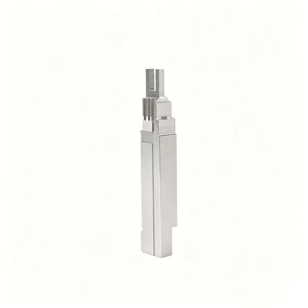
Drawing-Based Stepped Insert for Repeated Fine Features
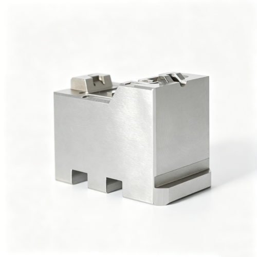
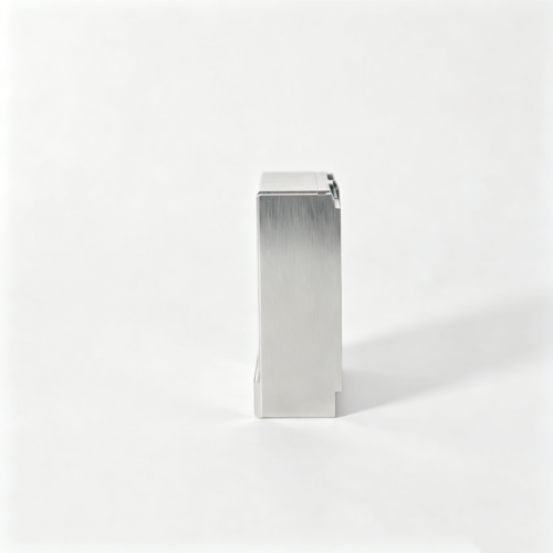
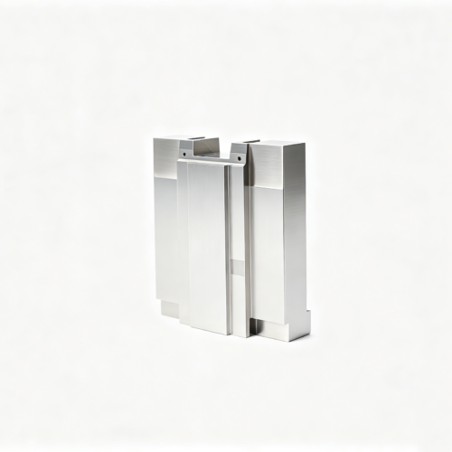
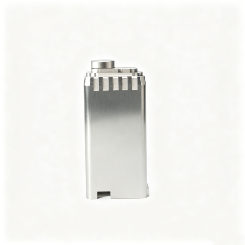
This custom stepped mold insert is intended for a drawing-led project involving a repeated fine-feature field, a shoulder, and mounting geometry that must remain related as one system. The product image is a distinct visual reference and does not define pitch, row count, material, heat treatment, tolerance, finish, application, or manufacturing history. The engineering decision is how to create and inspect the repeated details while preserving their position against the shoulder and assembly datums.
Fine-pitch insert planning with stable references, controlled pattern location, shoulder protection, and cumulative-position inspection.
Build the Pattern Definition
The RFQ package should include the latest controlled drawing, revision, units, three-dimensional data where available, quantity, material direction if known, thermal instructions if applicable, surface requirements, and inspection-document needs. The repeated field should be shown with its origin, pitch, orientation, reference edge, and relationship to the shoulder. Enlarged details should define fine-feature width, depth, corner condition, relief, and any edge break that affects assembly or release.
Relate Fine Features to the Shoulder
The main manufacturing challenge is often not an individual groove or tooth but the relationship between the complete field and the stepped shoulder. An individually square shoulder may still be misplaced relative to the pattern. Conversely, a visually even row may be correctly pitched but offset from the mounting datum. The process plan should therefore establish stable references before finishing the repeated details.
Depending on accessibility and feature scale, repeated details may be produced by suitable cutting, micro-machining, EDM, or a combined route. The selected method must account for tool access, burr formation, corner condition, debris removal, and the risk of pattern drift. A method that creates one feature accurately may still be unsuitable for controlling a long sequence. The drawing should identify whether the shoulder height, squareness, field depth, and pattern origin are functional.
Control Cumulative Position
Pattern position error can accumulate across a row. If each feature is placed from the previous feature, small deviations may shift the final feature even when local pitch checks appear acceptable. A process may instead benefit from a stable coordinate strategy, a defined pattern origin, or another approved method that controls both local spacing and overall field position. The correct choice depends on the drawing and the equipment available for the approved route.
Inspection should distinguish individual pitch from cumulative location. Check the first and last relevant features from the defined origin, measure representative intervals, and verify the complete field against the shoulder and mounting datums. If the drawing controls angular alignment or parallelism, include those relationships. Do not replace drawing-defined position with a visual judgment that the row appears regular.
Preserve the Stepped Geometry
The shoulder may need to remain protected while fine features are created. If assembly height is controlled, reserve stock at the shoulder only as needed and define when it will be removed. Excess stock can obstruct access or alter the final relationship; insufficient stock can leave no practical correction allowance. The sequence should also consider burr direction, tool approach, and the possibility that a finishing operation changes the shoulder edge.
Mounting references should be finished in a controlled order. A stable base, locating side, or other datum can support pattern creation and later inspection. If the shoulder is itself a datum, its height and squareness should be established before the repeated field is accepted. If it is only a clearance step, the drawing should say so. These distinctions affect both process priority and the final inspection report.
Account for Material Condition
No fixed material, hardness, coating, or heat treatment is assigned here. The approved customer drawing and engineering review govern those decisions. If thermal processing, stress relief, or another stabilization step is specified, the process should leave suitable stock and preserve reliable references for later correction. Fine features should not be finalized before a condition that could change their position or edge state.
Finish requirements should be attached to named surfaces. The repeated field, shoulder, base, and non-contact relief may need different finishes or different acceptance criteria. Grinding can alter shoulder height or edge condition; EDM can affect narrow corners; machining can leave burrs or directional marks. If thermal or surface changes are not specified, the quotation should state the assumption rather than silently assigning a standard.
Inspect Pitch, Shoulder, and Depth
A suitable inspection plan may combine optical measurement, magnified visual review, and datum-based dimensional checks. Optical measurement can evaluate repeated features without relying on contact force across delicate edges. Magnified review can identify burrs, chipped corners, overcut, taper, drag marks, or blocked relief. Datum-based checks should relate pattern position, shoulder height, squareness, and feature depth to the assembly references.
Record whether the insert is measured free-state, supported, or held in a defined fixture. Measure the drawing-defined pitch and also the relevant cumulative position across the field. Check the shoulder from the correct datum, not from a convenient but uncontrolled edge. If feature depth varies with tool access or finish direction, identify the inspection locations and acceptance logic before production release.
RFQ and Revision Discipline
For quotation, provide the controlled drawing, revision, model, quantity, units, material direction, any thermal instruction, surface requirements, and expected inspection documents. Mark the pattern origin, shoulder datums, mounting features, and critical edge conditions. Keep the original image as visual guidance only. If a later revision changes pitch, row extent, shoulder height, or feature depth, issue it as a controlled update and reassess the route.
Frequently Asked Questions
Can the image establish the exact pitch?
No. Pitch, field extent, and row count must come from the approved drawing.
Why measure cumulative position?
Small local errors can accumulate, leaving the final feature misplaced even when individual intervals look acceptable.
Can heat treatment be assumed?
No. Any thermal route must be specified or confirmed during engineering review because it may affect relationships and finish allowances.
Submit the Fine-Pitch Drawing
Share the controlled pattern and shoulder datums for process, fit, and inspection planning.
Reviews
There are no reviews yet.