
Fine Blanking Die Components for Drawing-Led OEM Manufacturing
DFM-led planning, precision machining, EDM, grinding, and inspection for fine blanking die components built to your drawing requirements.
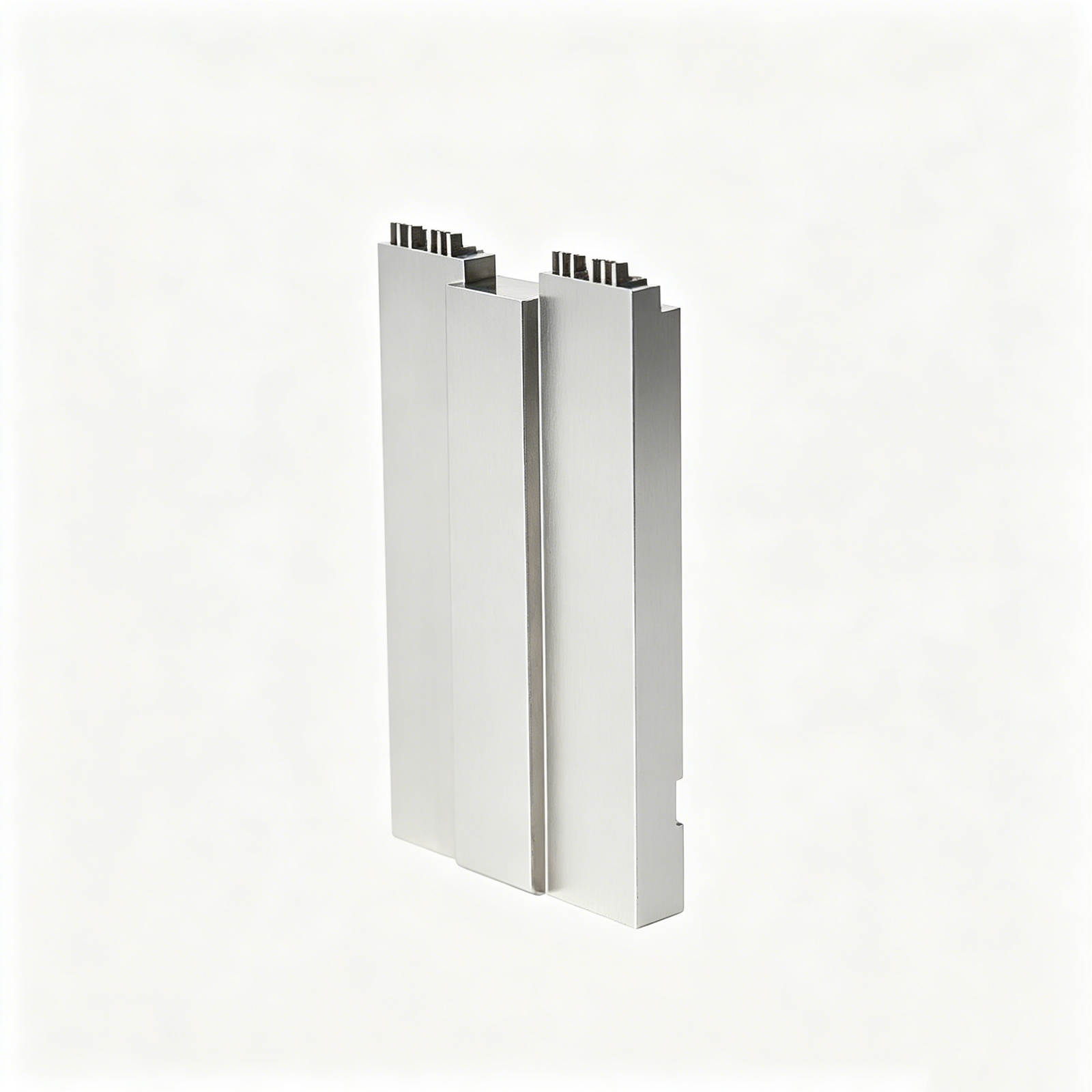
Representative Fine Blanking Die Components




Related Drawing-Based Components and Quotation






Why Engineers Source Fine Blanking Die Components Through SUUXIANG
Drawing-led planning keeps critical features, process choices, inspection expectations and revisions visible before production commitments.
Drawing Review First
Review drawings, models, datums, critical dimensions and application context before quoting so manufacturability questions are identified early.
Practical DFM Input
Discuss tool access, tolerance stack, machining allowance and heat-treatment sequence to help align component geometry with a workable route.
Coordinated Process Routes
Plan CNC machining, wire EDM, sinker EDM, grinding and fitting around the surfaces and features that control die performance.
Inspection Planning
Define critical dimensions, inspection methods and reporting expectations against the drawing, material requirements and agreed quality priorities.
Revision Visibility
Keep drawing revisions, manufacturing questions and delivery information visible throughout coordination, supporting traceable decisions from RFQ through inspection.
RFQ-Ready Communication
Submit material, quantity, surface priorities, target date and documentation needs with your drawing for a more focused project discussion.
Fine Blanking Die Components and Tooling Families
Discuss configurable, drawing-driven components and process routes before quotation, production planning, and inspection requirements are confirmed.

CNC Machining Services
Precision CNC machining services for drawing-based parts requiring planned milling, turning, EDM, grinding, fitting, and inspection. Share critical dimensions, material, quantity, surfaces, and delivery requirements so the process route can be reviewed before commitment.
Upload a Drawing
CNC Milling
Custom CNC milling services for plates, inserts, housings, profiles, pockets, and features requiring controlled tool access. Drawings should identify datums, critical dimensions, surface requirements, corner conditions, and any downstream EDM or grinding operations.
Upload a Drawing
CNC Turning
Precision CNC turning services for rotational parts such as pins, shafts, bushings, sleeves, and locating features. Review diameters, concentricity, runout, thread details, material condition, and how turned surfaces relate to mating or inspection datums.
Upload a Drawing
5-Axis Machining
5-axis CNC machining for complex geometry where multi-face access, angled features, or reduced setups affect accuracy and efficiency. Feasibility depends on part geometry, clamping strategy, tool reach, tolerances, material, and required inspection approach.
Upload a Drawing
Swiss & Micro Machining
Swiss machining and micro machining for small, slender, or detail-intensive components where support, concentricity, and feature access require careful planning. Provide dimensions, tolerances, material, quantity, and application context for a practical review.
Upload a Drawing
Wire & Sinker EDM
Wire EDM and sinker EDM services for hardened features, fine internal profiles, sharp corners, deep cavities, and geometry inaccessible to conventional cutting. Electrode design, wire path, recast-layer considerations, finish requirements, and subsequent fitting should be defined early.
Upload a Drawing
Precision Grinding
Precision surface and profile grinding for flatness, parallelism, profile control, and finish-critical surfaces on mold and die components. Grinding stock, heat-treatment sequence, datum surfaces, measurement method, and final tolerance requirements guide planning.
Upload a Drawing
Mold Core & Cavity Inserts
Precision mold core and cavity inserts made from customer drawings for injection-mold tooling applications. Discuss material, heat treatment, cavity geometry, cooling or venting features, EDM needs, shutoff areas, surface requirements, and dimensional inspection priorities.
Upload a Drawing
Ejector & Ejection Components
Ejector pins, sleeves, and ejection components configured for the mold’s ejection layout and operating conditions. Drawings should clarify fit relationships, sliding surfaces, hardness or finish requirements, stroke-related features, and interfaces with adjacent mold plates.
Upload a Drawing
Core Pins, Guide & Locating Components
Core pins, guide pins, and locating components for controlled alignment, feature formation, and repeatable assembly. Review geometry, working length, fit class, datum relationships, material and treatment requirements, and mating-component details before manufacture.
Upload a Drawing
Slides, Lifters, Gates & Mold Accessories
Mold slides, lifters, gates, and accessories for moving actions, part release, flow control, and supporting mold functions. Manufacturability depends on travel geometry, interfaces, wear surfaces, shutoffs, cooling needs, tolerances, and fitting expectations.
Upload a Drawing
Connector Mold Components
Precision connector mold components for fine-pitch, multi-cavity, and mating-feature tooling. Provide pin geometry, pitch requirements, datum scheme, material and hardness specifications, EDM or grinding needs, inspection priorities, and connector application context.
Upload a Drawing
Stamping Die Components
Precision stamping die components including punches, dies, inserts, guides, and wear parts produced to drawing-defined geometry. Process planning considers material, heat treatment, cutting edges, clearance relationships, profile accuracy, grinding stock, and inspection requirements.
Upload a Drawing
Injection, MIM, CIM & Overmolding Tooling
Injection, MIM, CIM, and overmolding tooling components within verified production scope. Discuss molded material, part geometry, cavity and core requirements, insert interfaces, shutoffs, venting, gating, expected wear, and quality criteria before the route is confirmed.
Upload a Drawing
Machining Materials
CNC machining materials selected from drawing and application requirements, including material grade, supply condition, hardness, corrosion resistance, and machinability. Material availability and certification needs should be specified with the RFQ rather than assumed.
Upload a Drawing
Surface Finishes & Heat Treatment
Surface finishing and heat treatment requirements planned around function, dimensional stability, wear, corrosion resistance, and mating surfaces. Specify finish type, roughness targets, coating or treatment standard, masking needs, post-treatment grinding, and inspection expectations.
Upload a Drawing
Quality, Metrology & Documentation
Precision inspection, metrology, and quality documentation aligned to the order’s critical dimensions and verified inspection plan. Identify report format, datum references, sampling or full inspection expectations, material records, revision level, and traceability needs at RFQ stage.
Upload a Drawing
Prototyping & Low-Volume Production
Rapid prototyping and low-volume manufacturing for drawing-driven parts, tooling components, and controlled design iterations. Provide the current revision, quantity range, material, critical features, intended validation use, inspection needs, and target delivery date for planning.
Upload a DrawingMaterials for Fine Blanking Die Components

Tool Steel
Selected for punches, die inserts, and wear-prone tooling where strength and heat-treatment response matter. Grade choice is reviewed against section geometry, required hardness, grinding stock, and expected production conditions.

High-Speed Steel
Considered for cutting elements requiring strong wear resistance and retained hardness. The drawing review should confirm edge geometry, EDM strategy, heat-treatment sequence, and whether subsequent grinding can establish critical cutting dimensions.

Carbide Grades
Evaluated for localized inserts and cutting areas exposed to demanding abrasive wear. Its high hardness requires careful machining and EDM planning, secure support design, and clear inspection criteria for brittle-edge risk.

Alloy Tool Steel
Used where toughness, through-hardening behavior, and machinability must be balanced for structural die components. Material selection depends on load paths, dimensional stability after heat treatment, fitting requirements, and service environment.

Stainless Tool Steel
Considered when corrosion resistance is relevant alongside tooling performance. The project review compares hardness needs, machining access, finishing requirements, and the application environment before confirming a suitable material and process route.
Fine Blanking Die Components: Supported Precision Processes


Wire EDM
Wire EDM produces precise profiles, narrow slots and internal contours where conventional cutting access is limited. The wire path, start holes and finishing strategy are planned against critical geometry and mating requirements.

Sinker EDM
Sinker EDM forms detailed cavities, sharp internal features and difficult-to-reach tool geometry using purpose-planned electrodes. Electrode wear, finish expectations and subsequent polishing or fitting requirements should be defined during review.


Controlled Fitting
Component fitting evaluates how fine blanking die components locate, slide and mate within the tooling assembly. Clearance, contact condition and adjustment needs are handled against the approved drawing and revision information.

Inspection Planning
Inspection is planned around critical dimensions, datums, surface requirements and order-specific reporting needs. Results and documentation should align with the agreed inspection method, revision level and traceability expectations.
Fine Blanking Die Components: Accessories and Identification

Locating Features
Dowel holes, keys, shoulders, and locating pins help establish repeatable position between die elements. Define datums, fit requirements, mating parts, and assembly sequence so machining and inspection can be planned around functional alignment.

Retention Fasteners
Socket screws, retaining plates, and threaded features secure inserts, punches, and wear elements in the die assembly. Provide thread standard, head-clearance constraints, torque considerations, and service-access needs with the drawing for review.

Die Springs
Springs can support stripping, return, preload, or controlled movement in fine blanking tooling. Specify installation envelope, working travel, load requirement, and mating geometry so the accessory selection can be verified for the application.

Part Identification
Laser marking, engraved identifiers, revision codes, or controlled labels can help distinguish matched components and support traceability during assembly and maintenance. Marking location and legibility requirements should avoid critical surfaces or functional datums.

Protective Treatments
Corrosion-preventive oil, protective packaging, and drawing-specified surface treatments can be considered for storage, shipment, or operating conditions. Confirm material, heat treatment, surface requirement, and any mating or lubrication constraints before production.
About SUUXIANG Precision Manufacturing
SUUXIANG is the sole public-facing brand of Dongguan SuuXiang Precision Mold Co., Ltd., established in 2010 in Chang’an Town, Dongguan, Guangdong, China. Founded by XiaoCheng Huang, the company helps international engineering, sourcing, and quality teams turn drawings and specifications into inspected custom CNC parts, precision mold components, connector tooling, and fine blanking die components.
Our work brings CNC milling and turning, multi-axis machining, wire EDM, sinker EDM, precision grinding, fitting, and inspection into a controlled process plan. Before quotation and production, we review critical dimensions, datums, material and heat-treatment requirements, machining access, EDM needs, grinding allowance, and inspection expectations.
What distinguishes SUUXIANG is disciplined communication around manufacturability, revision control, and traceable quality evidence. We treat each component family as drawing-configurable rather than a presumed catalog item, aligning the process route and final documentation with the requirements verified for the specific order.

Fine Blanking Die Components Built Around Critical Details
DFM Before Commitments
SUUXIANG reviews the drawing, 3D model, material, quantity, and application context before defining a workable route for fine blanking die components. The discussion identifies critical dimensions, datums, tool access, heat-treatment sequence, and inspection expectations before production commitments.
- Clarify functional dimensions and tolerance stack
- Review datum strategy and mating features
- Identify machining access and EDM requirements
- Align material and heat-treatment information

Process Routes With Purpose
CNC milling, turning, multi-axis machining, wire EDM, sinker EDM, precision grinding, and fitting are planned as connected operations. Each route is selected around geometry, hardness condition, surface requirement, and the stock needed to protect critical features through later stages.
- Plan roughing and finishing allowances
- Use wire paths for narrow or enclosed profiles
- Define electrode strategy for internal geometry
- Reserve grinding stock for controlled finishes

Inspection Tied to Function
Inspection planning starts with the dimensions that control fit, position, movement, or sealing in the assembled die. SUUXIANG aligns measurement methods and reporting needs with the approved drawing so quality evidence addresses the features that matter to the application.
- Prioritize critical-to-quality dimensions
- Confirm measurement datums before inspection
- Match reporting scope to the order
- Record results against the current revision

Visible Revision Control
Drawing-based tooling work changes quickly when interfaces, tolerances, or materials are refined. SUUXIANG keeps revision, manufacturing, inspection, and delivery information coordinated so the team can verify what was built and what documentation should accompany the order.
- Confirm the released drawing revision
- Track approved changes through production
- Coordinate delivery against project requirements
- Keep inspection documentation order-specific

Fine Blanking Die Components: SUUXIANG vs. a Typical Job-Shop Quote
Compare the engineering evidence exchanged before production begins.
← Swipe left or right to view →
Fine Blanking Die Components: Drawing-to-Delivery Workflow
A drawing-led sequence that keeps DFM, process decisions, inspection requirements, and revision status visible from RFQ through shipment coordination.
Review RFQ Package
Send drawings, models, quantities, material requirements, target dates, and inspection expectations. SUUXIANG reviews revision status, critical dimensions, datums, and application context before quotation.
Confirm DFM Strategy
The team assesses machining access, tolerance stack, tool geometry, heat-treatment sequence, EDM requirements, grinding allowance, and measurable acceptance criteria before production commitments are confirmed.
Plan Material And Processes
Approved requirements are translated into a controlled route combining material preparation, CNC milling or turning, multi-axis work, wire EDM, sinker EDM, and intermediate checks as needed.
Machine, Grind, And Fit
Fine blanking die components move through the planned operations, with grinding stock, mating relationships, electrode strategy, and fitting needs managed against the released drawing revision.
Inspect, Pack, And Coordinate
Final inspection follows the agreed plan and order requirements. Parts are protected for shipment, with documentation, identification, and delivery coordination aligned to the confirmed project scope.
How to Source Fine Blanking Die Components
Move from a controlled drawing review to approved production with requirements, inspection expectations, and revisions clearly aligned.
Submit Your Drawing Package
Upload the 2D drawing and available 3D model, including application context, critical dimensions, datums, surface requirements, material, heat treatment, and target quantity.
Confirm Production Requirements
Review manufacturability, machining access, EDM or grinding needs, inspection expectations, revision status, delivery target, and any mating-component details that affect the process route.
Review Quote or Sample
Assess the proposed process plan, commercial scope, and quality documentation needs; where appropriate, use sampling to confirm critical features before production release.
Release Approved Production
Approve the final requirements and revision, then SUUXIANG coordinates machining, EDM, grinding, fitting, inspection, and delivery information against the verified order plan.
Fine Blanking Die Components: Documentation and Certification Evidence

The Complete Buyer’s Guide to Fine Blanking Die Components
Authorized customer feedback will be published only after project approval, with the applicable part scope, inspection outcome, delivery result, and measurable performance evidence confirmed for this fine blanking die components program.
This reserved case-study slot will document an approved drawing-to-inspection outcome, including the relevant critical dimensions, revision status, quantity, and any verified delivery or quality result for a completed tooling component project.
Customer comments are added only with authorization and verified project records. The final testimonial may describe DFM feedback, machining and EDM coordination, inspection documentation, or an approved corrective-action outcome.
Fine Blanking Die Components FAQ
Practical RFQ, quality, and delivery questions for drawing-led tooling-component projects.
What information should I send for a fine blanking die components quote?
What is the minimum order quantity for fine blanking die components?
Can you make prototype fine blanking die components before production?
How is lead time confirmed for custom die components?
Which tolerances should be highlighted on a fine blanking die component drawing?
Can SUUXIANG provide inspection reports with an order?
How are payment and shipping arranged for international orders?
How do you protect drawings and intellectual property?
The Complete Buyer’s Guide to fine blanking die components
Use this decision framework to specify fine blanking die components, evaluate supplier engineering and quality controls, compare tooling choices, and avoid costly DFM, material, tolerance, and validation mistakes before production.
1. What Are Fine Blanking Die Components?
Three controlled actions define fine blanking: the main punch cuts, the V-ring or blank holder clamps the sheet, and the counterpunch supports and ejects the workpiece. Fine blanking die components are the precision tooling elements that create and manage those forces around the cutting zone (https://www.principalmfg.com/what-is-fineblanking-technology).
A production part is the stamped sheet-metal item delivered to the customer; the die set is the complete assembled tool installed in the press. Replaceable wear components within that die set can include punches, die inserts, V-ring elements, guide parts, ejectors, and retainers.
Clearance, alignment, and fitted interfaces determine whether the material shears cleanly or develops fracture, burrs, distortion, and unstable dimensions. Controlled clamping and counterforce help preserve flatness, while repeatable guide location and serviceable wear parts protect tool life and make maintenance decisions traceable.
2. Evolution of Fine Blanking Tooling
1922 is commonly cited as the year Fritz Schiess-Forrer patented fine blanking; industrial adoption followed in 1959, with large-scale German production reported from 1964 (https://www.youtube.com/watch?v=oYlBcosclFU). Triple-action presses combined controlled punch force, V-ring clamping, and counterpressure to create flatter, more fully sheared edges than conventional blanking.
1960s–1980s tooling advances paired more robust press systems with higher-performance die steels, heat treatment, and precision grinding. These changes made clearance, punch-to-die alignment, and replaceable wear elements more controllable, supporting longer-running tools and reducing secondary deburring or machining where the part geometry permits.
1990s onward, wire EDM, sinker EDM, CAD/CAM, coatings, and in-process monitoring expanded contour complexity while making tool maintenance more deliberate. Current sourcing expectations should therefore include datum-based drawings, a documented clearance and grinding-stock strategy, insert and electrode access, planned inspection points, and revision-controlled spares—not a tolerance claim detached from material, press, and validation evidence.
3. Types of Fine Blanking Die Components
Six component families determine whether a fine-blanking tool cuts cleanly, stays aligned, and can be serviced predictably. Treat cutting interfaces as wear parts; retainers and die-set members are normally fixed assets.
| Family | Role | Common Failure | Buyer Must Communicate |
|---|---|---|---|
| Punches and die inserts | Shear contours | Chipping, edge wear | Material, thickness, critical profile |
| V-ring and clamp plates | Restrain stock | Ring wear, marking | Clamp force, surface limits |
| Guides and alignment | Maintain concentricity | Bushing wear, misalignment | Datums, press-side layout |
| Backing and retention | Support inserts | Fretting, loose retention | Seat geometry, service method |
| Counterpunch and ejectors | Apply counterpressure, release part | Galling, sticking | Flatness, ejection timing |
| Die-set structures | Carry tool loads | Plate distortion, fastener loosening | Press envelope, mounting details |
Wear Versus Fixed Parts
Cutting elements, V-rings, guide bushings, and ejector faces require planned wear review because contact loads and sliding can change their working geometry.
Fixed plates, shoes, backing blocks, and retainers should preserve datum relationships; cracking, fastener loosening, and distorted seating are their principal risks.
RFQ Information That Changes Design
2D drawings should identify functional datums, profile tolerances, material thickness, burr direction, and all critical contours. Supply strip layout, press direction, stroke rate, lubrication, and expected tool life where available.
3D models should show mating features and interference zones. SUUXIANG can review the specified inspection plan, revision level, and service-part expectation before proposing a process route.
4. Materials for Fine Blanking Die Components
Three variables—workpiece grade, sheet thickness, and planned stroke volume—set the starting point for material selection. Fine blanking die components need a hardness-toughness balance rather than a universally hardest alloy.
| Component | Primary Selection Priority | Typical Material Direction |
|---|---|---|
| Punch | Toughness and edge retention | Heat-treated tool steel; carbide conditionally |
| Die insert | Wear resistance and polishability | Tool steel or carbide by stock wear |
| Guide elements | Wear and fit stability | Hardened, ground steel |
| Backing plate | Load distribution | Tough steel |
| Structural plate | Stiffness and stability | Stable structural steel |
Match Cutting Members
Punches and die inserts typically use heat-treated tool steel when toughness and grindability must coexist.
Carbide becomes a candidate for abrasive stock or very high wear demand, provided backing and impact loading are controlled.
Specify Support Components
Guide pins and bushings need wear resistance, finish quality, and stable fit after heat treatment.
Backing plates spread cutting load; structural plates prioritize stiffness and dimensional stability over cutting-edge hardness.
Review The Full Process
Higher-strength or thicker strip raises edge loading, while production volume and lubricant condition change wear expectations.
Tolerance targets also determine grinding strategy, polishability, and whether a selected substrate can accept the required coating.
5. Custom Fine Blanking Die Components
Custom fine blanking die components should be specified from the drawing outward: functional geometry, mating interfaces, service conditions, and inspection evidence. SUUXIANG reviews the manufacturability of requested CNC, EDM, grinding, fitting, and inspection routes before machining begins.
Define Functional Dimensions
2D drawings should identify CTQ dimensions, geometric tolerances, datum references, surface requirements, and dimensions that may use general tolerances.
3D models should match the released drawing, while revision level, material, heat treatment, and quantity remain controlled in the RFQ.
- Separate cutting-edge, locating, and assembly dimensions from noncritical features.
- State datum A, B, and C before assigning positional tolerances.
- Flag mating-component interfaces and required inspection reports.
Engineer Working Surfaces

Clearance, edge condition, finish, and coating requirements must be defined by the die function and work material rather than copied from an unrelated tool.
Heat-treatment sequence and grinding stock affect final geometry; specify identification marks, orientation, and protected surfaces before release.
- Define punch-to-die clearance strategy.
- Specify coatings only with substrate and service intent.
- Locate marks away from sealing, cutting, and fitting faces.
Control Interchangeable Interfaces
Interchangeable inserts need controlled locating faces, fastening features, extraction access, and assembly datums. A DFM review should confirm tool access, wire paths, electrode strategy, grinding allowance, and measurable acceptance criteria before material is cut.
6. Construction Quality in Fine Blanking Die Components
Acceptance criteria for fine blanking die components should control the assembled tool, not isolated dimensions alone. Require the supplier to link every critical feature to a datum scheme, inspection method, and revision-controlled drawing.
Cutting Interface Control
Punch-to-die clearance, concentricity, and guide alignment should be specified against functional datums. Review V-ring geometry, cutting-edge finish, backing support, and insert retention together; any stack-up can alter burr formation and edge condition.
- Record clearance and concentricity requirements
- Define guide-fit inspection locations
- Specify burr acceptance limits
Ejection And Stack-Up
Ejector travel, return condition, and contact support require an assembly check before shipment. Confirm that retainers, backing plates, guide elements, and cutting inserts seat without unintended preload or movement.
- Verify ejection stroke and return
- Check seating faces and fasteners
- Document assembly-check results
Evidence For Acceptance
Dimensional reports should identify measured features, actual results, instruments, and drawing revision. Material traceability, hardness verification where specified, and final assembly records create a usable acceptance package for the buyer.
- Material certificate linked to part
- Hardness result linked to requirement
- Inspection report linked to revision
7. Choosing a Fine Blanking Die Components Supplier
Two suppliers can machine an acceptable first-off part yet differ sharply in production discipline. Evaluate fine blanking die components against the released drawing, process route, inspection evidence, and revision response.
| Evaluation Area | Ask In The RFQ | Evidence To Review |
|---|---|---|
| DFM and drawings | How are CTQs and datums interpreted? | Written review and assumptions |
| Machining and grinding | What route controls hardened features? | Process and inspection plan |
| Quality and changes | How are revisions and defects contained? | Revision log and reports |
| Delivery and packaging | What protects finished edges in transit? | Packing method and schedule |
Review Engineering Capability
One drawing review should identify datums, CTQ features, tool access, wire paths, EDM electrodes, grinding stock, and heat-treatment sequence.
Two RFQ questions matter: Which dimensions drive the process plan, and which drawing ambiguities require written disposition?
Verify Production Controls
Three linked controls—material and heat-treatment records, calibrated metrology, and order-matched inspection reports—support traceability.
One approved sample proves only that a result was achieved once; repeatability requires documented setup, in-process checks, packaging, and change control.
Plan The Program
Two delivery stages, prototype and production, should have separate lead-time assumptions, approval gates, and capacity discussions.
One accountable contact should confirm revision receipt, report format, shipment protection, and escalation timing before machining begins.
8. Common Fine Blanking Die Components Sourcing Mistakes
Before purchase-order release, fine blanking die components should be sourced against a controlled drawing package, not a quote line. Most avoidable failures begin when critical manufacturing decisions remain implicit.
Define Drawings And Datums
A 2D drawing without datums, section views, fit intent, or surface callouts invites different interpretations. The result is rework or components that measure acceptably yet fail to assemble.
Before release, identify functional datums, critical dimensions, mating interfaces, and acceptance criteria; provide the current 3D model and drawing revision.
Align Tolerances With Function
A unilateral or extremely tight tolerance applied without a functional reason can drive unnecessary EDM, grinding, and inspection effort. Conversely, broad limits on locating features create fit variation and inconsistent output.
Before release, assign tolerances by function, tolerance stack, process access, and inspection method—not by copying a default title-block value.
Specify Material And Serviceability
A tool-steel grade alone does not define hardness, heat-treatment sequence, finish, or wear behavior. Treating steels as interchangeable can cause premature wear, distortion, or difficult replacement.
Before release, define material condition, heat treatment, surface requirement, replaceable wear parts, and access for fitting or maintenance.
Control Cost, Inspection, And Changes
A lowest-piece-price decision can omit inspection evidence, revision discipline, and early DFM review; the apparent saving becomes schedule risk. Informal drawing changes also leave suppliers producing different configurations.
Before release, agree the inspection plan, report format, revision identifier, change-approval path, and DFM actions in writing.
9. From RFQ to Tool Validation
A controlled launch converts a drawing package into a validation plan before steel is cut. For fine blanking die components, each handoff should assign technical ownership, acceptance evidence, and revision authority.
Build The RFQ Package
Before quotation, the buyer supplies 2D drawings, 3D models, annual volume, strip or part function, material, heat treatment, CTQ dimensions, and target date.
During review, the component supplier identifies machining access, datum conflicts, EDM or grinding needs, and inspection risks; the die builder confirms interfaces and the production team supplies press and trial constraints.
- State mating-part and assembly context
- Mark critical dimensions and surfaces
- Name required reports and revision level
Freeze Assumptions Before Release
Before release, the quote must identify included material, heat-treatment sequence, finish, inspection scope, quantity, delivery basis, and excluded work.
After DFM closure, the buyer approves controlled drawings; SUUXIANG manufactures and inspects to that agreed plan, while the die builder verifies fit within the complete tool.
Validate, Correct, And Maintain
At first article or trial, the production team records run conditions and functional results, while the buyer compares parts against agreed acceptance criteria.
After a deviation, the responsible party documents root cause, correction, drawing impact, and revalidation. Before production release, define wear spares, maintenance intervals, storage, and revision-controlled replacement approval.
10. Fine Blanking Die Component Pricing
3 quote types require different logic: a complete die is priced as an engineered assembly, a replacement insert against its mating datums, and a prototype component against learning risk and limited-run setup.
9 cost drivers should be reviewed before comparing bids. SUUXIANG should price from the released drawing, material and heat-treatment specification, CTQ dimensions, revision level, quantity, and required inspection evidence—not from a generic price list.
1 RFQ should identify whether assembly fitting, rush delivery, or coating is included. A lower unit price can omit electrode work, grinding stock, inspection reporting, or revision-controlled fitting that the application actually needs.
| Cost driver | Typical cost impact | Buyer action |
|---|---|---|
| Complexity | Higher | Provide 3D model and datum scheme |
| Material grade | Variable | Name grade and condition |
| Heat treatment | Higher | State hardness and sequence |
| Coating | Higher | Specify type and functional area |
| Tolerance | Higher | Mark CTQ dimensions |
| Quantity | Lower per part at volume | State release schedule |
| Inspection documents | Higher | Define report and sampling needs |
| Assembly requirements | Higher | Provide mating-part data |
| Lead time | Higher when compressed | Give target delivery date |
Submit Fine Blanking Die Components Drawings for Review
Include material, heat treatment, quantity, critical dimensions, inspection requirements, and target delivery date for a project-specific manufacturing review and quote.