
Fine-Pitch Card Edge Connector Tooling, Reviewed Before Production
Submit your drawing for fine-pitch card edge connector tooling with DFM, critical-dimension review, process planning, and inspection requirements aligned before manufacture.
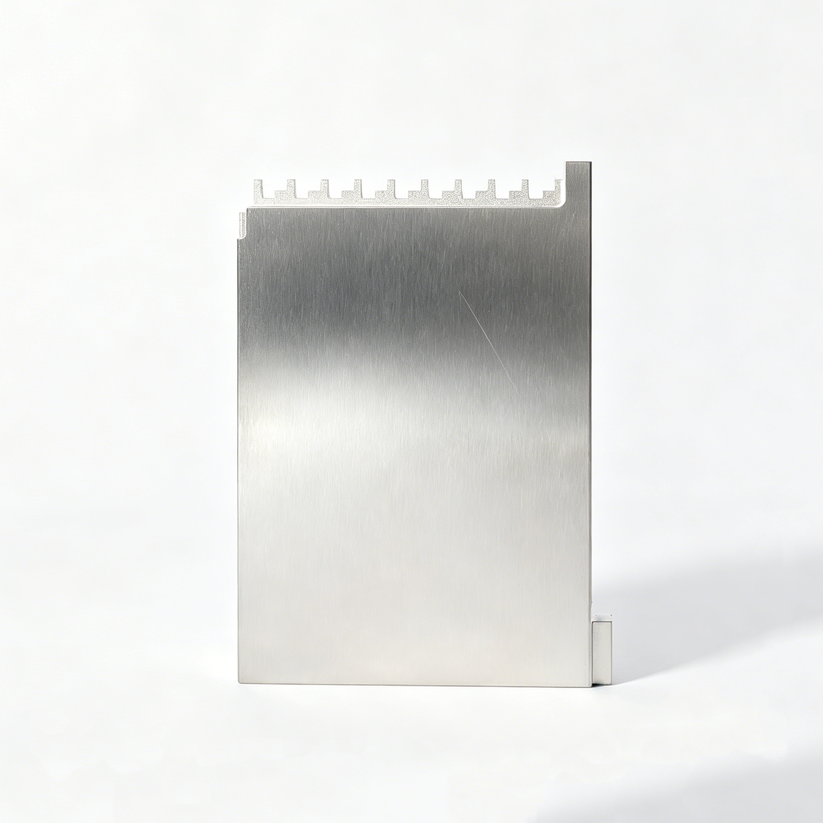
Representative Components for Fine-Pitch Card Edge Connector Tooling




Related Drawing-Based Component Families and RFQ Support








Fine-Pitch Card Edge Connector Tooling Engineering Advantages
Turn drawing requirements into a controlled manufacturing plan before production commitments are made.
Drawing-Led DFM Review
Review geometry, material, application context and critical requirements early to identify manufacturability questions before quotation and production planning.
Critical Dimension Strategy
Define datums, tolerance priorities and measurement methods around features that govern alignment, contact geometry and functional mating relationships.
Process Route Planning
Plan CNC machining, EDM, grinding and fitting in sequence, with allowances and access conditions evaluated against the drawing.
EDM and Grinding Decisions
Assess wire paths, electrode needs, corner conditions and grinding stock where fine connector-tooling features require controlled finishing.
Revision-Controlled Communication
Keep drawing revisions, open technical questions and agreed changes visible so production follows the current approved requirements.
Inspection Plan Alignment
Match inspection documentation and methods to agreed critical dimensions, surface priorities and reporting requirements for the specific order.
Fine-Pitch Connector and Die Component Families
Match drawing-driven connector mold and stamping-die requirements to the machining, EDM, grinding, inspection, and documentation route they require.

CNC Machining Services
Precision CNC machining services for drawing-based custom parts requiring coordinated milling, turning, EDM, grinding, fitting, and inspection. RFQ review identifies critical dimensions, datums, materials, heat treatment, surface requirements, quantities, and delivery priorities before a process route is proposed.
Upload a Drawing
CNC Milling
Custom CNC milling services for plates, inserts, blocks, pockets, slots, and formed details used in molds, connector tooling, and dies. Drawing review considers tool access, corner conditions, datum references, machining allowance, wall geometry, and subsequent EDM or grinding requirements.
Upload a Drawing
CNC Turning
Precision CNC turning services for rotational parts such as pins, sleeves, bushings, shafts, and locating elements. Requirements should define diameters, concentricity, runout, threads, surface condition, material state, heat treatment, and any secondary grinding or inspection needs.
Upload a Drawing
5-Axis Machining
5-axis CNC machining supports complex features that benefit from multi-angle tool access and fewer workholding changes. It is evaluated for contoured mold details, angled holes, connector-tooling features, and parts where datum control, reach, collision risk, and finishing access must be reviewed.
Upload a Drawing
Swiss & Micro Machining
Swiss machining and micro machining support small, detail-intensive turned components where geometry, handling, and measurement require careful planning. Suitable routes depend on part diameter, length-to-diameter relationship, material, feature size, tolerances, surface requirements, and inspection method.
Upload a Drawing
Wire & Sinker EDM
Wire EDM and sinker EDM services address hardened materials, narrow slots, sharp internal details, complex profiles, and features inaccessible to conventional cutting tools. The process review defines wire path or electrode strategy, corner conditions, EDM allowance, recast-layer considerations, and finishing requirements.
Upload a Drawing
Precision Grinding
Precision surface and profile grinding is used to establish controlled flatness, parallelism, profiles, and final size on mold and die components. Planning should account for heat-treatment condition, grinding stock, datum sequence, wheel access, surface requirements, and inspection criteria.
Upload a Drawing
Mold Core & Cavity Inserts
Precision mold core and cavity inserts are configurable components produced from approved drawings and process requirements. Review focuses on parting geometry, shutoff areas, cooling or vent features, material and hardness, EDM details, grinding allowance, critical dimensions, and fitting relationships.
Upload a Drawing
Ejector & Ejection Components
Ejector pins, sleeves, and ejection components are planned around motion, fit, wear, and mold-stack relationships. Provide drawing dimensions, material and heat-treatment requirements, surface needs, mating-component context, clearance expectations, and inspection priorities for an appropriate route.
Upload a Drawing
Core Pins, Guide & Locating Components
Core pins, guide pins, and locating components require controlled relationships to their mating bores, plates, and assemblies. Drawing review considers functional datums, fit class, straightness, concentricity, hardness, wear conditions, surface finish, and whether grinding is needed after heat treatment.
Upload a Drawing
Slides, Lifters, Gates & Mold Accessories
Mold slides, lifters, gates, and accessories are drawing-configured components with interdependent travel, shutoff, guiding, and fitting requirements. Production planning considers motion interfaces, angles, tool access, wear surfaces, material condition, EDM or grinding needs, and assembly-critical dimensions.
Upload a Drawing
Connector Mold Components
Precision connector mold components support fine-pitch and high-density connector tooling where feature definition and alignment matter. Submit cavity, core, pin, insert, guide, or related component drawings with pitch-critical dimensions, datum strategy, material, finish, mating context, and inspection expectations.
Upload a Drawing
Stamping Die Components
Precision stamping die components include punches, dies, plates, guide elements, and custom wear parts produced to drawing requirements. Process planning reviews stock thickness context, edge condition, working clearances, material and heat treatment, grinding sequence, EDM features, and critical assembly interfaces.
Upload a Drawing
Injection, MIM, CIM & Overmolding Tooling
Injection, MIM, CIM, and overmolding tooling components are evaluated within verified production scope. Useful RFQs define the molding process, component function, material, parting and shutoff requirements, feed or gate details, thermal considerations, molding material context, and inspection requirements.
Upload a Drawing
Machining Materials
CNC machining materials are selected against part function, machinability, hardness condition, corrosion exposure, wear, electrical or thermal needs, and downstream processing. Specify the required grade or approved equivalent, material documentation needs, heat-treatment condition, and any restrictions before quotation.
Upload a Drawing
Surface Finishes & Heat Treatment
Surface finishing and heat treatment are specified according to functional requirements such as wear, corrosion resistance, hardness, friction, appearance, or dimensional stability. Define the required process, target condition, masking or coverage constraints, dimensional priorities, and any verification or documentation required.
Upload a Drawing
Quality, Metrology & Documentation
Precision inspection, metrology, and quality documentation are planned from the drawing and agreed critical features. Identify inspection dimensions, datums, measurement methods where required, reporting format, material or treatment records, revision level, sampling expectations, and traceability needs before production.
Upload a Drawing
Prototyping & Low-Volume Production
Rapid prototyping and low-volume manufacturing support drawing-based evaluation, pre-production builds, replacement components, and controlled small batches. An effective RFQ includes revision-controlled drawings or models, material, quantity, critical features, inspection needs, target date, and application context.
Upload a DrawingFine-Pitch Card Edge Connector Tooling Materials Reviewed to Your Drawing

Tool Steel
A practical choice for inserts, forming details, and wear-critical features. Grade selection is reviewed with required hardness, EDM and grinding sequence, contact stress, and dimensional inspection priorities specified on the drawing.

Stainless Steel
Often considered for components requiring corrosion resistance or controlled surface condition. The drawing review addresses grade, heat-treatment requirements, machining access, mating environment, and inspection method before the process route is confirmed.

Carbide Inserts
Evaluated for localized high-wear or high-contact features where stiffness and wear behavior matter. SUUXIANG reviews geometry, joining or retention strategy, grinding access, and measurement requirements with the supplied design data.

Copper Alloys
Suitable for selected electrodes or thermal-management details when conductivity supports the tooling objective. Material choice is reviewed alongside electrode strategy, feature geometry, EDM requirements, and handling considerations for the specific drawing.

Aluminum Alloys
Considered for prototype fixtures, non-wear tooling elements, or weight-sensitive supporting components. The review confirms alloy callout, rigidity needs, surface requirements, machining allowance, expected quantity, and inspection priorities before quotation.
Fine-Pitch Card Edge Connector Tooling Processes


Wire EDM
Wire EDM produces narrow slots, intricate contours and precision cut-through features where conventional cutter access is limited. Wire path, start-hole placement, corner requirements and finish expectations are evaluated against the component drawing.

Sinker EDM
Sinker EDM forms deep cavities, sharp internal geometry and detailed connector-tooling features using planned electrodes. Electrode strategy, spark allowance and surface requirements are coordinated with subsequent fitting and inspection needs.


Fitting Inspection
Fitting and inspection verify functional relationships between components, including locating, movement and mating interfaces. SUUXIANG aligns inspection methods and reporting expectations with the approved drawing, revision level and critical-dimension plan.
Fine-Pitch Card Edge Connector Tooling Accessories

Guide Components
Guide pins, bushings, and wear interfaces help control repeatable mold alignment during closing and opening. Specify the datum relationship, fit, material, lubrication needs, and expected service conditions with the tooling drawing.

Locating Components
Locating pins, blocks, keys, and stops establish controlled positional relationships between inserts, plates, and connector features. Their dimensions should be reviewed with the datum scheme and tolerance stack of the complete assembly.

Ejector Components
Ejector pins, sleeves, blades, and return elements can be configured around part-release geometry and available plate travel. SUUXIANG reviews clearance, guidance, surface requirements, and interface dimensions from the approved drawing.

Core Pin Sets
Custom core pins support fine features, cavities, and localized forming details in connector molds. Material selection, heat-treatment sequence, grinding stock, EDM access, and critical diameters should be defined before manufacturing release.

Slide Components
Slides, wear plates, wedges, and related motion components support side actions where connector geometry requires them. Review travel, locking faces, mating conditions, lubrication, and inspection datums to coordinate fit across the tooling assembly.

Mold Accessory Parts
Drawing-based mold accessory parts include fasteners, spacers, support elements, and configurable assembly details. They are produced to project requirements rather than presented as stocked products, with revision control maintained through the order.
About SUUXIANG Fine-Pitch Card Edge Connector Tooling
SUUXIANG is the sole international-facing brand of Dongguan SuuXiang Precision Mold Co., Ltd., established in 2010 in Chang’an Town, Dongguan, Guangdong, China. Founded by XiaoCheng Huang, the company helps global engineering, sourcing, and quality teams translate drawings and specifications into inspected precision mold components, custom machined parts, and fine-pitch card edge connector tooling.
Our practical manufacturing scope combines CNC milling and turning, multi-axis machining, EDM, precision grinding, fitting, and inspection. For connector-tooling projects, the process route is selected against the drawing, critical dimensions, datum scheme, material condition, machining access, electrode strategy, grinding allowance, and required inspection evidence.
What distinguishes SUUXIANG is disciplined project control before production begins. We review DFM and critical-to-quality features before quotation or commitments, keep revisions visible through manufacturing, and align final documentation with the agreed inspection plan. Send the 2D drawing, 3D model when available, material, quantity, delivery target, and quality requirements for review.

Core Capabilities for Fine-Pitch Card Edge Connector Tooling
DFM and Datum Review
Fine-pitch card edge connector tooling begins with a drawing review that identifies critical dimensions, datum relationships, tolerance stacks, mating interfaces, and machining access before quotation. SUUXIANG documents open technical points so the production route reflects the latest approved revision.
- Review 2D drawings and available 3D models
- Define critical-to-quality dimensions and datums
- Assess tolerance stack and mating-component risks
- Confirm revision, material, and inspection requirements

Multi-Axis CNC Machining
CNC milling, turning, and multi-axis machining are planned around feature geometry, tool reach, workholding, and sequence control. For connector-tooling components, SUUXIANG evaluates which details can be machined directly and which require EDM, grinding, or a controlled secondary operation.
- Plan tool access before machining starts
- Match workholding to datum strategy
- Machine configurable inserts and locating components
- Coordinate machining allowances for later processes

EDM and Grinding Strategy
Narrow slots, sharp internal features, hardened details, and demanding surfaces may require wire EDM, sinker EDM, or precision grinding. Process planning considers electrode strategy, wire path, heat-treatment sequence, grinding stock, and finishing requirements against the drawing—not assumed from a generic tooling category.
- Evaluate EDM suitability for inaccessible features
- Plan electrode and wire paths around functional geometry
- Reserve grinding stock where required
- Sequence heat treatment and finishing deliberately

Inspection and Revision Traceability
Inspection planning follows the agreed drawing revision and critical-feature priorities. SUUXIANG coordinates dimensional checks, reporting expectations, and delivery information so engineering, quality, and procurement teams can verify what was made, what was measured, and which revision was released.
- Align inspection methods with critical dimensions
- Confirm reporting needs before production
- Maintain visible revision coordination
- Match final documentation to the verified plan

Why Choose SUUXIANG for Fine-Pitch Card Edge Connector Tooling
Compare drawing review, process planning, inspection alignment, and revision visibility before selecting a tooling supplier.
← Swipe left or right to view →
Fine-Pitch Card Edge Connector Tooling Production Workflow
A controlled sequence that aligns DFM, precision processing, inspection, documentation, and delivery coordination with your approved drawing and revision.
Review RFQ Package
We review drawings, models, material, quantity, delivery targets, and inspection needs, then identify missing inputs before confirming a practical quotation route.
Align DFM and Datums
Project discussion defines critical dimensions, datum strategy, tool access, tolerance stack, heat-treatment sequence, and EDM or grinding requirements for fine-pitch card edge connector tooling.
Plan Precision Process Route
SUUXIANG selects the appropriate CNC, multi-axis machining, wire EDM, sinker EDM, grinding, and fitting sequence based on geometry, material condition, and drawing priorities.
Machine Critical Features
Machining proceeds to the approved revision, with controlled allowances for subsequent EDM, grinding, fitting, and dimensional verification where the part design requires them.
Inspect and Document Results
Finished parts are checked against the agreed inspection plan, with measurement records and order documentation prepared to match verified critical requirements and revision status.
Pack and Coordinate Delivery
After final review, parts are packed for shipment and delivery coordination follows the confirmed order requirements, ensuring revision and inspection information remains traceable.
How to Start a Fine-Pitch Card Edge Connector Tooling Project
Share the engineering inputs early so DFM, process planning, inspection expectations, and production approval can be aligned before machining begins.
Submit Your Drawing Package
Send the 2D drawing, 3D model when available, application context, quantity, and target delivery date for an initial engineering review.
Define Critical Requirements
Identify material, heat treatment, critical dimensions, datums, surface requirements, mating relationships, and required inspection reports before quotation or sampling decisions.
Review DFM and Quotation
Evaluate manufacturability feedback, proposed CNC, EDM, and grinding routes, quality checkpoints, revision status, commercial scope, and any open technical questions.
Approve Samples or Production
Confirm the agreed drawing revision, inspection plan, and production requirements before SUUXIANG proceeds with approved sampling or controlled production scheduling.
Fine-Pitch Card Edge Connector Tooling Certificates and Quality Documentation
Fine-Pitch Card Edge Connector Tooling: Verified Project Feedback
Approved customer feedback will be published here only after the customer, project scope, inspection evidence, and measurable outcome have been reviewed and authorized for public use.
This space is reserved for an attributable connector-tooling case, including the drawing revision, critical dimensions, quantity, and verified outcome. SUUXIANG does not publish unverified performance figures.
Future testimonials will document specific engineering results, such as inspection-report completion, revision-control resolution, or delivery coordination, only where the customer authorizes disclosure and records support the claim.
Fine-Pitch Card Edge Connector Tooling FAQ
Practical RFQ, manufacturability, quality, and project-control guidance for drawing-based connector tooling components.
What information should I send for a fine-pitch card edge connector tooling RFQ?
Can SUUXIANG review manufacturability before quoting fine-pitch card edge connector tooling?
What is the minimum order quantity for fine-pitch card edge connector tooling components?
Can I order samples before a larger connector-tooling release?
How should I plan lead time for precision connector tooling?
What inspection reports can be supplied with connector tooling parts?
How are shipping, payment terms, and IP handled for drawing-based orders?
Why do fine-pitch connector-tooling drawings need datum and revision control?
Complete Guide to fine-pitch card edge connector tooling
Use this decision framework to specify tooling, compare supplier capabilities, control precision and validation risk, understand cost drivers, and avoid the drawing, material, and qualification mistakes that delay connector programs.
1. What Is Fine-Pitch Card Edge Connector Tooling?
0.60 mm is an example of a card-edge connector pitch used in commercial fine-pitch designs; tooling is not the finished connector, but the precision mold inserts, stamping-die components, gauges, and inspection fixtures that make its parts repeatedly. https://www.amphenol-cs.com/connect/mini-cool-edge-fine-pitch-and-versatile-connectors.html
Two linked geometries govern the tooling plan: the terminal profile and spacing establish the electrical contact interface, while housing cavities, retention features, keying, and datum locations position every terminal against the mating card edge. Repeatable production requires these features to be controlled as one datum-based system, not quoted as isolated dimensions.
Before RFQ, provide 2D drawings and available 3D models for terminals, housing, mating board edge, and relevant assembly interfaces. State pitch, critical dimensions and datums, material and heat treatment, plating or surface requirements, quantities, inspection/reporting needs, revision level, and functional context such as insertion direction or retention load.
2. Fine-Pitch Card Edge Connector Tooling Evolution
2.50 mm card-edge IDC interfaces remain a useful reference point for how earlier, broader-pitch formats tolerated more geometric margin. JST lists a 2.5 mm card-edge IDC type alongside 0.80 mm and 0.60 mm socket families: https://www.jst-india.com/products.php?cat=18
0.80 mm families illustrate the move toward dense, high-speed interconnects. Amphenol identifies its Cool Edge 0.80 mm family as hybrid power-and-signal card-edge connectors, while Samtec’s HSEC8 is described as a 0.80 mm-pitch, 56 Gb/s PAM4 socket: https://www.amphenol-cs.com/connect/mini-cool-edge-fine-pitch-and-versatile-connectors.html https://connectorsupplier.com/edge-card-product-roundup
0.60 mm Mini Cool Edge examples show the next packaging constraint: high-density card-edge connections for small-form-factor systems. For tooling, reduced pitch makes datum control, cavity-to-core alignment, contact-feature finish, wear surfaces, and automated handling repeatability interdependent; the drawing review should therefore connect critical dimensions to inspection method and assembly behavior. https://www.amphenol-cs.com/connect/mini-cool-edge-fine-pitch-and-versatile-connectors.html
3. Types of Fine-Pitch Card Edge Connector Tooling
Six tool categories turn a connector design into parts, molded assemblies, and release evidence. Fine-pitch card edge connector tooling should be specified as either a standalone risk-reduction tool or a linked production set.
| Tool Category | Produces | Key Controls | Typical Need |
|---|---|---|---|
| Progressive die | Stamped terminals | Registration; burr; form | Contact development |
| Insert mold | Terminal-resin assembly | Terminal location; flash | Molded connector |
| Housing or overmold | Insulator or outer geometry | Datums; warp; retention | Final connector body |
| Carrier or reel tool | Handled components | Orientation; pocket fit | Automated assembly |
| Gauge or fixture | Inspection evidence | Pitch; coplanarity; keying | Qualification and release |
Terminal Progressive Dies
Terminal progressive dies blank, form, and retain strip pitch for plated contacts. Critical controls include feature registration, formed-contact geometry, burr direction, and carrier strength.
Molding Tool Families
Insert molds capture terminal position during resin molding; housing molds form the insulating body, and overmolds add strain relief or sealing geometry. Critical controls are cavity-to-datum location, pin retention, flash, and warp.
Handling And Verification Tools
Carrier and reel tooling protects orientation and supports downstream automated handling. Gauges and inspection fixtures verify pitch, coplanarity, keying, and mating datums against the approved drawing.
Program Intent
Three tool intents align investment with uncertainty: prototype, bridge, and production-intent. Prototype tools test geometry; bridge tools support limited builds; production-intent sets require coordinated interfaces and repeatable inspection.
4. Materials for Fine-Pitch Connector Tooling
At 0.60 mm pitch, fine-pitch card edge connector tooling needs material choices tied to wear, alignment, and maintenance. Select steel after reviewing resin, fiber content, contact alloy, and plating—not from a generic mold specification.
| Material Route | Wear | Toughness | Corrosion | Serviceability |
|---|---|---|---|---|
| H13-type steel | Medium | High | Low | Good |
| Cold-work steel | High | Medium | Low | Moderate |
| Corrosion-resistant steel | Medium | Medium | High | Good |
Tool Steel Trade-Offs

H13-type hot-work steel offers balanced toughness and serviceability for inserts and cores. High-wear cold-work grades suit abrasive compounds, while corrosion-resistant grades help where moisture or corrosive resin byproducts matter.
Heat And Surface Sequence
52–60 HRC may be appropriate only when geometry, steel grade, and finish route are confirmed. Heat treatment, stress relief, EDM removal, grinding allowance, and coating must be sequenced against the critical datums.
Mating Part Inputs
Glass-fiber loading accelerates gate, core, and shutoff wear; disclose the resin grade and percentage during DFM. Copper-alloy temper and gold, tin, or nickel plating requirements affect contact-form tooling, surface protection, and inspection criteria.
5. Fine-Pitch Card Edge Connector Tooling Customization
A controlled drawing, rather than a catalog description, defines fine-pitch card edge connector tooling. Start the review with the mating card, electrical layout, assembly orientation, expected volume, and critical-to-quality features.
| Customization Lever | Controlled Drawing Callout | Review Trade-Off |
|---|---|---|
| Pitch and positions | Basic dimensions from datum | Density versus tolerance stack |
| Keying and retention | Profile and orientation | Mistake-proofing versus tool complexity |
| Automation interface | Pickup and locating surfaces | Cycle time versus feature access |
Define The Contact Pattern
0.60 mm and 0.80 mm pitches are established card-edge examples, but the drawing must control nominal pitch, contact count, first-contact location, and cumulative position from declared datums.
One datum scheme should locate every contact row and key relative to the mating card; avoid chained dimensions that conceal tolerance stack.
- Specify single- or dual-sided contact pattern
- Identify power, ground, and signal positions
- Call out unusable or reserved positions
Control Mechanical Interfaces
Three interface choices—vertical, right-angle, and mezzanine—change mold parting, insert access, and automated handling requirements. Define keying or polarization, retention latches, mounting features, terminal geometry, cavity count, and robot or press interface on the assembly drawing.
A design review should test tool access, ejection direction, gate location, and replaceable-wear-part boundaries before release.
Plan Inspection Evidence
100% inspection may be appropriate for identified critical positions, while sampled checks can cover agreed noncritical geometry. The control plan should name datums, measurement method, acceptance limits, report format, and revision identifier.
- Pin or cavity position
- Key feature orientation
- Terminal-form geometry
- Retention-feature function
6. Construction Quality in Connector Tooling
Construction quality is set by the datum chain and by features that can be measured after assembly. For fine-pitch card edge connector tooling, small alignment or clearance changes can alter flash, contact geometry, and run-to-run yield.
Datums And Guidance
One primary datum scheme should locate inserts, guide pillars, and inspection references from the same functional faces. Controlled guide alignment protects cavity registration and terminal coplanarity.
Two accessible reference surfaces allow setup checks without disassembling the tool. That shortens maintenance diagnosis when contact position drifts.
Inserts, Flow, And Ejection
Replaceable inserts confine wear to localized geometry and preserve repair options. Vent locations, gate position, runner balance, and ejection direction should be reviewed against fill, witness marks, and deformation risk.
A documented clearance target is needed at shutoffs and moving interfaces. Excess clearance promotes flash; insufficient clearance increases friction, galling, and instability.
Stamping Progression And Service
Each die-strip station should have a defined locating, forming, and cut-off function. Strip progression and punch-to-die clearance directly influence burr direction, terminal profile, and coplanarity.
A spare-parts list should identify wear punches, inserts, guides, and springs. Measurement access for pitch, form, burr, and datum features makes preventive maintenance evidence-based rather than reactive.
7. Choosing Fine-Pitch Card Edge Connector Tooling Suppliers
A 2D drawing and, where available, a 3D model should anchor supplier selection for fine-pitch card edge connector tooling. Compare evidence of process control, not broad capability statements.
| Evaluation Area | Evidence To Request | Decision Signal |
|---|---|---|
| DFM | Marked-up drawing | Risks raised early |
| Precision route | Process discussion | EDM and grinding fit |
| Quality | Sample report | Revision-linked results |
| Change control | Tooling drawings | Traceable approvals |
Review DFM Response
One written DFM review should identify critical dimensions, datums, machining access, EDM or grinding strategy, and unresolved tolerance risks before release.
- Request marked-up drawings
- Discuss achievable tolerances
- Confirm revision ownership
Verify Quality Evidence
One first-article sample report should connect measured results to drawing revisions and inspection methods. Request material records, inspection documentation, and sample-approval criteria appropriate to the order.
- Material traceability records
- Dimension-specific inspection plan
- Approved sample documentation
Assess Program Control
One project contact should maintain tooling drawings, change history, delivery status, and maintenance feedback. Confirm capacity and escalation paths against the actual program schedule.
- Named communication route
- Revision-change workflow
- Maintenance responsibility
8. Common Fine-Pitch Tooling Buying Mistakes
Seven recurring release errors create most avoidable rework in fine-pitch card edge connector tooling. Each should be closed by a drawing-review question before steel is cut.
Lock The Datum Scheme
Three datum surfaces should locate every pitch-critical feature; an incomplete scheme lets suppliers measure the same geometry differently. Ask: Which functional faces, centerlines, and inspection datums govern this dimension?
One tolerance stack can shift contact alignment despite individually acceptable dimensions. Ask: What accumulated positional error is permitted at the mating interface?
Specify Material And Plating
Two resin grades with similar names can differ in shrinkage, flow, and molding behavior; unspecified plating can alter contact performance. Ask: What exact resin, grade, colorant, plating stack, and thickness requirement apply?
One material change after sampling can invalidate process assumptions. Ask: Which substitutions require written engineering approval?
Separate Product And Tool Requirements
One connector performance target does not automatically define a mold-component tolerance. Ask: Which tool dimensions are critical-to-quality, and what functional evidence supports each limit?
Two specifications should remain distinct: finished-part performance and tooling acceptance criteria. Ask: Which inspection method verifies each tool feature before assembly?
Control Launch Evidence
Four commercial shortcuts cause costly launches: cavity count chosen only by unit cost, no test fixture, sample approval without measurements, and uncontrolled revisions. Ask: What validated demand, fixture, dimensional report, and revision baseline authorize release?
One approved sample is insufficient when its measurement record, mating result, or revision identity is missing. Ask: Which drawing revision and inspection report are contractually controlling?
9. Launching a Fine-Pitch Connector Tooling Program
A fine-pitch card edge connector tooling launch should freeze interfaces before steel is cut. The controlled path moves from application definition to DFM, approved tool design, trials, validation, pilot production, and ramp authorization.
Define Interfaces And Ownership
Stage 1 assigns Design ownership of mating geometry, pitch, datums, and functional requirements. Quality defines CTQs, gauges, sampling, and acceptance evidence; Procurement controls commercial revision release.
Stage 2 assigns Manufacturing ownership of process-route feasibility, tool access, electrode strategy, and trial feedback. SUUXIANG should receive one released technical baseline, not parallel drawing versions.
Close DFM Before Tool Release
Stage 3 compares the 2D drawing, 3D model, material, heat-treatment sequence, and mating-part context. Supplier DFM records proposed changes, risks, datum conflicts, and inspection-method limits.
Stage 4 requires Design and Quality approval of every manufacturability revision before tool-design release. Procurement records the approved revision and change-control date.
- Released 2D drawing and 3D model
- CTQ and datum schedule
- Material, hardness, and finish requirements
- Mating-component or application context
Validate Trials And Ramp
Stage 5 uses trial parts to confirm dimensions, fit, and functional performance against the agreed plan. Quality reviews inspection records; Design confirms interface function; Manufacturing corrects documented gaps.
Stage 6 authorizes pilot production only after acceptance criteria are met. A controlled ramp retains revision status, first-article evidence, approved samples, and change notifications.
- Approved tool-design package
- Trial and inspection report
- Functional-fit acceptance record
- Pilot-release and change-control criteria
10. Fine-Pitch Card Edge Tooling Pricing and Cost
0.60 mm pitch is a recognized fine-pitch reference point; at smaller pitch, tighter feature relationships, electrode or wire paths, grinding, and measurement planning can raise the non-recurring engineering cost. Contact count, cavity count, datum scheme, steel grade, heat treatment, and surface requirements must be priced from the released drawing rather than a generic unit rate.
1 validated sample loop can be less costly than discovering fit, plating-clearance, or mating issues after hard tooling release. Request a separated quotation for build, inspection fixtures, sampling, validation iterations, expedited work, spare wear components, and planned maintenance; SUUXIANG should confirm scope against current drawing-review evidence.
| Cost driver | Upfront cost effect | Recurring cost effect | Buyer decision |
|---|---|---|---|
| Pitch and contact count | Higher precision-machining and inspection effort | More cleaning and wear monitoring | Define critical dimensions and datum priorities |
| Cavities and tool architecture | More inserts, fitting, and validation | Lower cost per part only when utilization supports it | Compare forecast volume with cavity plan |
| Steel, treatment, and finish | Higher material and process cost | May extend maintenance interval | Specify life, wear, and corrosion conditions |
| Inspection fixtures and sampling | Fixture and report setup cost | Sampling effort per lot | Set acceptance plan before release |
| Lead-time compression | Expedite planning and capacity cost | Potential premium for priority scheduling | Separate target date from standard schedule |
Start Your Fine-Pitch Card Edge Connector Tooling Review
Upload drawings with quantity, material, delivery, inspection, and mating-component requirements for a disciplined DFM and manufacturability discussion.