
Injection Mold Cores and Cavities, Reviewed Before Machining
Send your drawing for DFM, critical-dimension, EDM, grinding, and inspection planning for injection mold cores and cavities.
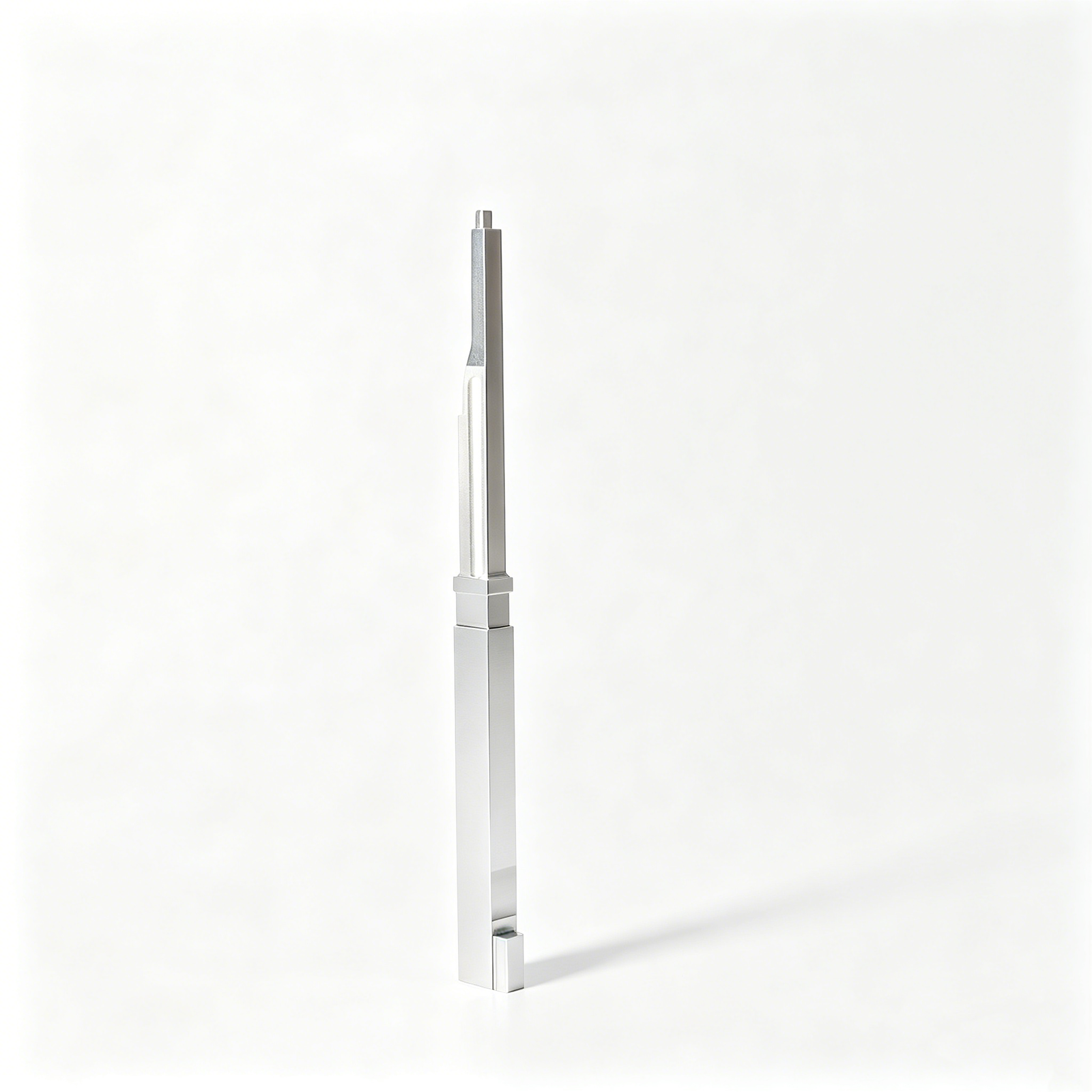
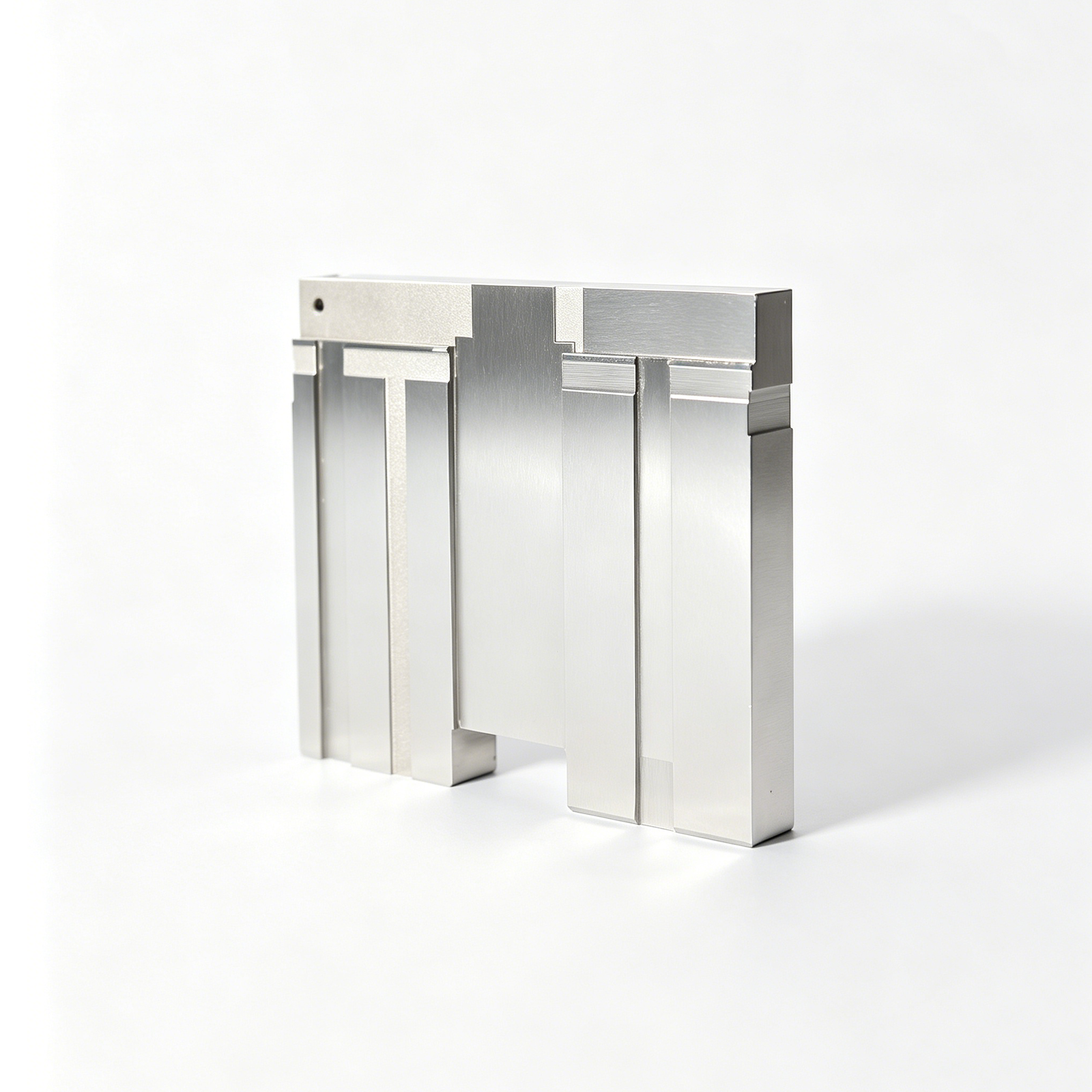
Representative Injection Mold Core and Cavity Components





Related Product Catalogue and Quotation






Injection Mold Cores and Cavities Engineering Advantages
Drawing-based planning aligns critical features, process access, inspection requirements, and revisions before production commitments are made.
DFM Before Quotation
Review drawings, models, material requirements, and application context to identify manufacturability questions before a process route or quotation is finalized.
Critical Dimension Planning
Define critical-to-quality dimensions, datum strategy, tolerance relationships, and surface priorities so machining and inspection address the features that matter.
Coordinated Process Routes
Plan CNC machining, wire or sinker EDM, grinding, fitting, and finishing around geometry, tool access, electrode needs, and machining allowance.
Inspection Method Alignment
Match the inspection plan and requested reporting to drawing requirements, measurement access, critical features, and order-specific quality expectations.
Visible Revision Control
Keep drawing revisions, open technical questions, manufacturing updates, and delivery information visible throughout drawing-based injection mold cores and cavities work.
Precision Mold Component Families
Discuss configurable components and process routes from your drawing, critical dimensions, material requirements, inspection expectations, and delivery schedule.

CNC Machining Services
Precision CNC machining services for drawing-based custom parts and mold components. Review datums, critical dimensions, material condition, machining access, and inspection requirements before selecting milling, turning, EDM, grinding, or fitting operations.
Upload a Drawing
CNC Milling
Custom CNC milling services support prismatic mold details, inserts, plates, pockets, and complex features. Tool access, corner radii, depth-to-width ratios, machining allowance, and datum relationships should be reviewed against the drawing before production planning.
Upload a Drawing
CNC Turning
Precision CNC turning services suit rotational features such as pins, sleeves, bushings, guide components, and custom cylindrical parts. Diameter tolerances, concentricity, runout, thread requirements, material condition, and downstream grinding needs guide the process route.
Upload a Drawing
5-Axis Machining
5-axis CNC machining can reduce setups for contoured, angled, and multi-face features where access and datum control matter. SUUXIANG reviews tool reach, fixture strategy, surface requirements, and inspection access from the supplied model and drawing.
Upload a Drawing
Swiss & Micro Machining
Swiss machining and micro machining support small, slender, and detail-intensive components where handling and feature geometry require disciplined planning. Discuss diameter tolerances, length-to-diameter ratio, material behavior, burr control, inspection method, and required quantity with the RFQ.
Upload a Drawing
Wire & Sinker EDM
Wire EDM services and sinker EDM services address profiles, narrow slots, sharp internal geometry, hardened workpieces, and features inaccessible to conventional cutting tools. Electrode strategy, wire path, flushing conditions, surface requirements, recast-layer considerations, and finishing allowances require drawing review.
Upload a Drawing
Precision Grinding
Precision surface and profile grinding supports controlled flatness, parallelism, profiles, and final-size requirements on suitable components. Grinding stock, heat-treatment sequence, datum selection, wheel access, surface specification, and inspection method should be agreed before machining begins.
Upload a Drawing
Mold Core & Cavity Inserts
Precision mold core inserts and mold cavity inserts are configurable from the part design, molding requirements, material specification, and mold-base interface. Review shutoff geometry, cavity detail, cooling or venting features, heat treatment, EDM needs, critical dimensions, and fitting relationships.
Upload a Drawing
Ejector & Ejection Components
Ejector pins, sleeves, and ejection components are planned around stroke, guidance, wear surfaces, clearance, material condition, and mating features. Provide drawings, pin or sleeve dimensions, surface needs, heat-treatment requirements, and the intended mold function for review.
Upload a Drawing
Core Pins, Guide & Locating Components
Core pins, guide pins, and locating components require controlled relationships to mating holes, inserts, and mold plates. SUUXIANG reviews diameter, concentricity, seating geometry, wear conditions, assembly datum, material, hardness, and inspection priorities from the drawing.
Upload a Drawing
Slides, Lifters, Gates & Mold Accessories
Mold slides, lifters, gates, and accessories are configurable components requiring attention to travel, shutoff surfaces, guiding, clearance, wear, and assembly interfaces. Provide the relevant drawing context so machining, EDM, grinding, fitting, and inspection can be planned appropriately.
Upload a Drawing
Connector Mold Components
Precision connector mold components support detailed tooling features for connector products, including inserts, cores, pins, and locating elements. Discuss cavity density, fine-pitch geometry, mating conditions, material, surface requirements, electrode strategy, and critical-dimensional inspection needs.
Upload a Drawing
Stamping Die Components
Precision stamping die components include drawing-based punches, dies, inserts, guides, and related wear parts. Process planning considers material, heat treatment, cutting-edge geometry, clearance, grinding stock, wire-EDM path, surface condition, and mating-component relationships.
Upload a Drawing
Injection, MIM, CIM & Overmolding Tooling
Injection, MIM, CIM, and overmolding tooling components are evaluated within verified production scope. Share the molding process, feed or gate context, material system, cavity requirements, critical features, thermal considerations, and inspection expectations before a manufacturing route is proposed.
Upload a Drawing
Machining Materials
CNC machining materials are selected against the drawing, application, machining behavior, heat-treatment sequence, corrosion or wear needs, and documentation requirements. Identify the specified grade, material condition, approved substitutions if any, and traceability expectations in the RFQ.
Upload a Drawing
Surface Finishes & Heat Treatment
Surface finishing and heat treatment must align with functional surfaces, dimensional priorities, material grade, and process sequence. Specify required finish, coating or treatment, hardness criteria, masking needs, grinding allowance, and any verification or reporting requirements before production.
Upload a Drawing
Quality, Metrology & Documentation
Precision inspection, metrology, and quality documentation are planned around critical dimensions, datums, tolerances, surface requirements, and customer-defined reporting needs. Submit the drawing revision, measurement priorities, inspection method expectations, and traceability requirements with the inquiry.
Upload a Drawing
Prototyping & Low-Volume Production
Rapid prototyping and low-volume manufacturing support drawing-driven evaluation, tooling development, engineering changes, and controlled small-batch needs. Define quantity, revision status, material, critical features, quality documentation, target date, and application context for a practical review.
Upload a DrawingMaterials for Injection Mold Cores and Cavities

Pre-Hardened Tool Steel
A practical starting point for many core and cavity inserts where stable machining, controlled hardness, and service requirements must be balanced. Grade selection, heat-treatment condition, and finish requirements should be confirmed during RFQ review.

Hardenable Tool Steel
Suitable for demanding injection mold cores and cavities that may require higher wear resistance after machining and heat treatment. DFM review should define grinding allowance, EDM sequence, distortion risk, and critical-dimension inspection before production.

Stainless Tool Steel
Considered where corrosion resistance, polishability, or moisture-related molding conditions influence component performance. The specified grade, hardness target, surface finish, and mating conditions should be verified against the drawing and application requirements.

Tungsten Carbide
Used selectively for high-wear details, abrasive molding materials, and compact features requiring exceptional resistance to deformation. Carbide geometry, support design, EDM or grinding access, and inspection method require project-specific engineering review.

Copper Alloys
Applied to selected inserts or localized features when thermal conductivity is a key design consideration. Alloy choice must account for strength, wear exposure, joining or fitting method, and the molding application’s cooling and maintenance needs.

Engineering Alloy Metals
Used for specialized core, cavity, or insert requirements where a standard tooling steel is not the right fit. Material certification, machinability, heat treatment, and dimensional priorities should be aligned before quotation and process planning.
Injection Mold Cores and Cavities: CNC, EDM and Grinding Processes

CNC Milling
CNC milling develops core and cavity forms, pockets, faces and functional features from the approved drawing and model. Tool access, stock allowance and critical-dimension priorities are reviewed to establish a controlled machining route.


Wire EDM
Wire EDM produces accurate through profiles, insert openings, narrow features and geometry requiring a controlled wire path. SUUXIANG reviews start-hole access, datum references, wire-cut allowances and required surface or fitting conditions before release.

Sinker EDM
Sinker EDM addresses deep ribs, fine grooves, sharp internal geometry and features with limited cutter access. Electrode strategy, flushing access, machining allowance and the required finish are considered alongside the specified core or cavity geometry.

Grinding and Inspection
Precision grinding and inspection complete dimensional relationships, mating surfaces and critical features after the planned machining sequence. Measurement methods, reporting needs, revision status and acceptance criteria are aligned to the order-specific inspection plan.
Injection Mold Cores and Cavities: Tooling Features

Core Pins
Core pins form holes, internal details, and localized geometry within the molding tool. Drawing review confirms pin diameter, seating method, material requirement, clearance, and replacement considerations before machining and inspection planning.

Guide Elements
Guide pins, bushings, and related guidance elements support repeatable alignment between mold halves and moving components. Selection depends on mold layout, load path, locating accuracy, lubrication approach, and specified fit conditions.

Locating Components
Locating rings, dowels, keys, and datum features establish controlled relationships among inserts, plates, and mold assemblies. SUUXIANG reviews assembly interfaces, reference datums, tolerance stack, and inspection points against the supplied drawing.

Gate Inserts
Gate inserts support defined material entry and can be configured around gate geometry, wear considerations, and serviceability needs. Tool access, EDM strategy, surface requirements, and mating interfaces should be confirmed during DFM review.

Ejector Parts
Ejector pins, sleeves, blades, and related ejection components help release molded parts without damaging critical surfaces. Feasibility depends on ejection location, guide conditions, clearance, hardness requirements, and the surrounding core geometry.

Custom Inserts
Custom inserts enable localized geometry changes, replaceable wear areas, or complex details within injection mold cores and cavities. Drawing-based review defines interfaces, fastening, machining route, heat-treatment sequence, grinding stock, and inspection requirements.
About SUUXIANG Injection Mold Cores and Cavities
SUUXIANG is the international-facing brand of Dongguan SuuXiang Precision Mold Co., Ltd., established in 2010 in Chang’an Town, Dongguan, Guangdong, China. We help global engineering, sourcing and quality teams convert drawings, models and specifications into inspected precision mold components and custom CNC-machined parts.
For injection mold cores and cavities, our work begins with a practical review of critical dimensions, datums, material and heat-treatment requirements, surface expectations, machining access and inspection needs. CNC machining, EDM, grinding, fitting and controlled project coordination are selected around the drawing rather than treated as a generic process list.
What distinguishes SUUXIANG is disciplined communication before production: DFM questions, revision control, process planning and inspection expectations are made visible early. This supports connector tooling, mold components, stamping-die components and low-volume custom work where traceability and manufacturability matter as much as the quoted part.

Injection Mold Cores and Cavities: Controlled Manufacturing
DFM and Datum Strategy
Before quotation, SUUXIANG reviews the drawing, model, functional interfaces and critical dimensions for injection mold cores and cavities. The discussion establishes datum references, tolerance relationships, machining access and risks that could affect fit, molding performance or inspection.
- Identify critical-to-quality dimensions and mating interfaces
- Confirm datum scheme and tolerance-stack priorities
- Review draft, parting-line and feature-access constraints
- Clarify material, heat treatment and surface requirements

CNC and EDM Planning
Process planning assigns each feature to an appropriate route across CNC milling, turning, multi-axis machining, wire EDM and sinker EDM. Electrode geometry, wire paths, corner conditions and finishing sequence are reviewed against the approved drawing before production begins.
- Match feature geometry to CNC, wire EDM or sinker EDM
- Assess electrode access and burn-direction requirements
- Plan machining allowances before finish operations
- Keep approved revisions visible through production

Grinding and Fitting Control
Precision grinding and fitting are planned as controlled finishing steps, not afterthoughts. SUUXIANG evaluates grinding stock, heat-treatment sequence, bearing surfaces and assembly relationships so cores, cavity inserts and related components can be finished against the required functional references.
- Define grinding stock for critical faces and diameters
- Coordinate heat treatment with finishing operations
- Check sliding, locating and shutoff relationships
- Protect functional surfaces during fitting and handling

Inspection and Revision Delivery
Inspection planning follows the drawing’s critical dimensions, specified datums and agreed reporting needs. SUUXIANG coordinates final inspection records, part identification and delivery information with the approved revision, helping sourcing and quality teams maintain traceability from RFQ through receipt.
- Align inspection method with critical feature requirements
- Confirm report scope before production release
- Maintain revision-controlled drawing communication
- Provide order-matched delivery and inspection documentation

Why Choose SUUXIANG for Injection Mold Cores and Cavities
Compare drawing-led planning, inspection alignment, and revision visibility against a quote-only sourcing approach.
← Swipe left or right to view →
Injection Mold Cores and Cavities: Drawing to Inspected Parts
A drawing-led workflow that keeps manufacturability, critical dimensions, process decisions, inspection requirements, and delivery coordination visible from RFQ through dispatch.
Review RFQ Package
We review drawings, models, material, quantity, application context, target date, and reporting needs; unclear critical dimensions or revision details are identified before quotation.
Plan Process Route
DFM discussion confirms datums, tolerance stack, machining access, heat-treatment sequence, grinding stock, and the required CNC, EDM, grinding, or fitting operations.
Machine Core Components
Approved plans guide CNC milling, turning, multi-axis work, wire EDM, and sinker EDM for injection mold cores and cavities with controlled revision information.
Grind And Fit
Grinding, finishing, and fitting address functional interfaces, locating features, mating surfaces, and specified surface requirements while preserving planned datum relationships.
Inspect And Coordinate Delivery
Parts are inspected against the agreed plan, documentation is matched to the order, and packing and delivery coordination follow verified release information.
How to Source Injection Mold Cores and Cavities
A controlled, drawing-led path from initial review through inspected delivery.
Submit Your Drawing Package
Send 2D drawings, available 3D models, material and heat-treatment requirements, quantity, critical dimensions, surface priorities, delivery target, and inspection or reporting expectations.
Align DFM and Quote Scope
Review datums, tolerance stack, machining access, EDM strategy, grinding allowance, fitting needs, and revision status before SUUXIANG defines a traceable quotation scope.
Approve Production Details
Confirm the agreed drawing revision, material route, critical-to-quality features, inspection method, and delivery requirements before machining, EDM, grinding, fitting, and controlled project coordination proceed.
Receive Inspected Parts
Receive completed components with order-matched inspection documentation and visible revision and delivery information, supporting incoming-quality review and the next tooling or assembly decision.
Certification and Quality Documentation
Injection Mold Cores and Cavities: Customer Outcomes
The drawing-review notes identified three datum conflicts before machining began. After the revision was aligned, the core inserts arrived with the requested inspection results, allowing our toolroom to proceed without a second clarification cycle.
For a six-insert cavity update, SUUXIANG kept revision status visible across two drawing releases and provided dimensional evidence for the 12 critical features we identified. That gave our supplier-quality review a clear, traceable basis for acceptance.
The team raised EDM access and grinding-stock questions before quoting our injection mold cores and cavities. That early feedback helped us release a manufacturable revision, and the low-volume tooling parts were delivered against the agreed inspection plan.
Injection Mold Cores and Cavities FAQ
Practical answers for drawing-based sourcing, from DFM inputs and material requirements to inspection, revisions and delivery coordination.
What is the MOQ for injection mold cores and cavities?
What should I send for a quotation on injection mold cores and cavities?
Can SUUXIANG provide samples before repeat production of injection mold cores and cavities?
How should I plan lead time for a custom mold core or cavity insert?
Which material and heat-treatment details do you need?
What inspection reports can be requested with the order?
How are injection mold cores and cavities protected for international shipping?
How do you control drawing revisions and protect project information?
Buyer’s Guide to injection mold cores and cavities
Use this decision framework to specify core-and-cavity tooling, compare material and construction choices, evaluate capable suppliers, control cost drivers, and avoid design, quality, and launch mistakes before production.
1. What Are injection mold cores and cavities?
Two mating mold features define the part-forming space: the cavity generally creates the exterior surfaces, while the core forms interior geometry such as bores, ribs, or recesses. They are complementary features, not interchangeable labels; their separation establishes the parting direction and release path. https://www.xometry.com/resources/injection-molding/injection-molding-core-and-cavity
Four basic cycle stages are plastification, injection into the closed tool, packing/cooling, and mold opening. As the polymer cools and shrinks, the part is typically retained on the core side, where ejector pins or another ejection mechanism can push it free. https://www.xometry.com/resources/injection-molding/injection-molding-core-and-cavity
One core-to-cavity relationship governs more than shape: alignment and datum control influence wall thickness, flash risk, critical dimensions, and repeatability from shot to shot. Surface texture, draft, cooling behavior, venting, and the chosen ejection contact areas also determine whether the molded surface releases cleanly without deformation or visible marking.
2. Evolution of injection mold tooling
1950s-era numerical-control machining began replacing heavily manual toolmaking for repeatable prismatic features. Standardized mold bases then separated common structural hardware from product-specific inserts, making repair, design changes, and multi-cavity scaling more manageable.
1960s CNC expanded programmed milling for contoured surfaces, while wire EDM and sinker EDM made sharp internal corners, narrow ribs, and difficult-access geometry practical. Buyers now need the proposed split line, electrode strategy, wire path, and datum scheme reviewed together rather than treating each process as independent.
Interchangeable inserts shifted many high-wear or revision-prone features from permanent blocks into replaceable components. That approach can shorten iteration cycles and localize maintenance, provided insert retention, sealing, cooling interfaces, and inspection datums are defined on the drawing.
3D metal additive manufacturing enabled conformal cooling channels that can follow complex cavity geometry where conventional drilled circuits cannot. Modern CMMs, optical measurement, and documented inspection plans let teams compare injection mold cores and cavities against critical dimensions before assembly, supporting traceable approval and scalable production.
3. Types of injection mold cores and cavities
Feature-forming cores determine how geometry releases; cavity count determines how many identical parts run per cycle. Review these choices separately before tool layout, because each changes access, ejection, balance, and service planning.
| Configuration | Need Addressed | Benefit | Buyer Resolution |
|---|---|---|---|
| Fixed | Simple release geometry | Lowest mechanism burden | Draft and ejection side? |
| Interchangeable insert | Localized revision or wear | Replaceable feature | Insert datum and spare plan? |
| Split or collapsible | Internal undercut | Permits release | Actuation clearance and service access? |
| Side-action or lifter | External or internal undercut | Forms return feature | Slide travel, shutoff, witness line? |
| Unscrewing | Functional thread | Protects thread form | Thread standard, pitch, cycle target? |
| Multi-cavity | Higher output demand | More parts per cycle | Cavity count, balance, traceability? |
Feature-Forming Options
Undercuts, internal threads, and deep return features require motion or removable tooling beyond a fixed core. Confirm draft, shutoff locations, travel, ejection side, and allowable witness lines on the drawing.
Cavity Count Decisions
Multi-cavity tooling multiplies output, but it does not create a different part feature. Confirm annual volume, cavitation target, runner or hot-runner concept, gate balance, part-to-part inspection criteria, and spare-component expectations.
4. Materials for injection mold cores and cavities
Material choice for injection mold cores and cavities is a lifecycle decision, not a catalog selection. Compare resin chemistry, required finish, annual volume, cooling demand, validation evidence, and replacement risk before releasing a grade.
| Material | Wear | Corrosion | Thermal | Machinability | Cost |
|---|---|---|---|---|---|
| Pre-hardened steel | Medium | Low | Medium | Good | Medium |
| Hardened steel | High | Low | Medium | Lower | High |
| Stainless steel | Medium | High | Medium | Medium | High |
| Aluminum | Low | Medium | High | High | Low |
| Copper alloy insert | Low | Medium | Very high | Medium | High |
Steel Selection
Pre-hardened steel shortens machining and suits moderate production. Hardened tool steel raises wear resistance for abrasive resins and higher-volume duty, but adds heat-treatment, EDM, and grinding planning.
Corrosion And Thermal Inserts
Stainless grades are evaluated where moisture, corrosive resin byproducts, or storage conditions threaten surfaces. High-conductivity copper-alloy inserts can remove heat from local hot spots, but require support and wear review.
Prototype Tradeoffs
Aluminum can accelerate selected prototype tools because it machines quickly and transfers heat well. Its lower wear margin makes resin abrasiveness, shot count, geometry, and repair strategy essential inputs.
5. Customizing injection mold cores and cavities
Customization should start with the part’s function, resin, cosmetic requirement, and planned maintenance interval. For injection mold cores and cavities, each optional feature changes machining, inspection, and service decisions.
| Option | Functional Link | Maintenance Evidence |
|---|---|---|
| Interchangeable insert | Wear or revision zone | Datum and spare plan |
| Texture or polish | Cosmetic surface and resin | Finish reference sample |
| Vent or cooling | Fill balance and heat removal | Cleaning and leak access |
| Gate or ejection | Appearance and release | Vestige and mark limits |
Specify Replaceable Inserts
One replaceable insert can localize wear, engineering revisions, or family-part changes without remachining the complete tool.
A drawing should define insert datums, retention, shutoff surfaces, interchangeability limits, and spare-part expectations.
Match Surface To Function
A defined polish grade, texture, engraving, coating, or treatment should correspond to resin behavior and the molded surface requirement.
Mold-surface engraving creates the part feature; printing, plating, and other decoration applied after molding are separate processes.
Coordinate Flow And Release
Gate interface, vent location, cooling layout, and ejection provisions must be reviewed together because they affect fill, cosmetic appearance, warpage, and release.
The RFQ should identify acceptable gate vestige, ejector-mark zones, vent-cleaning access, and cooling-service access.
6. Construction quality elements
Two mold halves can produce stable parts only when their interfaces, support, thermal paths, and release features are designed as one system. Review these details against the drawing’s datums and critical dimensions before steel is cut.
Parting Lines And Shutoffs
Parting lines should sit on noncritical surfaces where witness marks are acceptable, while shutoffs need adequate land and support. Thin, poorly supported shutoffs wear or deflect, causing flash, mismatch, and uneven dimensions.
Alignment And Steel Safety
Four construction controls—leader guides, bushings, support pillars, and core/cavity datums—resist platen load and repeated closing error. Steel-safe allowance on change-prone dimensions permits controlled fitting; removing steel prematurely can force a costly insert revision.
Flow Cooling And Release
Draft, gate location, balanced cooling, vents, and ejection must be reviewed together around the intended shrinkage direction. Insufficient draft causes sticking, restricted vents create burn marks or short shots, and uneven cooling or pin loading can create warp and ejector damage.
Serviceable Wear Areas
Replaceable inserts should protect gates, shutoffs, slides, and other high-wear or damage-prone features where practical. Accessible fastening and datum-controlled replacement shorten maintenance while preserving alignment after an insert is changed.
7. How to choose a manufacturer
Two comparable quotations can conceal different engineering effort. For injection mold cores and cavities, assess the evidence behind the route, controls, and delivery commitments before comparing price.
| Evaluation Area | Evidence To Request | Quotation Comparison |
|---|---|---|
| DFM review | Marked drawing and risk list | Assumptions and rework exposure |
| Inspection | CTQ plan and report format | Measurement scope |
| Change control | Revision log and deviation route | Approval and communication discipline |
Verify Drawing Review
At RFQ, request marked-up 2D drawings or a review log identifying datums, CTQ dimensions, tool access, EDM electrodes, wire paths, grinding stock, and unresolved assumptions.
For connector programs, confirm the supplier questions mating interfaces, pin locations, flash-sensitive edges, and revision status before releasing work.
Compare Process Evidence
Before award, match each critical feature to CNC, wire EDM, sinker EDM, grinding, fitting, and inspection methods. Request material identification and heat-treatment records when the drawing or quality plan requires traceability.
Control Approval And Changes
During first-off approval, require a defined sample plan, dimensional report, deviation process, and revision-controlled documentation. After delivery, establish one technical contact and a response path for fit findings or corrective-action evidence.
8. Common buyer mistakes to avoid
Before tool release, confirm the production inputs, not just the nominal part geometry. Most avoidable rework in injection mold cores and cavities starts when a drawing leaves decisions implicit.
Lock Material And Geometry
Resin grade, filler content, shrinkage direction, and draft must accompany the drawing; omissions can create undersize parts, drag marks, or an unworkable release direction. Provide the resin data sheet, shrinkage assumption, draft callouts, datums, and mating context for DFM review.
Specify Tooling Risks
Steel selected only on purchase price can wear, corrode, or polish poorly in service; unclear cosmetic zones can place EDM texture, parting lines, or ejector marks on visible faces. Define resin abrasiveness, expected duty, surface zones, permissible witness marks, inserts, and every undercut before the process route is fixed.
Approve Production Evidence
Cooling and venting omitted from review can cause warp, burns, short shots, or unstable cycle behavior; missing inspection criteria makes acceptance subjective. Identify critical dimensions, measurement methods, sampling, report format, and cooling-sensitive areas.
A revision identified only by email can put superseded geometry into manufacture. Release one controlled drawing and model revision, record deviations in writing, and require acknowledgement before machining begins.
9. Launch steps from drawing to approval
A controlled launch for injection mold cores and cavities converts a drawing package into accountable decisions. Set approval gates before machining so engineering, quality, procurement, and the supplier use the same revision and acceptance criteria.
Prepare The Release Package
The buyer supplies the 2D drawing, 3D model, resin, annual-volume assumption, mating-part context, and target date. Quality identifies CTQ dimensions, datums, surface requirements, and required inspection records.
The supplier logs the revision, open questions, and document owner. Procurement retains the RFQ, clarified quotation scope, and agreed change-control path.
Close DFM And Tool Concept
The DFM review resolves parting line, draft, shrinkage assumption, gate concept, ejection, cooling, tool access, EDM needs, and grinding allowance. Engineering approves the technical direction only after unresolved risks have an owner and due date.
The quotation states included components, material and heat-treatment assumptions, inspection scope, trial responsibility, and exclusions. A released drawing and approved scope are the machining gate.
Trial, Approval, And Spares
Manufacturing follows the released revision and inspection plan, then records component results before assembly. Trial samples are assessed against dimensional, cosmetic, functional, and process-window criteria defined in advance.
Any correction receives a revision record and reapproval before production release. Maintenance retains as-built drawings, inspection reports, trial data, spare-part list, and wear observations for future service.
10. Injection mold core and cavity pricing
1 tooling quote should separate non-recurring engineering and toolmaking from the molded-part price. For injection mold cores and cavities, the latter typically falls as validated cavities produce more parts per cycle, while the former rises with engineering risk.
2 cost reviews should compare cavity count, steel grade, geometry, undercuts, surface finish, cooling layout, tolerances, inspection and likely revisions. Slides, lifters, electrodes, wire-EDM paths, close-tolerance grinding and extra inspection points add programming, machining, fitting and verification effort.
3 RFQ inputs reduce avoidable rework: provide the drawing, 3D model, resin, expected annual volume, cosmetic surfaces, critical datums and revision status. Ask the supplier to identify one-time charges, assumptions, sampling requirements and the change-control cost before release.
| Project route | Relative tooling cost | Lead-time effect | Suitable use case |
|---|---|---|---|
| Single cavity, simple insert | Lower | Shortest | Prototype or low volume |
| Multi-cavity, balanced cooling | Higher | Longer | Stable higher-volume demand |
| Undercuts or high-polish features | Higher | Longer | Complex functional or cosmetic parts |
Upload Injection Mold Cores and Cavities Drawings
Submit your 2D drawing, 3D model where available, material, quantity, quality priorities, and target delivery date for a scoped manufacturing review.