
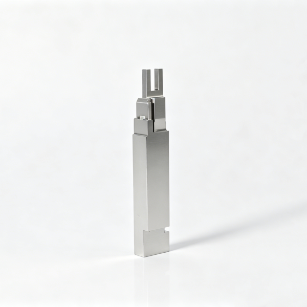
Drawing-Controlled Forked Core Insert with Protected Projecting Legs
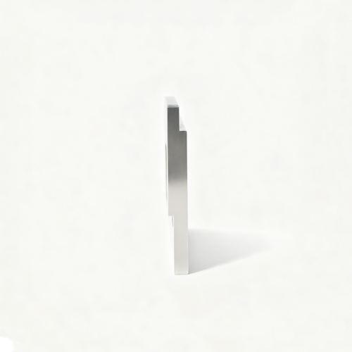
This custom forked insert is intended for a drawing-based mold-component RFQ where projecting legs, their spacing, and their relationship to the base must remain controlled. The gallery image is a visual reference to a forked form, not proof of fixed dimensions, leg count, material, tolerance, application, or manufacturing history. The correct route depends on the approved drawing, feature access, material condition, mounting datum, and the degree of protection required during machining and inspection.
Forked insert planning focused on leg stability, central relief, mounting references, and non-deflecting measurement.
Define the Fork in the Drawing Package
The RFQ should show the complete base, mounting features, projecting geometry, central relief, and every datum used to locate the fork. Include a controlled drawing revision, units, three-dimensional model if available, material direction if already selected, thermal instructions if applicable, surface notes, and required inspection records. Enlarged sections should clarify tip form, corner condition, root transitions, relief depth, and any edge break.
Stabilize the Projecting Legs
Projecting legs may release stress differently from the body and can be damaged by unsupported handling. A conditional manufacturing route may use symmetrical roughing so material removal is balanced around the fork. Temporary support can remain in place until late operations where the drawing permits it. This support should be planned rather than improvised, because an unreviewed bridge or holding land may obstruct the relief, alter access, or leave an unacceptable witness.
Clamping pressure and probing force also matter. The legs may deflect during setup even when they return afterward, creating misleading measurements or damage at the tips. Soft contact zones, protected trays, and controlled orientation can reduce handling risk. The final leg inspection should be performed only after the intended support condition is defined and the part is clean, stable, and free from loose burrs.
Choose a Route for the Central Relief
The central relief may be machined, wire-cut, or sinker-EDM processed depending on its shape, depth, access, corner requirements, and approved material condition. Wire EDM can be considered where a through-slot and suitable entry conditions make it practical. Sinker EDM may be considered for a blind or difficult-to-access cavity. Conventional or micro-machining may be suitable when cutter access, chip evacuation, and wall stability are acceptable.
The method should be selected feature by feature. EDM may influence edge condition, recast, corner sharpness, or taper expectations. Cutting may introduce burrs, tool deflection, or stress at the leg roots. A relief that looks open in a photograph may still be difficult to finish without overcut, taper, or a damaged transition. The drawing should state whether the slot corners, root radii, sidewalls, and bottom form are functional.
Protect the Base Relationship
Before inspecting the legs, finish the mounting references that establish the insert’s position. These may include a base plane, shoulder, locating side, bore, or other drawing-defined datum. The objective is to create a reliable relationship between the fork and the component that receives it. Measuring leg spacing alone is insufficient if the entire fork is offset from the mounting datum.
Assembly decisions should be explicit. Identify whether the base seats against a plane, locates against a shoulder, slides into a pocket, or requires a controlled clearance. If the forked feature must align with a mating form, show the relevant datum chain. This prevents a visually symmetrical part from receiving an incorrect fit decision. No fixed clearance, tolerance, or surface finish should be inferred without the approved drawing.
Manage Material and Edge Condition
This product page does not assign a fixed material, hardness, coating, or heat-treatment route. Those details must come from the customer drawing and engineering review. If thermal processing or stress relief is required, the sequence should account for possible movement before final leg and relief work. Where the material remains open, quote assumptions should be clearly separated from confirmed requirements.
Leg tips and inner relief edges require particular attention. A sharp edge, defined radius, controlled break, or polished transition can change both function and inspection method. A finishing pass may improve a plane while rounding a tip; deburring may remove an intended edge; EDM may alter a small corner. Name the surfaces and conditions that matter, then agree how they will be protected, processed, and accepted.
Inspect Without Deflecting the Fork
Inspection should cover leg width, spacing, parallelism, tip form, and position relative to the base datum, but the method must not bend the legs. Optical measurement, magnified visual review, and datum-based dimensional checks may be combined according to the actual scale and accessibility. Contact probing can be considered only where contact force, support, and stylus access will not change the result.
The report should identify the support condition and reference system. Check whether the legs are free-state, supported at the base, held by a defined fixture, or measured in another controlled condition. Review root transitions, central relief walls, tip damage, burrs, taper, and overcut in addition to numeric dimensions. If parallelism or position is critical, relate it to the approved datum rather than comparing the legs to an arbitrary machine axis.
Control the Forked-Insert RFQ
Send the latest controlled drawing, revision, model, quantity, units, material direction, thermal instructions, surface requirements, and inspection-document expectations. Mark the base datums, leg features, relief, functional edges, and any surfaces that must remain protected. If the photo is being used for visual comparison, label it as reference-only and keep it separate from contractual geometry.
Frequently Asked Questions
Are the legs guaranteed to match the image?
No. The image shows a general forked form; the approved drawing defines the actual geometry.
Can wire or sinker EDM be used for the relief?
Either may be considered when access and geometry warrant it. The choice depends on slot form, depth, corners, taper, and material condition.
How are thin legs measured?
Measure them from defined base datums with optical or otherwise non-deflecting methods and document the support condition.
Send the Forked-Insert Drawing
Provide the controlled geometry and datum requirements for a leg-protection and inspection review.
Reviews
There are no reviews yet.