
Injection Mold Tooling Components for Drawing-Based Production
From RFQ and DFM review to inspected CNC-machined tooling components, SUUXIANG supports drawing-based production with revision control and defined inspection requirements.
Representative Injection Mold Tooling Components





Related Tooling Components and Drawing-Based Quotations







Injection Mold Manufacturing Advantages for Drawing-Based Tooling
A disciplined workflow for translating drawings into precision tooling components with visible decisions at every manufacturing stage.
DFM Before Quotation
Drawing review identifies manufacturability concerns, tool access, datum strategy, and process risks before quotation or production commitments are made.
Critical Dimension Focus
Critical-to-quality dimensions, surface priorities, and tolerance relationships are reviewed to align machining, EDM, grinding, and inspection decisions.
Coordinated Process Routes
CNC machining, wire or sinker EDM, precision grinding, and fitting are planned as connected operations rather than isolated processes.
Inspection Planning
Inspection methods and reporting needs are defined against the drawing and order requirements, with attention to relevant datums and features.
Revision-Controlled Communication
Drawing revisions, technical decisions, and delivery information remain visible throughout the project to support traceable engineering communication.
RFQ-Ready Collaboration
Material, heat treatment, quantity, application context, quality expectations, and delivery targets help establish an informed manufacturing discussion.
Precision Mold and Tooling Components
Drawing-driven process routes for configurable mold, connector, die and custom-machined components, reviewed against critical dimensions, material requirements and inspection needs.

CNC Machining Services
Precision CNC machining services for custom machined parts requiring coordinated milling, turning, EDM, grinding and inspection. Drawing review identifies critical dimensions, datums, material condition, tool access and inspection requirements before a process route and quotation are prepared.
Upload a Drawing
CNC Milling
Custom CNC milling services for prismatic parts, mold plates, inserts and complex features. Toolpaths are planned around datum strategy, cutter access, wall geometry, machining allowance and surface requirements so critical features can be measured against the agreed drawing revision.
Upload a Drawing
CNC Turning
Precision CNC turning services for rotational components such as pins, sleeves, bushings and locating features. Review focuses on concentricity, runout, shoulder transitions, thread requirements, material condition and the relationship between turned features and subsequent grinding or EDM.
Upload a Drawing
5-Axis Machining
5-axis CNC machining supports multi-face and contoured features where repositioning can introduce datum transfer risk. Feasibility depends on tool reach, workholding, feature orientation, corner geometry, material behavior and the inspection method required for critical surfaces.
Upload a Drawing
Swiss & Micro Machining
Swiss machining and micro machining support small, slender and detail-intensive components where stability and feature sequence matter. A drawing review should define material, diameter transitions, tolerances, surface needs, burr control and inspection criteria before production planning.
Upload a Drawing
Wire EDM Services & Sinker EDM Services
Wire EDM and sinker EDM services address hardened materials, narrow profiles, internal corners, deep cavities and features with limited cutter access. Electrode strategy, wire path, flushing, stock condition and recast-layer considerations are reviewed against functional requirements.
Upload a Drawing
Precision Grinding
Precision surface and profile grinding supports flatness, parallelism, profile control and fine finishing after machining or heat treatment. The process plan accounts for grinding stock, distortion risk, datum preservation, surface requirements and measurement access for critical features.
Upload a Drawing
Mold Core & Cavity Inserts
Precision mold core and cavity inserts are produced to the drawing-defined geometry, material and surface requirements of the molding application. Review covers parting surfaces, shutoffs, cooling interfaces, EDM needs, heat-treatment sequence, fitting relationships and inspection points.
Upload a Drawing
Ejector & Ejection Components
Ejector pins, sleeves and ejection components are planned around fit, guidance, wear surfaces and motion within the mold assembly. Drawings should identify diameters, clearances, material or treatment needs, surface condition and any mating-component constraints.
Upload a Drawing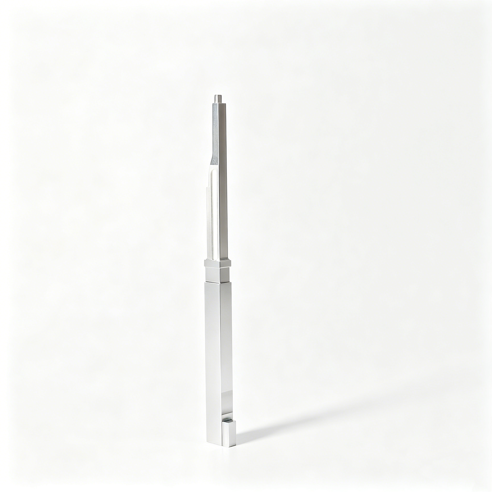
Core Pins, Guide & Locating Components
Core pins, guide pins and locating components require controlled relationships between functional diameters, shoulders, engagement lengths and assembly datums. Process planning considers material, heat treatment, grinding needs, wear conditions and the inspection approach for fit-critical features.
Upload a Drawing
Slides, Lifters, Gates & Mold Accessories
Mold slides, lifters, gates and accessories are configured from the drawing and assembly function rather than treated as stock items. Review considers travel interfaces, angled surfaces, shutoffs, wear points, cooling or gating geometry, fitting needs and revision-controlled mating dimensions.
Upload a Drawing
Connector Mold Components
Precision connector mold components support small-pitch, repeatable tooling features where alignment, cavity detail and wear behavior are central. The production review examines critical geometry, material condition, EDM or grinding strategy, mating interfaces and inspection requirements before commitment.
Upload a Drawing
Stamping Die Components
Precision stamping die components are manufactured for the functional relationships of forming, cutting, guiding and locating operations. Review covers working edges, clearances, material and hardness requirements, grinding allowance, wear surfaces, assembly datums and measurement expectations.
Upload a Drawing
Injection, MIM, CIM & Overmolding Tooling
Injection, MIM, CIM and overmolding tooling components are evaluated within verified production scope. Drawing review addresses feed and vent features, shrinkage-related interfaces, cavity detail, material requirements, EDM access, polishing needs and inspection criteria for the specified application.
Upload a Drawing
Machining Materials
CNC machining materials are selected against drawing requirements, function, machinability, heat-treatment sequence and inspection needs. Provide the specified grade, material condition, approved alternatives where applicable, and application context when material behavior affects the process route.
Upload a Drawing
Surface Finishes & Heat Treatment
Surface finishing and heat treatment are planned as controlled requirements, not generic add-ons. Define the required finish, hardness or treatment condition, critical surfaces, masking needs, dimensional sensitivity and whether post-treatment grinding or inspection is required.
Upload a Drawing
Quality, Metrology & Documentation
Precision inspection, metrology and quality documentation are aligned to the order and agreed inspection plan. Buyers should identify critical dimensions, datums, report format, sampling expectations, traceability needs and the drawing revision that governs acceptance.
Upload a Drawing
Prototyping & Low-Volume Production
Rapid prototyping and low-volume manufacturing support drawing-driven validation, bridge quantities and controlled production runs. Quote preparation should include quantity, material, critical dimensions, surface priorities, inspection needs, target delivery date and any revision or assembly context.
Upload a DrawingInjection Mold Manufacturing Materials for Tooling Components

Pre-Hardened Tool Steel
A practical choice for mold bases, plates, and moderately demanding inserts. Its supplied condition can reduce heat-treatment steps, but machining allowances, hardness requirements, and final inspection criteria should be confirmed from the drawing.

Hardenable Tool Steel
Used for cores, cavity inserts, slides, and wear-sensitive tooling features that require a planned hardening route. SUUXIANG reviews EDM access, grinding stock, distortion risk, and critical datums before committing to the process.

Stainless Tool Steel
Suitable where corrosion resistance, surface condition, or polished cavity performance influences material selection. Grade, heat-treatment condition, molding environment, and surface-finish expectations should be defined so machining and inspection plans align with the application.

Copper Alloy Inserts
Applied selectively to inserts requiring improved heat transfer or localized thermal control. Alloy selection must consider strength, wear exposure, machining behavior, and the interface with surrounding tool steel before production planning begins.

Engineering Aluminum Alloys
Often considered for prototype tooling, fixtures, and lower-load component applications where machining efficiency matters. Confirm the alloy, operating conditions, dimensional priorities, and expected production use during drawing review to determine suitability.
Injection Mold Manufacturing Process Routes

CNC Milling
CNC milling forms plates, cores, cavity inserts and complex features from drawing-driven toolpaths, with machining access, datum strategy and remaining stock reviewed before downstream EDM or grinding.

CNC Turning
CNC turning produces rotational features such as pins, sleeves, bushings and locating elements, using specified datums and material condition to support controlled fits and subsequent finishing where required.

Wire EDM
Wire EDM cuts precise profiles, narrow slots and hardened features where conventional cutter access is limited. Wire path, start-hole access, corner conditions and finish expectations are reviewed against the drawing.

Sinker EDM
Sinker EDM creates deep, detailed or difficult-to-reach cavity features using a planned electrode strategy. Electrode geometry, burn allowance, surface requirement and later fitting needs guide the applicable route.


Fitting Inspection
Fitting and inspection verify functional relationships between components, including mating interfaces, movement and critical dimensions. Documentation is aligned with the agreed inspection plan, revision status and order requirements.
Injection Mold Manufacturing Features and Tooling Accessories

Guide Components
Guide pillars, bushings, and related locating features help control repeatable mold-half alignment. Define mating relationships, fit expectations, material requirements, and critical datums so the appropriate machining, grinding, and inspection route can be reviewed.

Locating Elements
Dowel holes, locating pins, keys, and reference features establish repeatable assembly positions between plates and inserts. Provide datum references and tolerance priorities to support a practical machining sequence and verification plan.

Gate Inserts
Configurable gate inserts support the specified resin-entry geometry and replacement strategy. Drawing review should address gate location, steel condition, EDM or milling access, polish requirements, and the interfaces affecting fitting.

Slide Components
Slides and associated wear, guide, and shutoff features can address side actions or undercut-related tooling requirements. Share travel, mating geometry, clearance expectations, and critical surfaces for a manufacturability review.

Lifter Elements
Lifters provide a configurable route for releasing selected molded features during tool opening and ejection. Review angle, travel, bearing surfaces, interference risks, heat-treatment requirements, and inspection points from the approved drawing.

Ejector Components
Ejector pins, sleeves, blades, and related retention features support the planned part-release system. Identify pin locations, working surfaces, fit classes, hardness requirements, and cosmetic constraints before component production is committed.
About SUUXIANG Injection Mold Manufacturing
SUUXIANG is the sole international-facing brand of Dongguan SuuXiang Precision Mold Co., Ltd., established in 2010 in Chang’an Town, Dongguan, Guangdong, China. Founded by legal representative XiaoCheng Huang, the company helps global engineering, sourcing and quality teams convert drawings and specifications into inspected precision mold components, connector tooling, die components and custom CNC-machined parts.
Our injection mold manufacturing support is built around practical process planning: CNC milling and turning, multi-axis machining, wire and sinker EDM, precision grinding, fitting, and inspection. Each route is selected against the drawing, material condition, critical dimensions, tool access, EDM needs, grinding allowance, and required documentation.
What differentiates SUUXIANG is a disciplined drawing-to-inspection workflow. Before quotation or production commitments, we review DFM, datums, tolerance stack, surface requirements, heat-treatment sequence, and inspection expectations. Revision status and delivery information remain visible, so the final documentation aligns with the agreed order and verified inspection plan.

Injection Mold Manufacturing Capabilities That Protect Tooling Intent
DFM and Datum Review
Before quotation, SUUXIANG reviews the drawing, model, functional datums, critical dimensions, material requirements, and machining access. This early injection mold manufacturing review identifies features that may require revised tolerances, added stock, alternate setups, or a different production sequence.
- Confirm functional datums and critical-to-quality features
- Assess tool access, clamping direction, and setup logic
- Review heat-treatment sequence and machining allowance
- Clarify 2D, 3D, quantity, and application inputs

EDM Strategy for Complex Features
Wire EDM and sinker EDM are planned around the required geometry, corner conditions, electrode access, and finishing needs. SUUXIANG evaluates where EDM supports the intended feature more reliably than conventional cutting, while keeping wire paths, electrode strategy, and downstream inspection visible.
- Evaluate wire-cut access for profiles and narrow features
- Plan electrode geometry for internal or inaccessible details
- Coordinate EDM stages with roughing and finish machining
- Identify inspection points for EDM-produced geometry

Grinding and Fitting Control
Precision mold components often depend on controlled grinding stock and the relationship between mating parts, not an isolated dimension alone. SUUXIANG sequences machining, grinding, fitting, and verification according to the drawing and agreed inspection plan for injection mold manufacturing components.
- Preserve grinding allowance through earlier operations
- Review mating surfaces, guide features, and locating relationships
- Coordinate fitting needs with component-level dimensions
- Confirm surface and dimensional priorities before release

Inspection and Revision Traceability
Production control relies on a clear link between the approved revision, critical features, inspection method, and final documentation. SUUXIANG keeps project communication focused on the current drawing requirements so buyers can align inspection expectations, delivery needs, and changes before production proceeds.
- Identify dimensions requiring agreed inspection methods
- Maintain visibility of drawing and revision changes
- Match final documentation to the verified inspection plan
- Provide RFQ inputs for material, quantity, quality, and delivery

Engineering Checks for Injection Mold Tooling Sourcing
A drawing-driven workflow built around DFM, critical dimensions, process planning, inspection expectations, and controlled revisions.
← Swipe left or right to view →
Injection Mold Manufacturing Workflow
Each project progresses through documented review gates aligned to the drawing, critical dimensions, process route, inspection plan, and delivery requirements.
RFQ and Drawing Review
Share drawings, models, material, quantity, quality needs, and delivery target. The team confirms scope, revision status, application context, and missing technical inputs.
DFM and Process Planning
Critical dimensions, datums, tool access, heat-treatment sequence, machining allowance, electrode strategy, wire path, grinding stock, and inspection method are reviewed before commitments.
Machining and EDM Execution
Approved process routing combines CNC milling, turning, multi-axis machining, wire EDM, sinker EDM, and micro machining as verified project requirements demand.
Grinding and Component Fitting
Grinding, finishing, and fitting address functional surfaces, mating relationships, and remaining critical features. Any project-specific concerns are checked against the released drawing.
Inspection and Delivery Coordination
Completed parts are inspected to the agreed plan, documented as required, protected for shipment, and coordinated with the customer on revision and delivery details.
Work With Our Injection Mold Manufacturing Engineering Team
A controlled, drawing-based workflow for precision tooling components, with DFM, quality expectations, revisions, and production release reviewed before work proceeds.
Upload Your Drawing Package
Send the 2D drawing, available 3D model, quantity, application context, target delivery date, and any mating-component details that affect tool access or function.
Confirm Critical Requirements
Identify material, heat treatment, critical dimensions, datums, surface requirements, inspection methods, reporting needs, and revision status before quotation or manufacturing commitments are made.
Review DFM and Quotation
Review the proposed machining, EDM, grinding, fitting, and inspection approach with SUUXIANG, then resolve manufacturability questions, tolerances, allowances, and commercial scope.
Release Approved Production
Approve the agreed drawing revision and production requirements so machining can proceed under the defined inspection plan, with delivery coordination and traceable communication kept visible.
Injection Mold Manufacturing Certification and Quality Documentation
Injection Mold Manufacturing Customer Outcomes
Approved customer case pending: publish only after the customer confirms attribution, application context, inspection evidence, and the verified project outcome or measured improvement.
Approved customer case pending: document the drawing revision, component family, quality requirements, delivery scope, and a customer-authorized outcome before presenting this project as evidence.
Approved customer case pending: include only verified results, such as accepted quantities, inspection-report completion, or revision-control improvements, with the customer’s permission to publish.
Injection Mold Manufacturing FAQ
Practical RFQ, quality, and project-control questions for drawing-based tooling components.
What information do you need for an injection mold manufacturing RFQ?
Is there a minimum order quantity for injection mold manufacturing components?
Can you provide samples before full injection mold manufacturing production?
How long does injection mold manufacturing take?
Which materials can be considered for precision mold components?
Can SUUXIANG provide inspection reports and quality documentation?
How are injection mold manufacturing parts shipped internationally?
How do you protect drawings and control design revisions?
The Complete Buyer’s Guide to injection mold manufacturing
Use a practical decision framework to assess tooling, materials, DFM, supplier capabilities, quality controls, and total cost—while avoiding the specification gaps and sourcing mistakes that derail precision molded-part programs.
1. What Is Injection Mold Manufacturing?
Two linked operations are often confused: injection mold manufacturing engineers and builds the reusable tool; injection molding production repeatedly fills that tool with molten resin, cools the part, and ejects it. The tool contains the geometry and systems that control filling, cooling, release, and part form.
A buyer-facing program begins with part CAD, a 2D drawing, resin and application requirements, then a DFM review of draft, wall transitions, datum strategy, gates, cooling, ejection, and manufacturable tolerances. Tool build may combine CNC machining, EDM, grinding, fitting, and inspection before sampling; samples are measured, issues are corrected through controlled revisions, and validation establishes the production-ready condition.
Six production-cycle stages—clamp, inject, dwell, cool, open, eject—make tooling decisions consequential across every shot; see https://jadex.com/press-media/injection-molding-process-explained. Cavity and core geometry, venting, cooling balance, steel condition, and ejection strategy influence dimensional repeatability, cosmetics, cycle time, maintenance exposure, launch timing, and lifecycle cost. For injection mold manufacturing, reviewable drawings and inspection criteria must therefore precede tool release.
2. Evolution of Injection Mold Manufacturing
1872 is commonly cited for John Wesley Hyatt’s injection-molding patent, when toolmaking depended heavily on manual milling, drilling, fitting, and bench correction. Early molds could make repeat parts, but complex geometry and tool changes were slow and strongly dependent on individual craftsmanship. Source: https://en.wikipedia.org/wiki/Injection_moulding
1943 saw the Lazarenko work that led to EDM, while numerical-control machining emerged in the 1950s. CNC, wire EDM, sinker EDM, and precision grinding made fine features, hardened inserts, and repeatable electrode or wire-path strategies more practical; CAD/CAM shortened the route from approved geometry to machining data.
2026 buyers should treat injection mold manufacturing as a controlled digital-to-physical workflow, not simply a tool purchase. Simulation and process monitoring improve prediction and traceability, but they do not replace drawing review, datum definition, critical-dimension inspection, trial evidence, and revision-controlled validation.
3. Types of Injection Mold Manufacturing
Two planning inputs govern tooling selection: program maturity and forecast demand. Injection mold manufacturing should lock the cavity count, runner concept, tool material, and service plan only after the drawing, resin, and annual-volume assumptions are reviewed.
| Tooling Route | Suitable Program | Investment | Key Tradeoff |
|---|---|---|---|
| Prototype aluminum | Validation or low volume | Lower | Faster changes; shorter service life |
| Production steel | Stable repeat demand | Higher | Durability; longer approval commitment |
| Single cavity | Low demand or complex part | Lower | Slower output; simpler control |
| Multi-cavity | Forecasted repeat volume | Higher | Higher output; balancing and repair matter |
| Cold runner | Simple, cost-sensitive tool | Lower | Runner material and regrind considerations |
| Hot runner | Higher volume or resin-sensitive program | Higher | Less runner waste; added thermal maintenance |
| Family mold | Matched-part demand | Moderate | Shared tool; unequal cycles complicate control |
Prototype And Production Tools
Early validation favors a simpler prototype tool because design revisions remain likely. Production tooling justifies greater investment when geometry, resin, and demand are stable.
Cavity And Runner Strategy
One cavity simplifies qualification, balancing, and repair. More cavities, hot runners, and family layouts increase output but require tighter flow balance and maintenance discipline.
Family Mold Caution
Different parts in one family mold can reduce initial tooling spend. Unequal fill, cooling, demand, or revision timing can make that saving costly during production.
4. Materials for Injection Mold Manufacturing
Two material decisions govern injection mold manufacturing: the tool that forms the part and the resin that becomes the part. Separate them during drawing review because their risks, costs, and acceptance evidence differ.
| Tool material | Best fit | Trade-off |
|---|---|---|
| Tool steel | Durable production tooling | Slower machining; heat treatment requires control |
| Pre-hardened steel | Balanced lead time and stability | Finish and wear needs remain application-specific |
| Aluminum | Prototype and early validation | Lower durability for demanding production use |
Select the Tool Material
Three common tool choices trade durability against cutting time and finish stability. Hardened tool steel suits sustained production and wear-sensitive details; pre-hardened steel reduces heat-treatment distortion risk; aluminum favors fast prototype iterations.
One drawing review should define resin abrasiveness, cavity finish, shutoff loading, and expected use before selecting inserts or base plates. SUUXIANG should confirm the proposed route against project-specific material, hardness, tolerance, and inspection requirements.
Specify Resin Performance
Seven resin criteria should appear in the RFQ: mechanical load, service heat, chemical exposure, electrical properties, appearance, shrinkage, and compliance. Material data, grade, color, fillers, and any flame or regulatory requirement must be controlled as revision-specific inputs.
Two shrinkage risks affect tool dimensions: resin grade variation and flow-direction behavior. Confirm the molding supplier’s shrinkage basis, mating interfaces, and cosmetic acceptance before steel is cut.
5. Part Features and Surface Customization
Two choices dominate cosmetic risk: surface finish and gate location. Review both against the visible face, draw direction, and ejection layout before committing injection mold manufacturing tooling.
| Choice | Tooling Effect | Key Risk |
|---|---|---|
| Texture | More draft | Drag marks |
| Undercut | Slide or lifter | Cycle complexity |
| Insert | Loading fixture | Shift or flash |
| Overmolding | Interface gating | Bond variation |
Texture And Polish
1–2° is a common draft starting point; textured walls often require more draft to release without scuffing. Specify texture, polish zone, parting-line tolerance, and acceptable witness marks on the drawing.
SPI-style polish grades and etched textures should be assigned by surface, not globally. Gates or ejectors on a show surface increase blush, drag, and inspection disagreement.
Marks And Identification
2 marking methods—raised or recessed logos—need adequate stroke width and depth for steel machining and clean filling. Date codes, cavity IDs, and revision marks should sit on a non-cosmetic, accessible face.
1 post-molding decoration step, such as pad printing or laser marking, adds handling and a separate acceptance standard.
Functional Complexity

2 feature families—metal inserts and molded threads—require retention, assembly load, and tool-access review. Side undercuts can need slides, lifters, or unscrewing mechanisms, increasing tooling complexity and cycle exposure.
2 materials in overmolding require compatible interfaces, gate planning, and a defined bond or mechanical-lock criterion. For connector parts, protect mating datums and contact-clearance zones from decorative changes.
6. Injection Mold Manufacturing Quality Elements
Injection mold manufacturing quality is set by construction decisions before steel is cut. Review each feature against resin behavior, part geometry, expected cycles, and the inspection plan.
Parting, Cores, And Shutoffs
Parting lines should follow controllable edges and avoid cosmetic or sealing surfaces; poor support raises flash risk.
Core and cavity inserts need robust shutoffs, positive alignment, and accessible repair paths. Replaceable high-wear inserts reduce maintenance downtime.
Flow, Cooling, And Venting
Gate and runner locations should fill critical sections without creating weld-line, sink, or packing problems.
Cooling circuits require balanced access around thick zones; uneven cooling drives warp and excessive cycle time. Vent paths must exhaust air before compression causes burn marks.
Release And Moving Features
Ejection should distribute force over stiff areas and provide draft-compatible release; concentrated pins can mark or distort parts.
Slides and lifters need guided travel, protected shutoffs, and lubrication access. Steel selection should match resin abrasion, corrosion exposure, hardness treatment, and replaceable wear-component strategy.
7. How to Choose an Injection Mold Manufacturer
A drawing-based supplier review should test decisions before cutting steel. For injection mold manufacturing, response quality matters more than a capability-list claim.
| Evaluation Area | Ask For | Strong Evidence |
|---|---|---|
| CNC And EDM | How will cavities, electrodes, and shutoffs be machined? | Process route and machining-access review |
| Metrology | Which datums and methods inspect critical features? | Inspection plan and sample report |
| Communication | Who owns revisions and weekly status? | Named cadence and revision log |
| RFQ Inputs | What drawings, resin, quantity, and delivery data are needed? | Clarification list before quotation |
Review Engineering Response
A 2D drawing and 3D model should trigger questions about datums, shrinkage, gate location, venting, cooling, ejection, and tool access.
A credible supplier records DFM actions, identifies unresolved risks, and uses mold-flow or engineering review when geometry or resin behavior warrants it.
Verify Control Evidence
A first-article sample should follow an agreed sampling plan, with critical dimensions, cosmetic criteria, and functional checks defined before trials.
A supplier should trace resin lot, mold components, revisions, inspection results, and nonconforming dispositions to the applicable order.
Plan Ownership And Transfer
A written tool-ownership record should define storage, access, maintenance, modification approval, and release conditions.
A production-transfer plan should identify archived CAD, drawings, process settings, spare components, trial history, and documentation required by the receiving site.
8. Common Injection Mold Manufacturing Mistakes
Before the first steel-cut order, 8 recurring release errors can turn a sound part concept into rework, delayed trials, or unstable output. Resolve them in the drawing-review record, not after machining begins.
Incomplete Geometry And Moldability
1 incomplete CAD release—missing revision status, datums, gate-side constraints, or mating context—forces assumptions and later insert changes. Freeze matched 2D and 3D files, then review draft, wall transitions, ejection, and tool access before release.
Material, Cosmetic, And Tolerance Gaps
2 casual resin substitutions can change shrinkage, flow, strength, color, and processing window; late cosmetic requirements can require texture or gate changes. Name the approved grade, finish standard, critical surfaces, and allowable alternatives.
3 unaligned tolerances create inspection disputes when drawing limits, datums, and measurement methods conflict. Mark CTQ dimensions and agree the inspection method and acceptance criteria.
Economics, Approval, And Service
4 cavity selection based only on unit price can ignore cycle balance, demand risk, and maintenance burden. Compare total program cost and specify an approval-sample plan before steel release.
5 omitted spare inserts and maintenance expectations extend recovery after wear or damage. Identify replaceable high-wear inserts, spare quantities, service intervals, and revision-controlled records.
9. Steps to Launch a Molded-Part Program
A controlled launch turns a released part model into repeatable injection mold manufacturing evidence. Program managers should define each approval gate before tool steel, resin, or trial-machine time is committed.
Capture The Technical Package
First, release the 2D drawing, native or neutral 3D model, resin specification, annual demand, mating context, and CTQ list. Record revision ownership, datum scheme, cosmetic zones, inspection reports, and target delivery date.
Second, freeze open assumptions in an RFQ log. Require written disposition before quotation so tool scope, cavities, and acceptance criteria remain comparable.
Approve DFM And Tool Design
Third, review draft, wall transitions, gates, venting, cooling, ejection, shrinkage assumptions, and tool access. Approve the DFM record only after design, quality, and purchasing accept its risks and actions.
Fourth, approve tool design against the controlled part revision. The release package should identify steel, inserts, shutoffs, sensors where required, and the trial plan.
Validate And Transfer Production
Fifth, inspect trial shots against the agreed datum plan and separately review appearance, fit, function, and process observations. Log every deviation with an owner, corrective action, and re-validation requirement.
Sixth, authorize pilot production only after corrective actions close. Handoff requires the approved sample, inspection plan, packaging standard, revision history, and recurring-supply change-control route.
10. Injection Mold Manufacturing Pricing and Cost
2 quotation totals can differ even when part geometry matches: the lower tool price may omit validation, inspection reporting, spare inserts, or production assumptions. Compare a priced scope, revision level, accepted resin grade, part volume, quality controls, and ownership or maintenance terms.
1 lifecycle review should separate nonrecurring tooling and validation from recurring molding, resin, packaging, secondary work, and change costs. SUUXIANG should review the drawing and application before confirming any process route, tolerance plan, or delivery commitment.
| Cost driver | Lower-cost direction | Cost increase or risk to price | Quote comparison evidence |
|---|---|---|---|
| Tooling complexity | Simple pull direction, minimal actions | Slides, lifters, tight shutoffs, intricate cooling | DFM assumptions and action count |
| Cavity count and tool material | Single cavity; prototype-grade material where suitable | More cavities; hardened or wear-resistant tool material | Target volume, resin abrasiveness, maintenance plan |
| Runner system and resin | Cold runner; standard resin | Hot runner; filled, engineered, or color-controlled resin | Runner waste, resin grade, color, regrind policy |
| Volume and secondary operations | Stable higher volume; molded-as-ejected part | Low volume; inserts, assembly, machining, printing | Annual forecast, operation sequence, yield basis |
| Validation and lead-time pressure | Planned sampling and normal schedule | Additional trials, reports, expedited machining or freight | Sample criteria, inspection plan, milestone dates |
Start Your Injection Mold Manufacturing Drawing Review
Send your 2D drawing or model, material, quantity, critical dimensions, inspection needs, and target delivery date for a focused review.