
Injection Mold Sprue and Gate Components, Reviewed Before Machining
Send drawings for injection mold sprue and gate components; SUUXIANG reviews critical dimensions, datum strategy, process route, and inspection requirements before quotation.
Representative Components for Injection Mold Sprue and Gate Development





Related Configurable Component Families

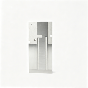




Injection Mold Sprue and Gate Components, Planned From the Drawing
A disciplined review aligns mold feed-system component requirements with feasible manufacturing, inspection, and controlled revisions before production commitments.
Drawing-Led DFM Review
We review drawings, models, datums, mating context, and critical features to identify manufacturability questions before quotation and production planning.
Process Route Selection
CNC machining, EDM, grinding, and fitting are considered against geometry, tool access, surface requirements, and required feature relationships.
Critical Dimension Planning
Critical-to-quality dimensions are identified with datum strategy, machining allowance, and measurement considerations appropriate to the approved drawing.
EDM and Grinding Strategy
Electrode needs, wire paths, burn locations, grinding stock, and heat-treatment sequence are reviewed where feed-system geometry requires them.
Inspection Aligned to Requirements
Inspection planning focuses on specified dimensions, surfaces, and reporting expectations so final documentation matches the verified order requirements.
Revision-Controlled Coordination
Drawing revisions, open technical questions, and delivery information remain visible throughout project coordination to reduce avoidable production ambiguity.
Injection Mold Sprue and Gate Components
Drawing-driven component families for runner, gate, core, ejection, and tooling requirements, planned around critical dimensions, process access, and inspection needs.

CNC Machining Services
Precision CNC machining services for drawing-based custom parts, injection mold components, and tooling details. Process planning considers material, datums, critical dimensions, tool access, machining allowances, surface requirements, quantity, and the inspection evidence required before production begins.
Upload a Drawing
CNC Milling
Custom CNC milling services support prismatic, pocketed, contoured, and multi-feature components used in molds and tooling. Drawing review addresses clamping, cutter reach, internal radii, datum transfer, remaining stock for EDM or grinding, and dimensional priorities.
Upload a Drawing
CNC Turning
Precision CNC turning services support rotational components such as pins, bushings, sleeves, nozzles, guide elements, and custom shafts. Reviews focus on concentricity, runout, thread details, shoulder geometry, material condition, and any secondary milling, EDM, grinding, or inspection needs.
Upload a Drawing
5-Axis Machining
5-axis CNC machining helps access angled, contoured, and compound features while reducing unnecessary setups where the geometry supports it. SUUXIANG evaluates tool reach, fixture strategy, datum control, surface requirements, and whether EDM or grinding remains necessary for critical features.
Upload a Drawing
Swiss & Micro Machining
Swiss machining and micro machining support small, elongated, and detail-intensive parts where feature stability and handling matter. Provide drawings with diameters, lengths, tolerances, material, quantity, surface requirements, and any mating-component context for a practical manufacturing review.
Upload a Drawing
Wire & Sinker EDM
Wire EDM services and sinker EDM services address profiles, narrow slots, sharp internal geometry, hardened materials, and features with limited cutter access. Process selection considers wire path, start-hole access, electrode design, EDM allowance, surface expectations, and subsequent fitting or inspection requirements.
Upload a Drawing
Precision Grinding
Precision surface and profile grinding supports controlled flatness, parallelism, profile form, and final stock removal on applicable components. Grinding plans account for heat-treatment sequence, grinding allowance, datum strategy, material condition, and the inspection method for critical dimensions.
Upload a Drawing
Mold Core & Cavity Inserts
Precision mold core inserts and mold cavity inserts are configured from the molding requirement, part geometry, material specification, cooling or venting needs, and critical surfaces. Manufacturing may combine CNC machining, EDM, grinding, fitting, and documented inspection according to the approved drawing revision.
Upload a Drawing
Ejector & Ejection Components
Ejector pins, sleeves, and ejection components are reviewed for stroke, guidance, clearance, wear conditions, surface requirements, and interaction with the molded part. Drawings should identify critical diameters, datum surfaces, heat treatment requirements, and any fitting expectations.
Upload a Drawing
Core Pins, Guide & Locating Components
Core pins, guide pins, and locating components require clear control of functional diameters, shoulder positions, concentricity, mating fits, and wear-related surfaces. SUUXIANG reviews the mating context, material and treatment requirements, manufacturing route, and inspection points before commitment.
Upload a Drawing
Slides, Lifters, Gates & Mold Accessories
Mold slides, lifters, gates, and accessories are supplied as configurable drawing-based components for movement, guidance, feed, and supporting mold functions. Review should cover travel or interface geometry, gate location, material condition, machining access, EDM needs, fitting requirements, and critical inspection features.
Upload a Drawing
Connector Mold Components
Precision connector mold components support detail-rich tooling for connector features, cavities, pins, inserts, and related locating elements. Manufacturing planning considers fine geometry, material, EDM or micro-machining requirements, surface condition, mating relationships, critical dimensions, and revision-controlled inspection.
Upload a Drawing
Stamping Die Components
Precision stamping die components are manufactured from approved drawings for cutting, forming, guiding, and locating functions. A useful review identifies material and heat treatment, working edges, clearance-sensitive geometry, grinding stock, EDM requirements, datum references, and inspection expectations.
Upload a Drawing
Injection, MIM, CIM & Overmolding Tooling
Injection, MIM, CIM, and overmolding tooling components are evaluated within verified production scope using the application’s geometry, material behavior, interface details, and quality requirements. Drawing review addresses core and cavity strategy, gates, vents, inserts, access limitations, and fitting needs.
Upload a Drawing
Machining Materials
CNC machining materials are selected against drawing requirements, functional load, corrosion exposure, heat-treatment needs, dimensional stability, and downstream finishing. Specify the material grade or approved equivalent, condition, certification needs, and any restrictions affecting the planned machining route.
Upload a Drawing
Surface Finishes & Heat Treatment
Surface finishing and heat treatment are planned as controlled requirements, not assumed defaults. Define finish type, roughness or appearance criteria, treatment specification, hardness or depth where applicable, masking needs, dimensional allowances, and how post-process dimensions will be verified.
Upload a Drawing
Quality, Metrology & Documentation
Precision inspection, metrology, and quality documentation are aligned to the drawing and agreed inspection plan. Identify critical dimensions, datum references, measurement method, report format, traceability expectations, revision status, and any customer-specific documentation needed with the order.
Upload a Drawing
Prototyping & Low-Volume Production
Rapid prototyping and low-volume manufacturing support drawing-based parts when teams need to validate fit, function, tooling details, or controlled small-batch demand. Submit quantity, material, critical dimensions, surface requirements, delivery target, and inspection needs for a feasible process review.
Upload a DrawingMaterials for Injection Mold Sprue and Gate Components

P20 Tool Steel
A practical pre-hardened choice for sprue bushings, gate inserts, and general mold components where balanced machinability and service durability are required. Final hardness, surface finish, and polishing requirements should follow the drawing.

H13 Tool Steel
Often considered for components exposed to repeated thermal cycling, including gate-area inserts and high-temperature tooling details. Its heat-treatment condition, EDM sequence, and grinding allowance should be defined against the intended molding application.

420 Stainless Steel
A corrosion-resistant option for mold components used with moisture-sensitive processing environments or corrosive resin systems. Specify the required hardness, polish level, and corrosion expectations so machining and heat-treatment planning can be reviewed.

S7 Tool Steel
A tough tool-steel option for wear-prone or impact-sensitive mold details where resistance to chipping matters. Material condition, hardness target, and mating-part clearance should be checked before CNC, EDM, and finishing operations begin.

Beryllium Copper
Used selectively for inserts requiring improved heat transfer near localized molding features. Because geometry, joining method, handling requirements, and wear conditions affect suitability, confirm the application and drawing callouts during DFM review.
Supported Processes for Injection Mold Sprue and Gate Components


Wire EDM
Wire EDM produces precise through-features, narrow slots, and complex profile details where conventional cutting access is limited. The wire path and finishing passes are planned around geometry, corner conditions, and drawing requirements.

Sinker EDM
Sinker EDM forms deep, detailed, or difficult-to-reach cavity features using electrodes matched to the required geometry. Electrode strategy, spark allowance, and surface expectations are considered before machining begins.

Precision Grinding
Precision grinding controls flatness, parallelism, and critical fitted surfaces after the appropriate material and heat-treatment sequence. Grinding stock and datum references are defined to protect functional dimensions and assembly relationships.

Fitting and Inspection
Fitting confirms intended relationships between mating components, while inspection follows the agreed critical-dimension plan. Results, revision status, and required reporting are aligned with the order before shipment coordination.
Accessories for Injection Mold Sprue and Gate Components

Guide Locating Elements
Guide pins, bushings, locating blocks, and alignment features help maintain repeatable mold-half positioning. Provide mating dimensions, datum references, material requirements, and expected fit conditions for coordinated machining and inspection.

Ejection Interface Parts
Ejector pins, sleeves, return elements, and related interfaces can be specified alongside feed-system components. Identify stroke conditions, clearance priorities, contact surfaces, and critical diameters to support practical fit and revision control.


Slides and Lifters
Slides, lifters, and associated locating features may be coordinated when gate placement or undercut geometry affects mold motion. Define travel, interface geometry, wear surfaces, lubrication constraints, and assembly relationships for DFM review.

Identification Packaging
Part marking, revision identification, protective packaging, and inspection-document requirements can be incorporated when specified. State labeling format, corrosion-protection needs, packing quantity, traceability expectations, and any shipment handling constraints.
Injection Mold Sprue and Gate Components at SUUXIANG
SUUXIANG is the sole public-facing precision-manufacturing brand of Dongguan SuuXiang Precision Mold Co., Ltd., established in 2010 in Chang’an Town, Dongguan, Guangdong, China. Founded by XiaoCheng Huang, the company helps global engineering and sourcing teams turn drawings and specifications into inspected precision mold components, connector tooling, and custom machined parts.
For injection mold sprue and gate components, our workflow begins with drawing review and DFM discussion. We assess critical dimensions, datums, material and heat-treatment requirements, machining access, EDM or grinding needs, surface priorities, inspection expectations, and revision status before production commitments are made.
Our difference is disciplined coordination across CNC milling and turning, multi-axis machining, EDM, precision grinding, fitting, and inspection. Rather than treating components as an undifferentiated catalogue, SUUXIANG plans the process route around the drawing, records the agreed quality requirements, and keeps manufacturing and delivery information traceable.

Injection Mold Sprue and Gate Components: Critical Feature Control
Drawing Review and Datums
SUUXIANG reviews the 2D drawing, model, mating conditions, and critical dimensions before confirming a process route. Datum references, tolerance relationships, tool access, and surface priorities are clarified early so the injection mold sprue and gate components can be planned against measurable requirements.
- Identify critical-to-quality dimensions and functional mating features
- Confirm datum strategy across machining, EDM, grinding, and inspection
- Review wall transitions, shut-offs, and access constraints
- Keep drawing revisions visible before production release

EDM Strategy for Fine Geometry
Where conventional cutting access is limited, EDM planning should account for feature geometry, electrode approach, wire path, finishing allowance, and the downstream inspection method. SUUXIANG evaluates these inputs with the drawing to select a practical route for detailed sprue, gate, and insert features.
- Assess wire-EDM access for slots, profiles, and sharp internal geometry
- Plan electrode direction and clearance for sinker-EDM features
- Define stock remaining for subsequent finishing operations
- Align EDM strategy with functional surfaces and dimensional priorities

Grinding and Fitting Control
Precision mold interfaces often depend on controlled grinding stock and fitting sequence, not machining dimensions alone. SUUXIANG coordinates milling, EDM, grinding, and fitting around the specified datums so contact surfaces, locating features, and assembly relationships can be evaluated in the correct order.
- Reserve appropriate allowance before finish grinding
- Sequence operations around hardened or heat-treated conditions
- Check mating interfaces, locating surfaces, and movement-related features
- Escalate drawing ambiguities that could affect fit or assembly

Inspection Records That Match
Inspection planning begins with the order requirements rather than a generic checklist. For injection mold sprue and gate components, SUUXIANG aligns the inspection method, reporting expectations, critical dimensions, and revision status with the approved drawing and agreed project scope before final documentation is issued.
- Link inspection points to drawing callouts and datums
- Confirm reporting needs before production begins
- Verify material, heat-treatment, or surface requirements when specified
- Maintain traceable revision and delivery information

Why Choose SUUXIANG for Injection Mold Sprue and Gate Components
Compare SUUXIANG’s drawing-led workflow with typical quote-only sourcing practices; supplier processes and evidence vary by project.
← Swipe left or right to view →
Injection Mold Sprue and Gate Components: Drawing to Inspected Parts
A controlled project path that aligns DFM, process planning, critical-dimension verification, documentation, and delivery coordination before production commitments are made.
RFQ and Drawing Review
Share 2D drawings, 3D models, material, quantity, quality expectations, and delivery target so the project team can clarify requirements and application context.
DFM and Process Planning
Review critical dimensions, datums, tool access, surface requirements, heat-treatment sequence, EDM needs, grinding stock, and inspection methods before quotation or release.
Material and Production Release
Confirm the approved drawing revision, material specification, process route, and project records before machining begins, keeping changes visible throughout the manufacturing workflow.
Machining EDM and Grinding
Manufacture components through the appropriate CNC, multi-axis, EDM, precision grinding, and fitting operations, with each route selected for the specified geometry and features.
Inspection Packing and Coordination
Verify agreed dimensions using the planned inspection approach, prepare order-matched documentation, protect finished parts for shipment, and coordinate delivery information with the customer.
How to Submit Injection Mold Sprue and Gate Components
Provide complete engineering inputs so SUUXIANG can review manufacturability, align inspection expectations, and coordinate a responsible quotation path.
Send Your Drawing Package
Upload the 2D drawing and available 3D model for injection mold sprue and gate components, including revision level, datums, critical dimensions, and surface requirements.
Define Production Requirements
Specify material, heat treatment, quantity, application context, mating components, quality documentation, and target delivery date so the manufacturing route can be assessed.
Review DFM Feedback
Discuss machining access, EDM or grinding needs, tolerance stack, inspection method, and any design risks before quotation, sampling, or production commitments are confirmed.
Confirm the Production Plan
Align the approved drawing revision, process route, inspection plan, delivery coordination, and reporting requirements before SUUXIANG begins controlled manufacturing of your components.
Certificates and Quality Documentation

Public Customer Testimonial Status
Approved customer testimonial and case evidence are not currently available for public publication. SUUXIANG protects confidential drawings, applications, and performance details until written approval is confirmed.
Customer drawings, applications, and performance details remain confidential unless written approval permits public use.
No public case study is published without verified evidence and written customer approval.
Buyer’s Guide to Injection Mold Sprue and Gate Components
Practical RFQ, quality, and production-planning answers for drawing-based tooling components.
What should I include in an RFQ for injection mold sprue and gate components?
Can SUUXIANG quote low-volume injection mold sprue and gate components?
How are tolerances assessed for injection mold sprue and gate components?
Which materials can be considered for sprue and gate tooling parts?
Can I request first-article or dimensional inspection reports?
How should I plan lead time for custom mold feed-system components?
How are drawing revisions and IP handled during a quotation project?
What information is needed for shipping and payment planning?
Buyer’s Guide to injection mold sprue and gate components
Use this decision framework to specify feed-system components, compare supplier capabilities, control quality and cost, and avoid design, sourcing, and launch mistakes that compromise molded-part performance.
1. What Are Injection Mold Sprue and Gate Components?
Three feed-system stages carry melt from the molding-machine nozzle: the sprue, runner, and gate. The sprue bushing is the hardened mold insert that receives the nozzle and forms the primary entry passage; runners distribute melt toward one or more cavities, while the gate is the controlled restriction at cavity entry. https://www.wevolver.com/article/what-are-injection-mold-sprues-runners-and-gates
One term can describe two different things: a physical sprue bushing or machined runner channel, and the solidified plastic sprue-and-runner network ejected with a cold-runner shot. RFQs for injection mold sprue and gate components should state which is required, because the latter is material residue to trim or regrind, not a supplied steel component.
At the gate, section size, land, location, and freeze-off timing govern how the cavity fills and how long packing pressure remains effective. Those choices influence short-shot or sink risk, the visible gate witness, cooling and cycle time, and cold-runner material consumption; they therefore belong in drawing review and DFM before steel is released.
2. Evolution of Injection Mold Feed Systems
1 basic cold-runner layout carries melt through an unheated sprue and runner, then ejects that solidified network with the parts. Its simple steel, accessible maintenance, and lower initial cost suit prototypes and low-volume programs, but trimming and regrind planning add resin waste and gate-mark risk. Source: https://www.wevolver.com/article/what-are-injection-mold-sprues-runners-and-gates
2 balanced-runner approaches made multi-cavity filling more repeatable by equalizing flow length or deliberately tuning branch resistance. They reduce cavity-to-cavity variation, yet require stronger flow analysis, tighter machining control, and disciplined process windows than a simple layout.
3 insulated runners retain a molten core within a controlled runner, while heated manifolds and valve gates remove most cold-runner scrap and improve gate-location options. Hot-runner tooling raises upfront complexity, temperature-control and maintenance demands; valve gating adds timing control and can improve cosmetics, making these routes more defensible for sustained production than short prototype runs.
3. Types of Injection Mold Sprue and Gate Components
Two feed-system decisions drive early DFM: runner temperature control and the gate’s location on the part. Select injection mold sprue and gate components around fill path, witness-mark tolerance, and automatic versus manual separation.
| Gate | Typical Position | De-Gating And Best Fit | Cosmetic Impact |
|---|---|---|---|
| Sprue | Center or thick section | Manual; single-cavity, direct feed | Large witness |
| Edge | Parting-line edge | Manual; general parts | Visible edge mark |
| Fan | Wide edge | Manual; wide flat parts | Broad witness |
| Tab | Edge with sacrificial tab | Manual; stress-sensitive fills | Tab removed |
| Pin | Core-side point | Automatic; small parts | Small point vestige |
| Tunnel | Below parting line | Automatic; hidden edge feed | Usually concealed |
| Cashew | Curved sub-surface | Automatic; recessed location | Concealed, harder to tool |
| Diaphragm | Circular core | Manual; annular parts | Uniform ring mark |
| Valve | Hot-runner nozzle | Controlled shutoff; high-volume | Minimal witness |
| Hot tip | Hot-runner point | Direct feed; multi-cavity | Small tip mark |
Sprue Bushings And Runners
A sprue bushing seats at the nozzle interface and feeds a cold runner or cavity directly. Cold runners eject with the part and require separation; hot runners keep melt heated, reducing runner scrap but adding controls and maintenance.
Gate Selection Matrix
Ten common gates differ primarily in access, vestige, and separation behavior.
Gate Location Review
Gate placement should follow a flow-length, weld-line, packing, and appearance review before steel release. Brittle resins and visible Class-A surfaces require particular attention to gate break-off and witness location.
4. Materials for Injection Mold Sprue and Gate Components
Material selection sets the wear, thermal, polishing, and maintenance limits of injection mold sprue and gate components. Specify the resin, service temperature, projected shot count, and repair strategy before steel is released.
| Material Route | Use Case | Key Trade-Off |
|---|---|---|
| Tool steel | General wear service | Hardness versus repairability |
| Stainless grade | Corrosive resin exposure | Corrosion resistance versus polish route |
| Beryllium-copper insert | Localized cooling | Conductivity versus wear protection |
Match Steel To Resin
Glass-filled resins abrade gate land, runner, and nozzle-contact surfaces; select a suitable hardened tool steel and leave grinding or EDM finishing allowance.
Corrosive polymers require stainless or corrosion-resistant grades where condensate and resin by-products can attack feed surfaces.
Use Conductive Inserts Carefully
Beryllium-copper inserts can remove heat from localized gate areas, but their fit, support, wear exposure, and safety controls need review.
High polish requirements favor a material and heat-treatment route that can be finished without unstable texture or edge damage.
Document The Material Route
Mill certificates, heat-treatment records, hardness requirements, and incoming identification should follow the component through inspection and revision control.
Resin selection also drives feed-system geometry, gate size, thermal control, and the treatment decision; verify all against the drawing and molding conditions.
5. Customizing Injection Mold Sprue and Gate Components
A drawing review should convert molded-part requirements into a feed-system plan before steel is cut. For injection mold sprue and gate components, SUUXIANG should confirm CTQs, resin, cavity count, machine nozzle data, cosmetic zones, and inspection expectations.
| Design Input | Decision To Lock | Part Risk Controlled |
|---|---|---|
| Cosmetic zone | Gate location and vestige | Gate mark |
| Cavity count | Runner balance and diameter | Fill variation |
| Nozzle data | Sprue taper and interface | Leakage or sticking |
| Fiber-filled resin | Gate direction | Orientation and warpage |
Set The Gate Strategy

First, locate the gate against cosmetic surfaces, knit-line tolerance, packing direction, and expected fiber orientation. Gate position and size affect filling pressure, weld lines, warpage, and the visible gate mark.
Second, define gate thickness, width, and land length from wall thickness, resin behavior, and freeze-off requirement. Record the approved gate witness and any allowable trimming method on the drawing.
- Identify appearance-critical faces
- Specify permitted gate-mark area
- Provide resin and fiber-fill grade
Balance The Feed Path
For 2 or more cavities, equal flow paths or deliberately sized runners should be reviewed against cavity filling behavior. Runner diameter, branch geometry, and pressure loss must be assessed with the selected resin and shot size.
A 1.5° per-side sprue draft is a common starting reference for release, but nozzle interface, bushing design, cooling, and cold-slug control require project-specific confirmation. Source: https://www.plasticmoulds.net/spruesrunners-and-gates-of-plastic-mold
Choose De-Gating And Hot Runner
Cold-runner tooling needs a documented choice between manual trimming and automatic de-gating, including allowable vestige and break risk. Tunnel and curved gates may self-degate but demand suitable geometry and material behavior.
Hot-runner layouts require nozzle pitch, gate style, thermal zones, access for maintenance, and startup expectations in the RFQ. Valve gating can control filling timing, yet adds tooling complexity and validation work.
6. Quality Elements in Sprue and Gate Construction
Quality review of injection mold sprue and gate components starts at the interfaces, not after trial. Drawing-defined datums, inspection methods, and mating-part revision status should govern acceptance.
Alignment And Fits
Concentricity between nozzle seat, sprue bore, and runner centerline prevents shear, leakage, and uneven cavity filling.
Matched locating diameters and hardened contact faces must seat without rocking; poor fit can cause flash, sticking, or imbalance.
Flow And Release Surfaces
A continuous polished flow path and specified draft support clean sprue release and repeatable pressure loss.
Gate land, edge break, and transition radii require defined condition criteria; damaged edges can create short shots or inconsistent gate vestige.
Thermal And Service Checks
Cooling circuits must maintain wall separation, sealing integrity, and accessible connections before steel release.
Vents require protected depth control and cleaning access; blocked vents promote burns, short shots, and unstable fill. Interchangeable inserts need documented datum and revision checks.
7. Choosing an Injection Mold Sprue and Gate Components Supplier
A 2D drawing and 3D model should drive supplier selection, not a catalog claim. For injection mold sprue and gate components, compare evidence before releasing steel.
DFM And Process Route
DFM review should identify datums, gate geometry, steel condition, tool access, EDM electrodes or wire paths, and grinding stock. Mold-flow input should be available when fill balance, weld lines, pressure, or gate freeze-off affects the decision.
Evidence Before Production
Material certificates, revision-controlled drawings, first-article dimensional reports, and defined inspection methods should match the purchase order. Trial-shot support and hot-runner sourcing require a clear responsibility boundary, component specification, and feedback path.
Program Control And Support
Weekly communication should expose open technical questions, approved changes, inspection status, and realistic lead-time risks. Ask for relevant connector, precision-mold, and low-volume experience, plus a documented route for replacement or spare components.
8. Common Buyer Mistakes With Sprue and Gate Components
Eight recurring RFQ errors turn a low-cost feed-system choice into visible defects, scrap, rework, or launch delay. Review injection mold sprue and gate components against the molded part, not the tool alone.
Tooling Cost Alone
A low-cost edge gate can require trimming and leave a witness mark. Define gate location, allowable mark, and de-gating method before quoting.
Missing Material Inputs
Resin grade, filler level, color, and cosmetic zones affect flow and appearance. Provide these requirements with the drawing so DFM can assess fill path, shear, and venting.
Runner And Layout Errors
Cold-runner volume becomes material handling and regrind cost on every shot. Compare runner-to-part mass and balance multicavity flow before steel release.
Unequal flow paths can create cavity-to-cavity variation and longer process development. Require a balanced layout or documented flow-analysis rationale.
Release And Acceptance Gaps
Premature steel approval can lock in inaccessible gates, worn shutoffs, or impractical maintenance. Hold a DFM review covering tool access, replacement strategy, and service clearances.
Undefined acceptance criteria invite disagreement after sampling. Specify critical dimensions, gate vestige limits, cosmetic zones, inspection method, sample quantity, and revision-controlled approval.
9. Launching Injection Mold Sprue and Gate Components
A controlled launch converts the part drawing, resin specification, annual volume, and acceptance criteria into accountable manufacturing decisions. For injection mold sprue and gate components, approval points must precede irreversible steel cutting.
Define The Engineering Package
First, submit the 2D drawing, 3D model, resin grade, shrinkage data, part function, cosmetic zones, and mating context. SUUXIANG can use these inputs to identify CTQ dimensions, datums, surface requirements, and inspection evidence needed for quotation.
Approve Feed-System Decisions
Before quotation release, review proposed gate location, gate-removal method, runner concept, tool access, cooling implications, and likely weld-line or witness-mark risks. When geometry, resin behavior, or cavity balance creates uncertainty, require flow analysis before design approval and steel cutting.
Validate Trials And Release
After component inspection, trial molding should confirm fill, packing response, dimensions, cosmetic condition, and gate vestige against the agreed criteria. Document the approved process window, record revisions, close deviations, and release production only after buyer sign-off on samples and inspection results.
10. Injection Mold Sprue and Gate Components Pricing
Three representative scopes make pricing discussions more useful than a single unit-cost request. The matrix separates manufactured components from mold-system work; actual pricing follows the released drawing, quantity, material specification, and inspection plan.
Seven quote variables commonly change cost: steel grade, tight tolerances, surface finish, heat treatment, cavity count, runner geometry, and revision maturity. State target dates, critical dimensions, report requirements, mating context, and whether hot-runner hardware is customer-supplied before SUUXIANG confirms a process route.
| Scope | Typical cost drivers | Indicative planning lead time | Validation scope |
|---|---|---|---|
| Component-only | Material, EDM or grinding, finish, heat treatment, inspection | 1–3 weeks | Dimensional checks to agreed plan |
| Cold-runner features | Cavity count, balanced runners, gate geometry, fitting, revisions | 3–6 weeks | Assembly checks and agreed tryout support |
| Hot-runner integration | Manifold/nozzle hardware, interfaces, thermal design ownership, cavity count | 6–10+ weeks | Interface verification; molding validation quoted separately |
Upload Injection Mold Sprue and Gate Components Drawings
Share drawings, material, quantity, critical dimensions, inspection needs, and delivery target for a project-specific DFM discussion and quotation.