
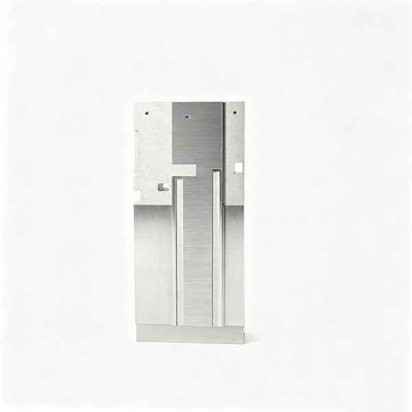
Core and Cavity Insert for Drawing-Based RFQ
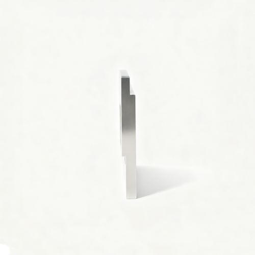
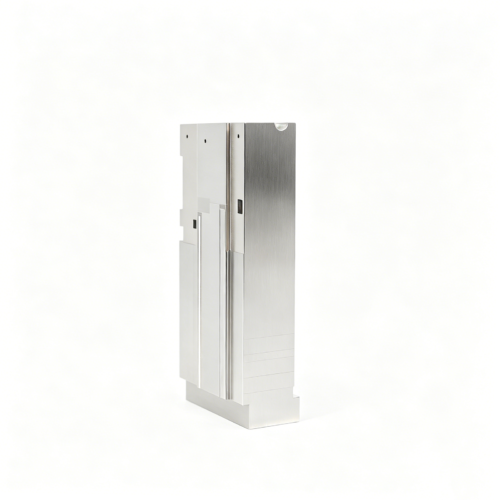
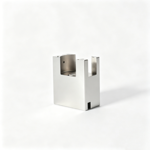
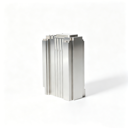
This custom connector cavity block is intended for projects where the block body, cavity form, mounting faces and inspection datums must be defined together. The visually reviewed image from the same-company original product gallery 71843 is useful as a shape reference only. It does not establish dimensions, materials, tolerances, cavity purpose or manufacturing history. The approved customer drawing and engineering review remain the controlling basis for quotation and production planning.
Define the Block Reference Scheme
The first RFQ decision is which block faces locate the assembly and which faces are used for inspection. A cavity can meet local dimensions while still missing its position relative to block datums, mounting holes, seating faces or a mating insert. Please identify primary, secondary and tertiary references, along with any functional face that must remain uninterrupted. The drawing package should distinguish locating surfaces from non-functional stock, show orientation, and state whether dimensions originate from the outside block, a mounting pattern or the cavity centerline. If several cavities or inserts share a reference, the relationship should be shown explicitly rather than inferred from a photograph.
Separate Form, Access and Allowance Decisions
Cavity details often require different access strategies within one block. Deep pockets, narrow transitions, corner radii, shutoff edges and protected steps may need separate electrode access, cutting access or polishing allowance. A quotation should therefore identify inaccessible regions, minimum tool approach, electrode split lines where relevant, and areas where finishing stock is intentional. Rough cavity work can be planned with an agreed allowance, while seating faces and datum surfaces may require a controlled finishing sequence. The required corner condition should be stated by radius, blend, sharp-edge limit or another drawing-defined description. Transitions should not be left to visual interpretation.
Conditional Process Route
After reference faces are established, a conditional route may include block preparation, rough cavity removal with the approved allowance, and a review of whether EDM is warranted for inaccessible form. Cutting, grinding, EDM and hand finishing are selected only after feature scale, access, material specification and surface requirements are confirmed. Seating faces can be finished after the cavity strategy is agreed so that the insert remains related to its mounting condition. Functional edges should be protected during polishing and deburring. The final route may change when the revision changes, when a shutoff is redefined, or when inspection access reveals a different control requirement.
Drawing Package for a Reliable RFQ
For a useful quotation, provide the latest controlled drawing, three-dimensional model when available, revision identifier, quantity, intended application context, and a marked image showing orientation. Include cavity depth, local radii, shutoff regions, seating heights, mounting features, datum hierarchy, edge treatment and any surfaces excluded from polishing. If a feature must be produced or inspected from a separate electrode, identify it as such or describe the required access. Clarify whether the quoted part is a rough insert, a finished insert or a component prepared for later fitting. Open questions should be listed against drawing zones rather than resolved through assumptions.
Inspection Strategy and Acceptance Language
Inspection should tie cavity form and location to the mounting datums selected during engineering review. Depending on actual feature scale, checks may include dimensional measurement, datum-based coordinate verification, profile comparison, gauge evaluation or controlled visual review. The inspection condition should state how the block is supported and how seating faces are established. Surface criteria need separate language: visual or comparative requirements should identify the approved reference, viewing condition and acceptable transition. Polishing must not erase an edge or alter a shutoff beyond the drawing requirement. No quality metric, tolerance, certification or performance claim is implied until the customer specification defines it.
Revision Control and Drawing-Based Communication
RFQ communication should preserve the exact revision used for every decision. A practical inquiry can identify SKU SUUXIANG-SAMPLE-007, attach the drawing and model, list the primary datum faces, mark cavity regions requiring special access, and ask for confirmation of the proposed allowance and inspection method. If the cavity is updated, note whether the change affects the block outline, seating faces, electrode strategy, polishing boundary or measurement program. Written approval should close those questions before work begins. This process helps separate confirmed requirements from provisional process ideas and keeps the quotation aligned with the intended insert assembly.
Part-Specific FAQs
Which cavity details should be highlighted for separate access review?
Mark deep or enclosed forms, narrow transitions, small corner radii, shutoff edges and any region that cannot be reached by the proposed cutting or polishing direction. Also identify where an electrode or finishing tool may need an independent approach.
Can the block be quoted from the image alone?
No. The image can support a preliminary visual conversation, but block datums, cavity location, allowances, edge conditions and inspection requirements must come from the approved drawing and engineering review.
Send the Controlled Drawing for Review
Share the current drawing, model, revision and datum questions for a drawing-based assessment of this custom cavity block.
Reviews
There are no reviews yet.