
MIM Tooling Components, From Drawing to Inspection
SUUXIANG reviews critical dimensions, DFM, EDM and grinding requirements for MIM tooling components before production planning.
Featured Components for MIM Tooling Development


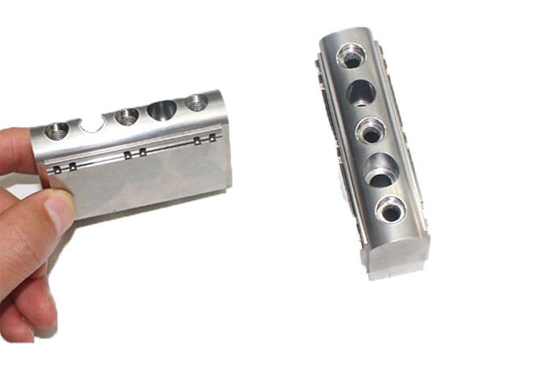

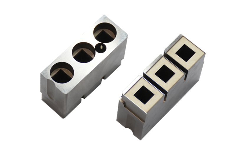

Related Drawing-Based Tooling Components





MIM Tooling Components: Engineering Advantages
A disciplined workflow for translating critical tooling requirements into planned machining, inspection, and revision-controlled delivery.
Drawing-Led DFM Review
Each RFQ begins with a drawing-focused review of datums, tool access, feature relationships, and manufacturability questions before process commitments are discussed.
Critical Dimension Planning
Critical dimensions, surface requirements, tolerance stack concerns, and inspection priorities are identified early to align the manufacturing route with functional intent.
Integrated Machining Routes
CNC milling, turning, multi-axis machining, EDM, and fitting are considered together, helping select practical routes for complex tooling features.
EDM and Grinding Strategy
Electrode needs, wire paths, machining allowances, and grinding stock are reviewed to support accessible geometry and controlled finishing operations.
Inspection and Revision Visibility
Inspection methods, documentation expectations, drawing revisions, and delivery information remain visible throughout coordination, supporting clearer decisions before final acceptance.
MIM Tooling and Precision Component Families
Drawing-driven process routes for configurable tooling components, custom machined parts, and inspection-defined production requirements.

CNC Machining Services
Precision CNC machining services for drawing-based parts requiring coordinated milling, turning, EDM, grinding, fitting, and inspection. Process selection begins with critical dimensions, material condition, datums, tool access, and the agreed inspection method.
Upload a Drawing
CNC Milling
Custom CNC milling services for prismatic parts, inserts, plates, and complex machined features. Drawing review addresses machining access, workholding, corner conditions, datum relationships, stock allowance, and surface requirements before production planning.
Upload a Drawing
CNC Turning
Precision CNC turning services for rotational parts such as pins, sleeves, bushings, shafts, and locating features. The process route considers concentricity, runout, diameter tolerances, thread requirements, material condition, and any downstream grinding or heat treatment.
Upload a Drawing
5-Axis Machining
5-axis CNC machining supports multi-face geometry, angled features, and difficult-to-access contours with fewer setups where the part geometry and inspection plan support it. Tool reach, fixturing, collision clearance, datum transfer, and finishing requirements are reviewed from the drawing.
Upload a Drawing
Swiss & Micro Machining
Swiss machining and micro machining support small-diameter pins, sleeves, shafts, and miniature connector-related features. Feasibility depends on geometry, material, length-to-diameter ratio, tolerance priorities, burr control, and measurement access for the specified features.
Upload a Drawing
Wire & Sinker EDM
Wire EDM services and sinker EDM services address hardened materials, sharp internal profiles, narrow slots, fine details, and features inaccessible to conventional tools. Planning considers wire path or electrode strategy, flushing, corner requirements, recast-layer expectations, and finishing allowance.
Upload a Drawing
Precision Grinding
Precision surface and profile grinding is used where flatness, parallelism, profile control, or post-heat-treatment dimensional correction is required. The drawing review identifies grinding stock, datum sequence, material condition, surface requirements, and practical inspection points.
Upload a Drawing
Mold Core & Cavity Inserts
Precision mold core and cavity inserts are manufactured from customer drawings for injection-related tooling applications. Process planning considers parting geometry, cooling or venting features, shutoffs, material and heat treatment, EDM access, polishing requirements, and critical mating dimensions.
Upload a Drawing
Ejector & Ejection Components
Ejector pins, sleeves, and ejection components are configured to the tool design, motion requirements, material specification, and mating conditions. Review focuses on fit, clearance, straightness, head geometry, surface condition, wear considerations, and inspection requirements.
Upload a Drawing
Core Pins, Guide & Locating Components
Core pins, guide pins, bushings, and locating components are produced to defined datum and fit relationships. Engineering review addresses alignment function, contact surfaces, hardness sequence, clearance, concentricity, replaceability, and dimensional controls that affect mold assembly.
Upload a Drawing
Slides, Lifters, Gates & Mold Accessories
Mold slides, lifters, gates, and accessories are made as drawing-defined tooling components rather than stock assumptions. Review covers travel and interference conditions, sliding interfaces, wear surfaces, gating geometry, material treatment, assembly datums, and fitting requirements.
Upload a Drawing
Connector Mold Components
Precision connector mold components support tooling for connector housings, terminals, and related molded features. Manufacturing planning considers fine pitch geometry, pin and cavity alignment, mating interfaces, EDM strategy, material condition, wear areas, and inspection access.
Upload a Drawing
Stamping Die Components
Precision stamping die components are produced for drawing-specific forming, blanking, piercing, and guiding functions. The required route depends on material, heat treatment, cutting-edge condition, clearance, grinding allowance, wire-EDM profile needs, and assembly relationships.
Upload a Drawing
Injection Mold Components, MIM, CIM & Overmolding Tooling
Injection, MIM, CIM, and overmolding tooling components are evaluated within verified production scope. Review begins with the molding process, feed or gating needs, shrinkage and venting considerations, insert interfaces, material condition, critical dimensions, and maintenance requirements.
Upload a Drawing
Machining Materials
CNC machining materials are selected from the drawing, application, heat-treatment requirement, and inspection criteria. Buyers should identify the specified grade, material condition, required certificates, corrosion or wear demands, and any restrictions affecting machining or EDM.
Upload a Drawing
Surface Finishes & Heat Treatment
Surface finishing and heat treatment are planned as part of the dimensional route, not added after machining. Requirements may affect stock allowance, distortion risk, surface texture, corrosion resistance, wear behavior, masking, final dimensions, and inspection timing.
Upload a Drawing
Quality, Metrology & Documentation
Precision inspection, metrology, and quality documentation are defined against the order and agreed inspection plan. Useful RFQs identify critical dimensions, datums, measurement method expectations, reporting format, material evidence, revision status, and traceability needs.
Upload a Drawing
Prototyping & Low-Volume Production
Rapid prototyping and low-volume manufacturing support drawing-based evaluation, tooling development, and controlled small-batch requirements. Quote review confirms quantity, material, revision maturity, critical features, inspection scope, delivery target, and whether process choices remain practical at volume.
Upload a DrawingMaterials for MIM Tooling Components

H13 Tool Steel
A practical choice for tooling areas exposed to repeated thermal cycling and demanding service conditions. Machining, EDM strategy, heat treatment and final grinding stock should be planned together against the drawing’s critical dimensions.

S7 Tool Steel
Often considered where impact resistance matters in MIM tooling components, including features subject to repeated loading. Confirm required hardness, surface condition, geometry and post-heat-treatment finishing allowance during the technical review.

A2 Tool Steel
Suitable for precision tooling features where dimensional stability, wear behavior and controlled hardening require evaluation. SUUXIANG reviews section thickness, EDM access, grinding requirements and inspection datums before selecting a process route.

Hardened Stainless Steel
Used when corrosion resistance and durable tooling performance must be balanced with machinability and finishing needs. Material grade, hardness condition, surface requirement and mating-part context should be supplied with the RFQ.

Pre-Hardened Tool Steel
Useful for prototype or lower-volume tooling components when a heat-treatment stage may not suit the schedule or geometry. Drawing review should confirm expected service conditions, tolerances, wear areas and any subsequent EDM or grinding work.
Manufacturing Processes for MIM Tooling Components

CNC Milling
CNC milling develops cavity, core, plate, and feature geometry with controlled tool access. It supports efficient stock removal and finished surfaces where cutter reach, datum strategy, and remaining machining allowance are reviewed first.

CNC Turning
CNC turning produces rotational MIM tooling components such as pins, bushings, sleeves, and locating features. Concentricity, bearing surfaces, thread requirements, and datum relationships should be defined on the drawing before process planning.


Wire EDM
Wire EDM cuts precise profiles, narrow slots, and intricate through-features after considering wire path, start-hole access, and datum references. It is useful where conventional cutters cannot achieve the required internal geometry cleanly.

Sinker EDM
Sinker EDM forms deep cavities, sharp internal details, and complex features through planned electrode strategy. Electrode wear, surface requirement, spark allowance, and subsequent polishing or fitting needs are reviewed against the drawing.

MIM Tooling Components: Supported Accessories and Features

Guide Components
Guide pillars, bushes, and locating features help establish repeatable mold alignment. Provide mating details, datum references, fit requirements, and expected operating conditions so the component design can be reviewed with the assembly context.

Locating Elements
Custom locating pins, keys, and interlocks support controlled positioning between inserts, plates, or mating tooling sections. Critical contact faces, tolerances, and assembly sequence should be identified on the drawing for practical machining and inspection planning.

Slides and Lifters
Slides and lifters can be manufactured as drawing-based tooling elements where travel, interfaces, wear surfaces, and access are defined. Review should address motion clearance, datum strategy, heat-treatment sequence, grinding stock, and fitting requirements.

Gate Inserts
Gate inserts and related flow-path features are configured to the specified mold design and mating geometry. Include gate profile, surface requirements, material, heat treatment, and service considerations to support an appropriate CNC, EDM, and finishing route.

Ejector Elements
Ejector pins, sleeves, blades, and related ejection components require clear dimensional priorities and interface details. SUUXIANG reviews working fits, guide conditions, surface needs, and inspection points against the drawing before committing to production.

Mold Accessories
Mold accessories such as stops, support elements, wear plates, and custom spacers can be supplied as configurable project requirements. Share the assembly drawing, material specification, quantity, and critical dimensions to align manufacturing and documentation expectations.
About SUUXIANG Precision Manufacturing
SUUXIANG is the sole international-facing brand of Dongguan SuuXiang Precision Mold Co., Ltd., established in 2010 in Chang’an Town, Dongguan, Guangdong, China. Founded by XiaoCheng Huang, the company helps global engineering, sourcing and quality teams turn drawings and specifications into inspected custom CNC parts, precision mold components, connector tooling and MIM tooling components.
Our production planning brings together CNC milling and turning, multi-axis machining, wire EDM, sinker EDM, precision grinding, fitting and inspection. Before quotation or production commitments, we review critical dimensions, datums, material and heat-treatment requirements, machining access, EDM strategy, grinding allowance and inspection expectations.
What distinguishes SUUXIANG is disciplined coordination from drawing review through revision control and final documentation. Each project is evaluated against its actual technical requirements, with process routes and inspection methods aligned to the order rather than assumed from a generic catalogue.

MIM Tooling Components: From Drawing Review to Inspection
Drawing Review and DFM
Each MIM tooling component program begins with the drawing, model, material, quantity, application and quality requirements. SUUXIANG reviews critical dimensions, datums, tolerance stack, tool access and revision status before confirming a practical manufacturing route.
- Identify critical-to-quality dimensions and functional datums
- Review machining access, wall conditions and tolerance interactions
- Clarify material, heat-treatment and surface requirements
- Align RFQ inputs with a controlled revision record

EDM Strategy for Complex Features
When geometry, internal corners or hardened-material conditions limit conventional cutting, EDM planning becomes part of the process route. SUUXIANG evaluates wire paths, electrode requirements, flushing access and subsequent finishing needs against the drawing and functional feature.
- Assess wire EDM access for slots, profiles and internal details
- Plan electrode strategy for sinker EDM features
- Consider EDM sequence alongside heat treatment and grinding
- Define features requiring inspection after EDM processing

Grinding and Fitting Control
Precision grinding and fitting support the relationship between mating MIM tooling components, not simply an isolated dimension. The process plan considers grinding stock, reference surfaces, contact conditions and assembly function so final adjustments remain traceable to the approved drawing.
- Reserve appropriate stock for finish grinding
- Establish reference surfaces before final fitting
- Review contact, alignment and movement requirements
- Record controlled adjustments against the active revision

Inspection and Project Visibility
Inspection planning is matched to the order’s critical features and agreed documentation needs. SUUXIANG keeps manufacturing, inspection, revision and delivery information visible through project coordination, helping sourcing and quality teams confirm what evidence is required before shipment.
- Match inspection methods to critical dimensions and datums
- Confirm reporting requirements during project review
- Maintain revision visibility through production coordination
- Provide documentation consistent with the verified inspection plan

Why Choose SUUXIANG for MIM Tooling Components
A drawing-led workflow for reviewing manufacturability, planning critical processes, and documenting inspection requirements before production.
← Swipe left or right to view →
MIM Tooling Components Production Process
A drawing-driven workflow that keeps manufacturability, critical dimensions, inspection expectations, and revision status visible from review through delivery coordination.
Drawing and DFM Review
We review drawings, models, datums, critical dimensions, material requirements, mating context, and quality expectations before confirming a practical manufacturing route.
Material and Process Planning
The team aligns material condition, heat-treatment sequence, machining allowance, tool access, electrode needs, wire paths, and grinding stock with the approved requirements.
CNC and EDM Machining
CNC milling, turning, multi-axis machining, wire EDM, and sinker EDM are applied as needed to create features that match the planned process route.
Grinding and Precision Fitting
Grinding and fitting address functional surfaces, locating relationships, controlled clearances, and assembly interfaces, with work sequenced around dimensional and surface priorities.
Inspection and Revision Control
Parts are inspected against the order-specific plan, while measurement requirements, drawing revisions, and any agreed reporting documentation remain traceable throughout the project.
Packing and Delivery Coordination
After final release, packaging and delivery details are coordinated against the approved order requirements, helping protect components and keep shipment information visible.
Project-Specific Quality Documentation
A controlled drawing-to-delivery workflow for aligning manufacturability, quality expectations, and production details before work begins.
Submit Your Technical Package
Provide 2D drawings, 3D models when available, material requirements, quantity, application context, critical dimensions, surface priorities, inspection needs, and target delivery date.
Align Scope and Sampling
Review DFM findings, datum strategy, machining access, EDM or grinding requirements, quotation scope, revision status, and any prototype or sampling expectations before approval.
Approve Production Details
Confirm the agreed drawing revision, material and heat-treatment requirements, critical-to-quality features, process route, inspection plan, documentation requirements, and delivery coordination details.
Coordinate Delivery and Records
SUUXIANG coordinates production progress and shipment information, then supplies documentation that matches the agreed order and verified inspection plan for the finished components.
Certifications and Quality Documentation
Verified Customer Feedback on MIM Tooling Components
Approved customer testimonial pending: document the drawing-review outcome, the verified dimensional or delivery result, and the customer-approved metric before publication.
Approved application case pending: describe the MIM tooling components supplied, the agreed inspection evidence, and one validated outcome from the completed project.
Approved customer testimonial pending: confirm the revision-control, machining, EDM, grinding, or inspection outcome with the customer before publishing any performance claim.
The Complete Buyer’s Guide to MIM Tooling Components
Practical RFQ, quality, delivery, and confidentiality guidance for drawing-based tooling work.
What should I include when requesting a quote for MIM tooling components?
Is there a minimum order quantity for MIM tooling components?
Can SUUXIANG provide samples before MIM tooling components move into production?
How should I plan lead time for custom tooling components?
What material and heat-treatment information is needed for a quote?
What inspection reports can be requested for MIM tooling components?
How are custom tooling components packaged and shipped internationally?
How does SUUXIANG protect drawing confidentiality and intellectual property?
The Complete Buyer’s Guide to mim tooling components
Use this decision framework to assess MIM tooling requirements, compare supplier capabilities, control validation risk, and avoid specification, quality, and cost mistakes before releasing a drawing-based tooling program.
1. What Are mim tooling components?
Metal injection molding (MIM) uses a mold to inject a fine metal-powder-and-binder feedstock, creating a green part before debinding and sintering. MIM tooling components are the precision cores, cavity inserts, gates, ejector elements, guides, slides, and supporting mechanisms that shape and release that green part; they are not the finished sintered metal component. Source: https://advancedpowderproducts.com/metal-injection-molding-materials
A green part carries the tool’s cavity geometry, parting-line condition, gate location, venting, ejection behavior, and datum relationships into later process stages. Because debinding and sintering change the molded shape, repeatable results depend on a tooling design that accounts for the validated process route, shrinkage behavior, critical dimensions, and inspection datums rather than simply copying final-part nominal dimensions.
SUUXIANG treats mim tooling components as drawing-based precision manufacturing work, combining CNC machining, EDM, grinding, fitting, and inspection when the verified requirement is within scope. Specialist tooling review is needed when drawings include tight CTQ dimensions, fine features, undercuts, difficult ejection, mating interfaces, hardened inserts, or revision-sensitive cavity geometry.
2. How MIM Tooling Evolved
4–25 µm metal powders are commonly cited for MIM feedstock, mixed with binder so the material can be injected like a molding compound before debinding and sintering. That shifted tooling priorities beyond conventional cavity filling: gates, runners, vents, surface condition, and flow paths must suit a powder-loaded feedstock, not a neat polymer. Source: https://www.wevolver.com/article/metal-injection-moulding
1 sintering route also creates a dimensional transformation after molding, so the green-part geometry cannot simply duplicate the required finished-part geometry. Buyers should require the drawing review to define the validated shrinkage basis, critical datums, and which dimensions are controlled after sintering rather than inferred from the mold.
Thousands to millions of annual parts are a typical MIM volume range, making repeatability, maintainable inserts, and inspection correlation central to mim tooling components. Complex micro-features raise further questions about tool access, EDM electrode or wire strategy, steel-safe adjustments, wear locations, and how production revisions will be documented.
3. Types of mim tooling components
Six component families determine how a MIM tool fills, releases, cools, and repeats. Classify them before RFQ so critical dimensions and service risks are visible.
| Family | Primary Risk | RFQ Evidence |
|---|---|---|
| Inserts | Shutoff wear | Datums |
| Feed system | Gate erosion | Gate location |
| Ejection | Pin marking | Ejection faces |
| Side actions | Galling | Travel envelope |
| Guiding | Misalignment | Plate stack |
| Cooling/venting | Blockage | Channel layout |
Cavity And Core Inserts

1 cavity-core set forms the part; wear concentrates at edges and shutoffs. Provide parting line, datums, shrinkage basis, and critical profiles.
Gates And Runners
1 feed system controls fill; erosion, imbalance, and gate vestige are primary risks. Provide gate location, allowable witness, runner layout, and feedstock context.
Ejector Systems
1 ejector system releases the green part; pin marks and bending create risk. Provide ejection faces, stroke, pin diameters, and permitted marks.
Slides And Lifters
1 side action forms undercuts; alignment and galling require controlled clearances. Provide travel, locking faces, interference envelope, and cycle direction.
Guide And Support Elements
1 guide-support set preserves mold alignment; bushing wear shifts shutoffs. Provide datum scheme, plate stack, guide locations, and load path.
Cooling And Venting Features
1 cooling-venting plan manages temperature and trapped gas; blockage risks variation. Provide channel geometry, connections, vent depth limits, and access; secondary machining may replace unnecessary side actions.
4. Materials for mim tooling components
Tool steel is the mold material; the MIM alloy is the powder feedstock that becomes the final component. Select the tool against abrasiveness, geometry, planned output, finish, maintenance access, and total lifecycle cost.
| Tool stage | Typical material direction | Primary decision |
|---|---|---|
| Prototype | Pre-hardened 718HH or NAK80 | Fast iteration, simple geometry |
| Bridge | Pre-hardened or selectively hardened steel | Validate wear before scaling |
| Production | Hardened tool steel or specialty inserts | Output, polish, wear, maintenance |
Match Steel To Tool Stage
Prototype tools commonly use pre-hardened 718HH or NAK80 where fast machining and short validation runs matter. AMT identifies both examples for soft MIM tooling: https://amt-mat.com/mim-tooling-from-process-to-precision
Bridge tools need a verified wear review before reuse; production tools usually justify hardened tool steel or specialty alloys when output and dimensional stability warrant the added build cost.
Account For Wear And Finish
Abrasive feedstock, restrictive gates, and high-cycle sliding surfaces increase wear risk, so select wear-resistant inserts where evidence supports it. Corrosive environments may justify corrosion-resistant steel after confirming heat treatment, polish target, and cleaning practice.
EDM-intensive cavities need electrode access, recast-layer removal strategy, and grinding stock defined before hardening. Mirror-polish requirements also affect steel grade, heat treatment, and maintenance planning.
Compare Lifecycle Decisions
Lifecycle cost combines initial machining, EDM, heat treatment, polishing, inspection, preventive maintenance, and replacement downtime. A drawing review should identify which inserts are consumable or replaceable before the mold layout is frozen.
5. Customizing mim tooling components
Customization of mim tooling components starts with the molded part’s function, shrinkage behavior, and inspection risk—not cosmetic options. SUUXIANG can review the required route from drawing, feedstock, and production evidence before committing to manufacture.
| Customization Item | Primary Decision Input | Manufacturing Consequence |
|---|---|---|
| Interchangeable insert | Revision frequency and critical features | Serviceable localized replacement |
| Cavity count | Annual volume and cycle target | Tool size and balancing review |
| Cooling route | Thermal risk and access | Conventional or conformal feasibility |
| Marking and texture | Drawing callout and cosmetic limit | EDM, machining, or finishing route |
Modular Steel Decisions
Interchangeable cavity inserts localize wear, enable controlled revisions, and simplify service when geometry changes. Finalize the 2D drawing, 3D model, datum scheme, and tolerance allocation before insert interfaces are released.
Fill And Release Strategy
Gate location, ejection layout, and venting must follow feedstock flow, witness-mark limits, and safe tool access. Provide the feedstock system, expected shrinkage data, and any prohibited gate or ejector areas with the RFQ.
Cooling And Verification
Annual volume guides cavity count, conventional versus conformal cooling evaluation, and planned changeover provisions. Specify texture, part marking, critical measurement methods, and reporting requirements so inspection features support the agreed control plan.
6. Construction and Quality Essentials
MIM tooling components must be constructed around the molding, debinding, and sintering response of the approved feedstock. Drawing review should identify the dimensions that control fit after the process route is defined.
Shrinkage And Stack-Up Control
Shrinkage factors should be tied to the specific feedstock and validated process, not copied from a nominal rule. Datum chains must show how cavity, insert, and mating-part variation accumulate.
First-article approval should compare critical dimensions with the agreed drawing and measurement method. Trial samples reveal whether compensation requires a controlled tooling revision.
Parting, Gating, And Ejection
Parting lines require explicit flash limits, shutoff geometry, and inspection access on the drawing. Gate and vent locations should be reviewed against fill direction, witness marks, and downstream finishing needs.
Ejector locations must support the green part without distorting thin sections or critical faces. Trial samples should confirm release behavior and cosmetic acceptance.
Steel, EDM, And Serviceability
Heat-treatment sequence must preserve grinding stock and define when final EDM and fitting occur. EDM finish requirements should distinguish functional texture from surfaces needing post-EDM polishing.
Replaceable inserts and cooling features should be accessible for maintenance and documented by revision. The inspection plan should link each critical feature to a datum, instrument, and reporting requirement.
7. Choosing a MIM Tooling Manufacturer
A capable manufacturer of mim tooling components makes its process evidence available before promising a result. Compare the drawing-review response, validation plan, and revision discipline—not a generic equipment list.
| Evaluation Area | Ask For | Stronger Evidence |
|---|---|---|
| Engineering | DFM and shrinkage review | Annotated drawing |
| Manufacturing | CNC and EDM route | Feature-specific process plan |
| Quality | Inspection method | Sample report |
| Change Control | Revision workflow | Approved change record |
Review Engineering Evidence
2D drawings, 3D models, shrinkage assumptions, datums, and critical dimensions should be reviewed together. Ask who owns DFM feedback and how mold changes are recorded.
- Request annotated drawing feedback
- Confirm shrinkage responsibility
- Ask for revision approval flow
Validate Before Release
First-off samples should have an agreed inspection plan, acceptance criteria, and report format. Ask how CNC, EDM, grinding, fitting, and measurement results are linked to the approved revision.
- Define sample quantity
- Specify critical-feature reports
- Approve changes in writing
Check Supply Controls
Material certificates, heat-treatment records, export documents, maintenance ownership, and capacity status should match the order scope. SUUXIANG should confirm only capabilities supported by current project evidence.
- Request material traceability
- Confirm packing documents
- Clarify maintenance response
8. Common MIM Tooling Buying Mistakes
Eight recurring purchasing errors arise when buyers apply plastic-mold assumptions to a process whose feedstock, debinding, and sintering stages change both dimensions and validation needs. Treat each decision as a controlled tooling-and-process interface.
Account For Shrinkage
One missing sintering allowance can shift every critical feature after densification. Require the MIM producer’s validated shrinkage model, alloy/feedstock identification, and a trial-part measurement loop before releasing steel.
Make Geometry Manufacturable
Two common errors are inaccessible features and tolerances assigned without a datum or process route. Review draft, parting line, ejection, gate location, EDM access, grinding stock, and post-sinter capability with the toolmaker.
Release A Complete Package
Three absent inputs—revision-controlled 2D drawing, 3D model, and CTQ list—create interpretation delays and rework. Define datum-based inspection methods, surface requirements, material state, and acceptance records in the RFQ.
Validate Lifecycle Decisions
Two premature choices—selecting solely on quoted price and skipping trials—can hide maintenance, wear, and qualification cost. Compare lifecycle evidence, approve staged samples, and plan spare inserts, revision ownership, and change-control records.
9. From Drawing Review to Production
A controlled launch for mim tooling components begins with a complete RFQ, not a tolerance copied from an outdated PDF. SUUXIANG should align drawing, model, material, quantity, application, quality expectations, and target date before release.
RFQ And Feasibility Gate
Gate 1 requires the buyer to identify the current drawing revision, 3D model status, critical dimensions, datums, surface requirements, and inspection records required. SUUXIANG reviews tool access, parting strategy, shrinkage assumptions, and sintering-related dimensional risks before accepting a route.
- Approved drawing revision
- Material and heat-treatment specification
- Mating-part or application context
DFM And Tool Approval
Gate 2 converts findings into documented DFM and quotation assumptions. Buyer approval should cover cavity layout, inserts, gates, ejection, electrode strategy, wire paths, and any dimensions designated for post-sinter validation.
- DFM disposition
- Quoted scope and exclusions
- Approved tooling revision
Build, Trial, And Validation
Gate 3 follows CNC machining, EDM, grinding, fitting, and assembly with controlled trials. First-article results should compare measured dimensions to the approved revision after sintering; deviations require a recorded correction decision before production release.
- Inspection report
- Trial and correction log
- Controlled release record
10. MIM Tooling Pricing and Cost
Six inputs govern a credible quotation for mim tooling components: approved geometry, material and heat-treatment requirements, cavity count, tolerances, annual demand, and validation scope. A preliminary model can support budgeting, but released drawings and revision status must govern a purchase decision.
Two cost views matter: upfront tool build and lifecycle cost per conforming part. Request that the supplier identify assumptions for EDM, grinding, inspection, sampling, spare inserts, and engineering changes before comparing quotations.
| Tooling scope | Primary cost drivers | Upfront investment | Lead-time effect | Lifecycle value |
|---|---|---|---|---|
| Prototype, simple cavity | Machining, basic inserts, limited validation | Lower | Shorter | Fast design learning |
| Pilot tool | Cavity detail, dimensional iteration, sampling | Moderate | Review-dependent | Reduces scale-up risk |
| Production tool | Multi-cavity layout, hardened inserts, EDM and grinding | Higher | Longer | Spreads cost across demand |
| Complex production tool | Slides, lifters, tight datums, inspection and spares | Highest | Longest | Supports controlled maintenance |
Submit MIM Tooling Components Drawings for Technical Review
Share material, quantity, critical dimensions, inspection requirements, and target delivery date so our team can assess manufacturability before quotation.