
Mold Core Inserts Built From Your Drawing
SUUXIANG reviews critical dimensions, process routes, and inspection needs before manufacturing mold core inserts for your tooling project.
Representative Mold Core Insert Components






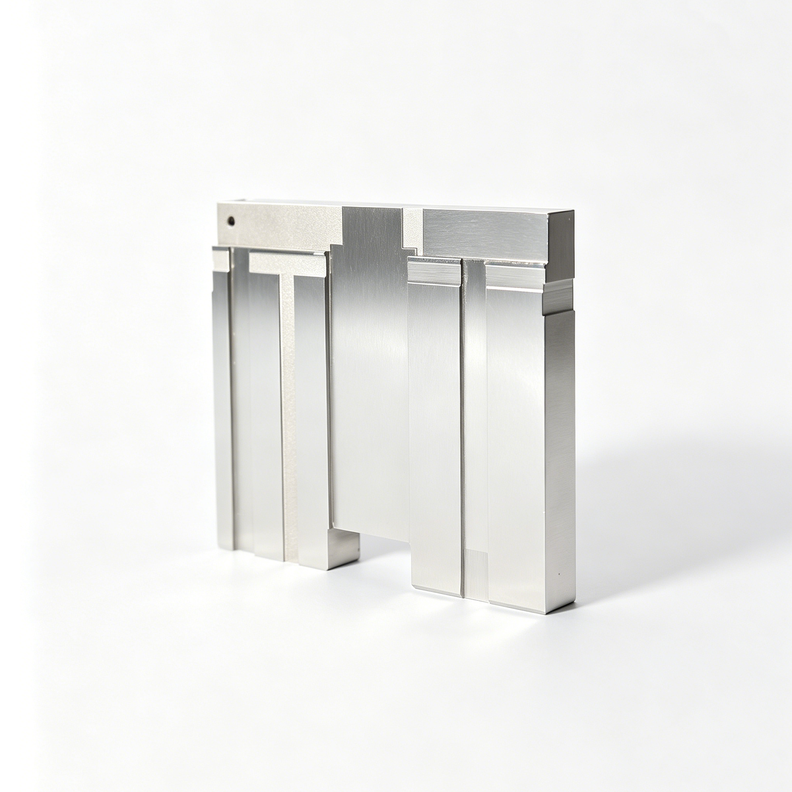

Related Component Families for Drawing Review






Mold Core Inserts: Engineering Advantages
A disciplined workflow for critical dimensions, process selection, inspection planning, and controlled revisions.
DFM Before Quotation
Review part geometry, material requirements, critical dimensions, and machining access before committing to a process route or production schedule.
Datum-Aware Planning
Align CNC, EDM, grinding, and inspection operations to the drawing datums so critical relationships remain visible throughout manufacturing.
Coordinated Process Routes
Plan milling, turning, wire EDM, sinker EDM, grinding, and fitting around feature geometry, access constraints, and finishing requirements.
Inspection Planned Early
Define measurement methods, report requirements, and critical-to-quality features early, so verification matches the agreed drawing and inspection plan.
Revision Visibility
Keep drawing updates, manufacturing changes, and delivery information visible, helping teams control revision status across mold core insert projects.
Traceable Communication
Exchange material, heat-treatment, quality, and delivery requirements in a documented workflow that supports informed sourcing and project coordination.
Precision Tooling and Machining Categories
Drawing-driven process routes for configurable components, from DFM review through machining, EDM, grinding, inspection, and documented delivery.

CNC Machining Services
Precision CNC machining services for drawing-based custom parts requiring coordinated milling, turning, EDM, grinding, and inspection. Review critical dimensions, datum relationships, material, quantity, and surface requirements before selecting a feasible manufacturing route.
Upload a Drawing
CNC Milling
Custom CNC milling services for prismatic parts, plates, inserts, pockets, and complex features. Tool access, clamping strategy, datum setup, corner geometry, and finishing allowances are reviewed against the drawing before production planning.
Upload a Drawing
CNC Turning
Precision CNC turning services for shafts, pins, sleeves, bushings, and rotational features. The process route considers concentricity, runout, diameters, threads, material condition, and any secondary milling, EDM, or grinding requirements.
Upload a Drawing
5-Axis Machining
5-axis CNC machining for features requiring multi-angle access, reduced setups, or controlled relationships across complex surfaces. Feasibility depends on part geometry, tool reach, fixture strategy, material condition, and the specified inspection approach.
Upload a Drawing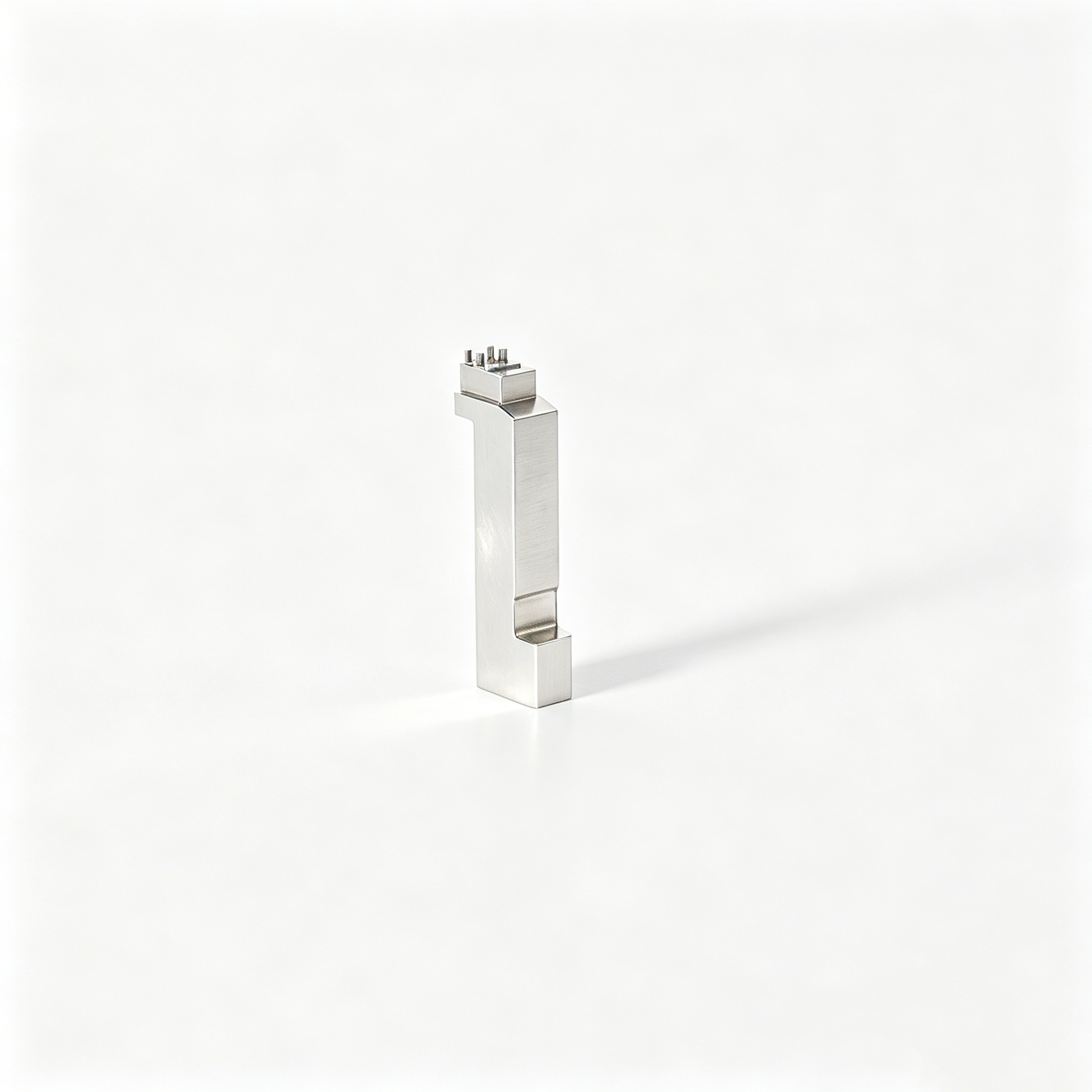
Swiss & Micro Machining
Swiss machining and micro machining for small-diameter, elongated, and detail-intensive components. Drawing review focuses on support requirements, feature sequence, tolerances, burr control, material behavior, and inspection methods suited to miniature geometry.
Upload a Drawing
Wire & Sinker EDM
Wire EDM and sinker EDM services for hardened material, sharp internal geometry, fine features, deep cavities, and profiles beyond conventional tool access. Electrode strategy, wire path, flushing, recast considerations, and finishing requirements are planned from the drawing.
Upload a Drawing
Precision Grinding
Precision surface and profile grinding for controlled flatness, parallelism, profile accuracy, and final-size correction. Grinding stock, heat-treatment condition, datum sequence, wheel access, and measurement criteria should be confirmed before processing.
Upload a Drawing
Mold Core & Cavity Inserts
Precision mold core and cavity inserts manufactured from customer drawings and configurable requirements. Process planning addresses steel grade, heat treatment, cooling or vent features, EDM access, mating surfaces, critical dimensions, and inspection evidence.
Upload a Drawing
Ejector & Ejection Components
Ejector pins, sleeves, and ejection components for mold mechanisms requiring controlled fit, stroke-related geometry, and wear considerations. Provide mating-part details, material and hardness requirements, surface needs, and critical clearance dimensions for review.
Upload a Drawing
Core Pins, Guide & Locating Components
Core pins, guide pins, and locating components produced to drawing-defined geometry and mating relationships. Dimensional priorities commonly include diameter control, straightness, concentricity, engagement length, fit class, surface condition, and heat-treatment sequence.
Upload a Drawing
Slides, Lifters, Gates & Mold Accessories
Mold slides, lifters, gates, and accessories for configurable tooling assemblies. Manufacturing review considers motion interfaces, shutoff geometry, wear surfaces, cooling or venting features, machining access, EDM needs, fitting allowance, and mating-component data.
Upload a Drawing
Connector Mold Components
Precision connector mold components for tooling that forms contact cavities, fine-pitch features, alignment details, and repeatable interfaces. Share component drawings, material requirements, critical pitch or positional dimensions, mating context, and inspection expectations.
Upload a Drawing
Stamping Die Components
Precision stamping die components for drawing-based die assemblies, including punches, inserts, guides, and wear parts. Process planning evaluates material and hardness, cutting-edge geometry, clearance relationships, grinding requirements, EDM strategy, and measurement needs.
Upload a Drawing
Injection, MIM, CIM & Overmolding Tooling
Tooling and component work associated with injection molding, metal injection molding, ceramic injection molding, and overmolding within verified production scope. Review feed, cavity, insert, material, thermal, and mating requirements before committing to a process route.
Upload a Drawing
Machining Materials
CNC machining materials selected from drawing and application requirements, including machinability, strength, corrosion resistance, stability, and heat-treatment response. Material grade, condition, traceability needs, and substitution restrictions should be defined in the RFQ.
Upload a Drawing
Surface Finishes & Heat Treatment
Surface finishing and heat treatment coordinated around functional requirements such as wear, corrosion resistance, friction, appearance, or dimensional stability. Specify the required process, condition, coverage, masking needs, hardness targets, and post-treatment inspection criteria.
Upload a Drawing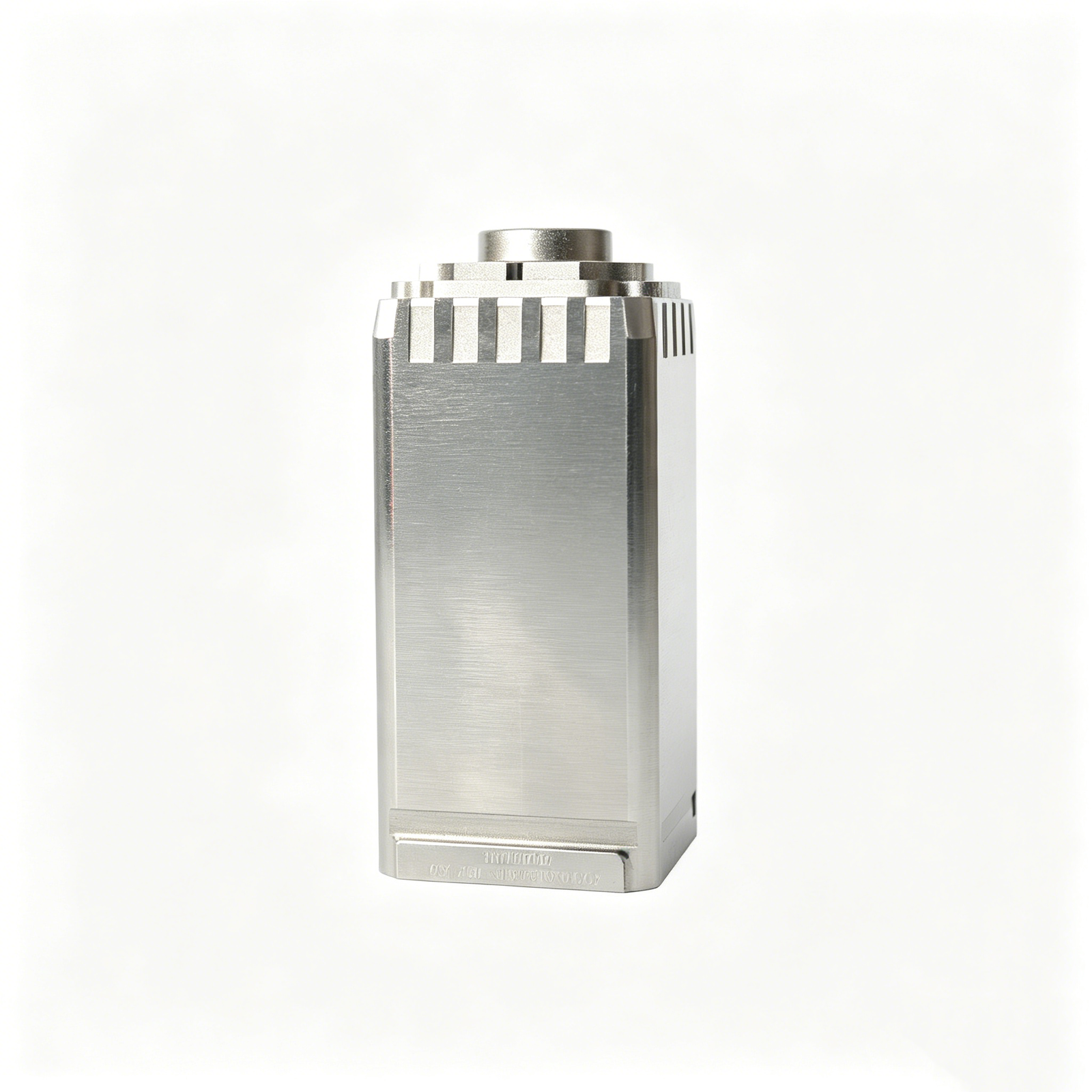
Quality, Metrology & Documentation
Precision inspection, metrology, and quality documentation matched to the order’s critical dimensions and agreed inspection plan. Define CTQ features, datums, measurement method, sampling or reporting expectations, material records, revision status, and traceability requirements upfront.
Upload a Drawing
Prototyping & Low-Volume Production
Rapid prototyping and low-volume manufacturing for drawing-driven parts requiring controlled revisions before broader release. Include quantity, material, critical dimensions, finishing needs, target date, and application context so DFM and process feasibility can be assessed.
Upload a DrawingMaterials for Mold Core Inserts and Tooling Components

Pre-Hardened Tool Steel
A practical choice for general mold core inserts and cavity components where stable machining and moderate service demands are required. Confirm supplied hardness, machining allowance, finish requirement, and any subsequent treatment during RFQ review.

Hot-Work Tool Steel
Used for inserts exposed to repeated thermal cycling, localized wear, or demanding shut-off conditions. CNC, EDM, grinding, heat-treatment sequence, and final hardness must be aligned to the drawing and molding application.


Cold-Work Tool Steel
Suitable for tooling features needing strong wear resistance, including certain cutting, forming, and precision die applications. Its machinability and grinding strategy depend on condition and hardness, so material documentation is reviewed with the RFQ.

Copper Alloy Inserts
Applied selectively where thermal conductivity supports local cooling or heat transfer in a tooling design. Alloy selection, interface geometry, wear exposure, and any EDM or finishing requirements require application-specific confirmation.
Mold Core Inserts: Precision Manufacturing Processes

CNC Milling
CNC milling establishes profiles, pockets, faces and datum surfaces on mold core inserts, with machining allowance planned for downstream EDM or grinding where geometry and tolerance requirements call for it.

CNC Turning
CNC turning supports rotational features such as diameters, shoulders, threads and concentric details. Process planning considers workholding, datum transfer and subsequent finishing requirements before production is committed.

Wire EDM
Wire EDM cuts conductive materials along controlled wire paths for narrow slots, precise contours and difficult-to-reach profiles. The route is evaluated against corner conditions, start-hole access, thickness and required finish.

Sinker EDM
Sinker EDM forms deep ribs, sharp internal features and enclosed geometry beyond practical cutter access. Electrode strategy, spark allowance, surface requirement and later fitting needs are reviewed from the drawing.

Precision Grinding
Precision grinding refines critical faces, diameters and datum relationships after suitable upstream machining or heat-treatment stages. Grinding stock, distortion risk and inspection references are aligned with the component requirements.

Fitting and Inspection
Fitting and inspection confirm functional relationships, critical dimensions and specified surface conditions against the agreed drawing revision. Measurement methods and reporting expectations are defined with the RFQ and inspection plan.
Mold Core Inserts: Supporting Tooling Features

Guide Components
Guide pins, bushes, and locating features can be specified around mold core inserts to support repeatable alignment between mold halves and protect critical mating geometry during assembly and service.

Locating Features
Dowel locations, keyways, shoulders, and anti-rotation details help establish datum relationships for interchangeable inserts, making fitting, inspection, and future replacement decisions clearer before machining begins.

Gate Inserts
Gate-area inserts can isolate complex or frequently revised geometry from the main block. Their design should account for resin flow, tool access, shutoff conditions, finishing, and replacement strategy.

Slides And Lifters
Slides and lifters may incorporate replaceable wear or forming elements where side actions, undercuts, or service access influence the tooling layout. SUUXIANG reviews interfaces, travel, and machining access from supplied data.

Ejector Components
Ejector pins, sleeves, blades, and related retention features are considered with part-release requirements, clearance interfaces, and inspection priorities. Drawing review helps identify where fitting or grinding allowances may be required.

Mold Accessories
Wear plates, stop blocks, support elements, and custom fixture-related accessories can be produced as drawing-defined components. Material, heat treatment, surface condition, and dimensional requirements should accompany the RFQ.
About SUUXIANG Precision Manufacturing
Established in 2010 in Chang’an Town, Dongguan, Guangdong, China, SUUXIANG is the public-facing brand of Dongguan SuuXiang Precision Mold Co., Ltd., founded and legally represented by XiaoCheng Huang. We help international engineering and sourcing teams translate drawings, models, and quality requirements into inspected mold core inserts, precision components, connector tooling, and custom machined parts.
Our practical production scope combines CNC milling and turning, multi-axis machining, wire EDM, sinker EDM, precision grinding, fitting, and inspection. Each route is selected around the part’s geometry, material condition, critical dimensions, surface requirements, and datum strategy rather than treated as a standard catalog process.
What distinguishes SUUXIANG is disciplined drawing review before production commitments. We work through DFM, machining access, EDM or grinding needs, heat-treatment sequence, inspection method, revision control, and delivery expectations so teams can evaluate manufacturability and exchange the evidence needed for a controlled RFQ.

Mold Core Inserts: Manufacturing Capabilities Explained
Drawing and DFM Review
Each mold core insert project begins with the drawing, 3D model where available, material, quantity, and application context. SUUXIANG reviews critical dimensions, datums, tolerance stack, tool access, surface requirements, and heat-treatment sequence before quotation or production commitments.
- Identify critical-to-quality dimensions and inspection priorities
- Review datum references and mating-component relationships
- Flag deep features, shutoffs, and access constraints early
- Confirm revision status before process planning

CNC and EDM Strategy
Process routing is selected around geometry and functional risk, not a generic machine list. CNC machining establishes accessible forms efficiently, while wire EDM or sinker EDM may be considered for narrow slots, sharp internal geometry, inaccessible features, or precision profiles in conductive materials.
- Match machining access to feature geometry
- Plan wire paths, start holes, and cutoff conditions
- Assess electrode needs for deep or complex details
- Sequence machining around required heat treatment

Grinding and Fitting Control
Grinding stock and fitting requirements should be defined before final finishing begins. For mold core inserts with sealing, sliding, or locating functions, SUUXIANG coordinates machining allowance, datum protection, surface requirements, and assembly interfaces so the finishing route supports the intended fit.
- Reserve appropriate stock for precision grinding
- Protect functional datums through later operations
- Review shutoff, slide, and locating interfaces
- Align finishing requirements with assembly needs

Inspection and Revision Visibility
Inspection planning follows the drawing and agreed quality expectations. SUUXIANG aligns measurement methods and documentation with critical features, then maintains visible revision and delivery information throughout the order. Final records must correspond to the verified inspection plan and released part revision.
- Define measurement methods for critical features
- Align reports with agreed inspection requirements
- Maintain traceability to the released drawing revision
- Provide RFQ details for material and delivery review

Why Engineering Teams Choose Drawing-Led Mold Core Inserts Manufacturing
Compare a review-first workflow for mold core inserts with generic quoting practices before production commitments.
← Swipe left or right to view →
Mold Core Inserts: From Drawing Review to Delivery
A controlled path that aligns DFM, process planning, critical dimensions and inspection requirements before shipment coordination.
Review Drawings and Requirements
We review 2D drawings, 3D models, material, quantity, application context, critical dimensions, datum strategy, surface requirements, delivery target and requested inspection documentation.
Confirm DFM and Process
The manufacturing route is assessed for machining access, tolerance stack, heat-treatment sequence, machining allowance, electrode strategy, wire paths, grinding stock and fitting considerations.
Machine Core Insert Features
Approved mold core inserts proceed through the appropriate CNC milling, turning, multi-axis, micro-machining or preliminary operations, with revision information kept visible throughout production.
Apply EDM and Grinding
Wire EDM, sinker EDM and precision grinding address features requiring controlled access, geometry or finish, according to the agreed drawing and process plan.
Fit Inspect and Document
Components are fitted where required, then inspected against the order-specific plan. Measurement results, traceability requirements and final documentation are checked before release.
Pack and Coordinate Shipment
Accepted parts are packed for the component geometry and shipment route, while delivery coordination reflects the confirmed order, documentation requirements and destination details.
How to Work With SUUXIANG
A drawing-led path from manufacturability review through documented production coordination for mold core inserts.
Submit Your Drawing Package
Provide 2D drawings, available 3D models, material, quantity, delivery target, and critical dimensional, surface, heat-treatment, inspection, or mating-component requirements.
Review Manufacturability Together
SUUXIANG reviews datum strategy, tolerances, machining access, EDM requirements, grinding allowance, and inspection priorities before aligning the proposed process route and quotation.
Confirm Production Details
Confirm revision status, approved specifications, sampling or production quantity, quality documentation, and delivery requirements before machining begins for your mold core inserts.
Track Coordinated Delivery
Receive visible coordination on production progress, inspection planning, revision control, and shipment readiness, with final documentation matched to the verified order requirements.
Mold Core Inserts: Certifications and Quality Documentation
Mold Core Inserts: Customer Project Feedback and Outcomes
Verified customer testimonial pending approval. This placement is reserved for a documented mold core insert project outcome, including agreed delivery, inspection, or revision-control evidence before publication.
Verified customer testimonial pending approval. Publish only after the customer approves the attribution and a specific, traceable project result, such as inspected dimensions, delivered quantity, or revision response.
Verified customer testimonial pending approval. A final quote should describe the customer’s actual drawing-review, machining, EDM, grinding, or inspection outcome without implying unverified capability or performance figures.
Complete Buyer’s Guide to Mold Core Inserts
Practical guidance on the information, evidence, and commercial details needed to assess a drawing-led mold component inquiry.
What information do you need to quote mold core inserts?
Is there a minimum order quantity for mold core inserts?
How long does it take to manufacture custom mold core inserts?
Can SUUXIANG make a prototype or sample before a larger order?
How are mold core insert materials and heat treatment confirmed?
Can I request inspection reports for mold core inserts?
How does SUUXIANG protect drawings and intellectual property?
What payment and shipping details should I provide with an RFQ?
Complete Buyer’s Guide to mold core inserts
Use this decision framework to specify mold core inserts, compare materials and manufacturing methods, evaluate drawing-review and quality criteria, select capable suppliers, and avoid costly design, sourcing, and production mistakes.
1. What Are mold core inserts?
1. Mold core inserts are precision, separately machined sections installed in the core side of an injection mold; they form part-side internal geometry such as bores, deep ribs, under-feature details, or local shutoffs. The surrounding cavity creates the exterior shape, while resin flows around the core. https://www.aberdeentech.com/blog/mold-manufacturing-process
2. A core insert is not a cavity insert, which defines external surfaces, nor a core pin, which is typically a narrower feature-forming element. It is also not a loose core removed with the molded part each cycle, or a product-side metal insert placed in the mold for overmolding.
3. Replaceability is justified when a local feature is difficult to machine, polish, vent, cool, revise, or renew after wear. Choose an insert strategy over one solid core when its joint line and datum location can be controlled without creating unacceptable flash, leakage, weakened steel, or blocked cooling; confirm this in drawing review before releasing manufacture. https://firstmold.com/guides/mold-inserts
2. Evolution of Mold Insert Tooling
Before CNC and EDM became routine moldmaking processes, complex features were commonly cut into larger core blocks, so a localized design change could consume substantial steel and rework time. Modular mold core inserts separated high-wear, deep-feature, or difficult-to-machine areas from the supporting mold block, making targeted replacement practical.
CNC milling established repeatable geometry from digital models, while wire EDM and sinker EDM made narrow slots, sharp internal details, and restricted-access features more manufacturable. Heat treatment then requires sequence planning: machining allowance, distortion risk, finish grinding, and the dimensions to inspect after each critical operation must be defined on the drawing.
Today, revision-controlled 2D drawings and 3D models are procurement requirements, not administrative extras. A buyer should require insert identification, datum references, material and heat-treatment specifications, inspection methods, and revision status so replacement mold core inserts can fit predictably without turning a low-risk modification into an assembly problem.
3. Types of mold core inserts
Insert geometry should follow the molded feature, service risk, and machining access—not a catalog label. Specify the retention datum and replacement path on the drawing before release.
| Insert Family | Typical Feature | Primary Limitation |
|---|---|---|
| Core pin | Boss or connector hole | Deflection |
| Profile block | Rib or wear zone | Split-line flash |
| Loose insert | Undercut | Manual handling |
| Venting/conductive | Gas trap or hot spot | Maintenance |
Core Pins

Core pins form bosses, small holes, and connector features. A headed, shouldered, or pinned seat resists movement; long slender pins need deflection and cooling review.
Blocks And Profile Inserts

Rectangular blocks suit deep ribs, shutoffs, and wear zones. Screw-and-dowel retention supports replacement, while CNC access, EDM corners, and polishing direction govern the split line.
Round And Threaded Inserts

Round inserts simplify bore-based location and rotation control needs deliberate flats, keys, or pins. Threaded and shaped inserts suit local forms but require sufficient engagement and tool access.
Loose Inserts

Loose inserts release undercuts or enclosed geometry after each cycle. They add handling, orientation, and cycle-time risk, so use them only when slides or lifters are unsuitable.
Venting And Conductive Inserts

Venting inserts address trapped-gas areas; high-conductivity inserts target hot local geometry. Both require sealing, maintenance access, and cooling review because interfaces can flash or weaken surrounding steel.
4. Materials for mold core inserts
Material selection begins with the resin, insert geometry, finish target, cycle-time objective, and projected shot volume. Specify the material and heat-treatment condition on the drawing rather than accepting a generic steel substitution.
| Material | Hardness Potential | Key Strength | Typical Fit |
|---|---|---|---|
| P20/718H | Pre-hardened | Machinable, polishable | Moderate-volume general resin |
| H13/1.2344 | High after treatment | Hot strength, wear | Higher-temperature molding |
| S136 | High after treatment | Corrosion resistance, polish | Corrosive resin or high finish |
| BeCu alloy | Lower than tool steel | High thermal conductivity | Localized cooling inserts |
Compare Candidate Materials
P20/718H are pre-hardened choices for moderate service; H13/1.2344 suits hotter duty; S136 supports corrosion-sensitive molding; beryllium-copper alloys move heat quickly in local hot spots.
Material Trade-Offs
Glass-filled resin raises wear demand, while PVC, flame-retardant, or humid processing can justify corrosion resistance. High polish requirements favor clean, polishable grades; conductive alloys need placement review because strength and wear behavior differ from tool steel.
Request Production Evidence
Each RFQ should request mill certificate, material grade, heat number, hardness range, heat-treatment record, and final inspection plan. Cooling capacity affects cycle time and part quality; review core cooling with the molding condition. Source: https://www.eastman.com/content/dam/eastman/corporate/en/literature/s/sptrs5344.pdf
5. Custom mold core inserts Options
Two drawing-controlled groups keep custom options clear: functional features affect molding, fit, cooling, or service life; identification features support handling and revision control. SUUXIANG should review both groups against the released drawing before machining begins.
| Option Group | Specify | Confirm Before Machining |
|---|---|---|
| Geometry | Datums, CTQ limits, access | Inspection reference |
| Surface | Polish, EDM, texture boundary | Coating effect |
| Identification | Part ID, revision, location | Marking method |
Functional Geometry
Three geometry inputs are profile, tool access, and interchange envelope. Define ribs, shutoffs, radii, anti-rotation features, and assembly interfaces on the model.
One datum scheme should govern machining and inspection. Flag CTQ dimensions, limits, and measurement references.
Surface And Thermal Features
Two surface categories require separate specifications: functional texture-ready faces and cosmetic areas. State polish grade, texture boundary, and EDM surface condition.
One vent or cooling interface needs location, size, depth, and sealing intent. Confirm coating masks and post-coating dimensional effects.
Production Release Data
Before release, SUUXIANG reviews 2D drawing, 3D model, material, heat treatment, quantity, and revision. Provide mating-part context where fit depends on assembly.
Each marked feature needs an inspection method and acceptance record. Interchangeable revisions require ID marking and controlled revision status.
6. Mold Core Insert Quality Elements
Quality begins at the insert-to-pocket interface, not at final polish. Mold core inserts should be reviewed as functional interfaces with defined datums, sealing, thermal access, and replacement requirements.
Fit, Seal, And Ejection
0.01 mm of uncontrolled clearance can become a flash path under molding pressure. Specify sealing-face geometry, fit limits, draft direction, corner radii, and a burr-free edge condition; inadequate draft or sharp transitions can cause sticking, galling, and difficult assembly.
Retention And Thermal Control
2 independent locating features are preferable where rotation would alter a critical feature. Define retention by screws, keys, pins, or a lock geometry, plus cooling and venting access; weak retention causes positional shift, while blocked cooling can create heat imbalance and accelerated wear.
Inspection Evidence And Acceptance
100% inspection is appropriate for identified critical dimensions, sealing interfaces, and datum relationships. Request the drawing revision, material and heat-treatment evidence when specified, dimensional report, inspection method, datum setup, surface or burr acceptance criteria, and documented disposition of deviations.
7. Choosing a mold core inserts Supplier
Three functions—engineering, quality, and procurement—should score the same supplier file before an RFQ becomes a release. For mold core inserts, demonstrated controls matter more than capability statements.
| Check | Demonstrable Evidence | Owner |
|---|---|---|
| Drawing review | Marked-up DFM and revision log | Engineering |
| Quality plan | Traceability and inspection format | Quality |
| Delivery plan | Milestones and packaging method | Procurement |
Drawing Review Evidence
One reviewed drawing should return with CTQs, datums, tolerance concerns, tool-access limits, and a proposed CNC, EDM, or grinding route.
One marked-up file, DFM response, and revision identifier are stronger evidence than a generic assurance.
- CTQ and datum review
- EDM or grinding rationale
- Open-question log
Process And Material Control
Two linked records should show material traceability to the order and the specified heat-treatment route.
One process plan should connect actual geometry to CNC, wire or sinker EDM, grinding, fitting, and inspection methods.
Release And Delivery Discipline
One checklist should assign technical approval to engineering, evidence review to quality, and commercial acceptance to procurement.
One release package should define inspection-report format, revision acknowledgement, protective packaging, milestones, and escalation for lead-time risk.
8. Common mold core inserts Buying Mistakes
Before release, mold core inserts need a joint drawing review by design, molding, quality, and sourcing. Most rework begins when a requirement is assumed rather than recorded against a datum, revision, or inspection method.
Incomplete Drawing Definition
One incomplete package can omit datums, GD&T, material condition, or heat-treatment state; machining then proceeds on assumptions and inspection cannot prove intent. Ask: Which revision-controlled dimensions, datums, material state, and report requirements govern release?
Functional Risks Left Unreviewed
Two molding factors—resin shrinkage and venting—can change fit, flash risk, filling, and part release even when insert dimensions match the drawing. Ask: Has the molding team approved shrinkage, vent locations, shutoffs, and mating-component context before manufacture?
Cost Decisions Without Lifecycle Context
Three avoidable choices are blanket tight tolerances, ambiguous surface-finish notes, and no spare-insert plan; each can add grinding, EDM, fitting, or downtime cost. Ask: Which features are truly critical, what finish is functional, and which wear-prone inserts require approved spares? Unit price alone cannot answer that question.
9. From Drawing to Production Release
A controlled release for mold core inserts begins before machining, when the buyer supplies the current 3D model, dimensioned 2D drawing, application, resin, quantity, and required inspection evidence. Each approval gate should identify one accountable owner and a dated revision.
Input Package And DFM
Gate 1 compares model and drawing revisions, datums, critical dimensions, surface callouts, material, hardness, and mold-side orientation.
Gate 2 returns DFM feedback on tool access, EDM electrodes or wire paths, grinding stock, shutoffs, venting, cooling interfaces, and likely fit risks.
Specification Freeze
Gate 3 locks the released drawing, 3D file, tolerance interpretation, heat-treatment sequence, inspection plan, quantity, and delivery target.
One buyer-side engineering owner should approve functional requirements; SUUXIANG should record the agreed revision and any deviations before production starts.
First Article And Replenishment
Gate 4 reviews the first article or agreed sample against the inspection plan, then validates seating, alignment, shutoff, and molded-part fit in the actual mold.
Gate 5 closes revisions with a dated change record and defines spare inserts, identification, retained files, and reorder triggers for replenishment.
10. mold core inserts Pricing and Cost
Two quotations can describe the same geometry yet cover different process routes, acceptance criteria, and replacement exposure. Compare the priced drawing revision, included inspection record, packaging, and change-control response before selecting the lowest unit figure.
One repeat order should usually reduce programming and fixture recovery, but hardened material, EDM detail, tight datums, polishing, and expedited scheduling can still dominate cost. Ask each supplier to identify excluded operations and the cost effect of a revised critical dimension.
| Order profile | Primary cost drivers | Quotation comparison point |
|---|---|---|
| 1 prototype | Material, heat treatment, CNC setup, EDM electrodes or wire path | Separate setup from unit cost; confirm inspection method |
| 5–20 pieces | Repeat machining, grinding stock, tolerance and finish | Check whether first-article evidence is included |
| Repeat release | Revision status, fixture reuse, replacement risk | Compare documented revision control and replacement lead time |
| Expedited order | Queue priority, extra setups, inspection timing | Price schedule risk and delivery confirmation separately |
Upload Your Drawing for Mold Core Inserts
Include material, quantity, critical dimensions, quality requirements, and target delivery date for a focused drawing review and quotation discussion.