
Mold Interlocks Built From Your Drawing
Move from drawing review to inspected mold interlocks with DFM, CNC machining, EDM, grinding, and controlled dimensional verification.
Representative Precision Tooling Components





Representative Components and Drawing-Based Quotation




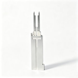




Mold Interlocks for Critical Alignment Control
Drawing-led planning for manufacturability, alignment surfaces, and inspection evidence before production begins.
DFM Before Quotation
Review engagement geometry, tool access, critical dimensions, material requirements, and heat-treatment sequence before committing to a production route.
Datum-Focused Planning
Define functional datums and measurement references so mating faces, locating features, and alignment relationships can be evaluated consistently.
EDM and Grinding Strategy
Select CNC, wire EDM, sinker EDM, and grinding operations around geometry, finishing needs, machining allowance, and access constraints.
Inspection Plan Alignment
Identify critical features, inspection methods, reporting needs, and acceptance criteria from the drawing and confirmed project requirements.
Visible Revision Control
Keep drawing revisions, clarifications, and process-impacting changes visible throughout review, manufacturing, inspection, and delivery coordination.
Traceable Project Communication
Maintain clear exchanges on materials, quantities, quality expectations, delivery targets, and mating-component context for drawing-based mold interlocks.
Mold Interlocks and Precision Component Families
Drawing-driven component families for alignment, motion, forming, and inspection-critical tooling requirements.

CNC Machining Services
Precision CNC machining services translate approved drawings into custom tooling and production parts through planned milling, turning, EDM, grinding, and inspection. Feasibility depends on material, geometry, critical dimensions, surface requirements, quantity, and the agreed inspection plan.
Upload a Drawing
CNC Milling
Custom CNC milling services support prismatic mold and tooling components with pockets, ribs, faces, holes, and datum features. Tool access, clamping strategy, corner radii, stock allowance, and critical-dimension relationships should be reviewed before the process route is committed.
Upload a Drawing
CNC Turning
Precision CNC turning services produce rotational features such as pins, sleeves, bushings, shafts, and locating elements. Drawings should define functional diameters, runout, concentricity, shoulders, threads, material condition, and any downstream grinding or heat-treatment sequence.
Upload a Drawing
5-Axis Machining
5-axis CNC machining helps reach angled faces, compound contours, and multi-sided features while reducing unnecessary re-clamping. The process review considers cutter reach, collision clearance, datum transfer, surface requirements, and whether complex geometry requires EDM or finishing operations.
Upload a Drawing
Swiss & Micro Machining
Swiss machining and micro machining support small, slender, and detail-intensive components where stability and feature control are central concerns. Buyers should identify critical diameters, length-to-diameter relationships, burr limits, material condition, mating context, and inspection requirements.
Upload a Drawing
Wire & Sinker EDM
Wire EDM and sinker EDM services address hardened materials, sharp internal geometry, narrow slots, delicate profiles, and features inaccessible to conventional cutters. Electrode design, wire path, flushing, recast-layer considerations, finish requirements, and subsequent fitting must be planned from the drawing.
Upload a Drawing
Precision Grinding
Precision surface and profile grinding provides controlled flatness, parallelism, thickness, profiles, and finished datum relationships on tooling components. The route should account for heat-treatment distortion, retained grinding stock, wheel access, surface specification, and the inspection method for critical features.
Upload a Drawing
Mold Core Inserts & Mold Cavity Inserts
Precision mold core and cavity inserts are configurable forming components built around the part geometry, steel specification, cooling and venting needs, molding material, and maintenance approach. Drawing review should establish parting surfaces, shutoffs, datum strategy, EDM areas, heat treatment, and inspection-critical dimensions.
Upload a Drawing
Ejector & Ejection Components
Ejector pins, sleeves, and ejection components are selected and manufactured around stroke, guidance, load, clearance, and molded-part release requirements. Functional fits, hardness condition, surface needs, head geometry, lubrication context, and mating plates should be defined before production.
Upload a Drawing
Core Pins, Guide & Locating Components
Core pins, guide pins, and locating components establish repeatable forming, alignment, and assembly relationships in a mold. Their design review considers working diameter, support length, mating fit, wear exposure, material and heat treatment, replacement needs, and datum references used for inspection.
Upload a Drawing
Slides, Lifters, Gates & Mold Accessories
Mold slides, lifters, gates, and accessories manage side actions, release geometry, material flow, and assembly interfaces. Production planning depends on travel, angles, load paths, wear surfaces, shutoff geometry, cooling constraints, fitting requirements, and the relationship to adjacent mold components.
Upload a Drawing
Connector Mold Components
Precision connector mold components support fine-pitch cavities, terminal-related geometry, multi-cavity consistency, and repeatable assembly in connector tooling. Drawings should clarify critical feature locations, polish or EDM expectations, wear areas, material condition, datum strategy, and inspection evidence.
Upload a Drawing
Stamping Die Components
Precision stamping die components include punches, dies, guide elements, plates, and forming details produced to the approved die design. Process planning considers strip-material interaction, cutting or forming loads, clearance, wear, heat treatment, grinding stock, assembly fits, and maintenance requirements.
Upload a Drawing
Injection, MIM, CIM & Overmolding Tooling
Injection, MIM, CIM, and overmolding tooling components are evaluated according to the material system, molding behavior, part geometry, and tool construction requirements. Review topics include gates, vents, shutoffs, core details, insert interfaces, heat treatment, surface condition, and dimensional verification.
Upload a Drawing
Injection Mold Components for MIM, CIM & Overmolding Tooling
CNC machining materials are reviewed against strength, hardness, corrosion resistance, wear, machinability, heat-treatment condition, and application environment. The RFQ should state the specified grade or approved equivalent, material certification needs, stock form, and any material-specific surface or inspection requirements.
Upload a Drawing
Surface Finishes & Heat Treatment
Surface finishing and heat treatment are planned as part of dimensional control, not as afterthoughts. Requirements should identify the intended process, hardness or finish target where applicable, masking or critical surfaces, post-treatment grinding needs, corrosion considerations, and documentation expectations.
Upload a Drawing
Quality, Metrology & Documentation
Precision inspection, metrology, and quality documentation are aligned with the drawing’s critical dimensions, datums, tolerances, and agreed reporting needs. Before production, define measurement methods, sampling or full-inspection expectations, material records, revision status, and the documents required with delivery.
Upload a Drawing
Prototyping & Low-Volume Production
Rapid prototyping and low-volume manufacturing support drawing validation, tool trials, bridge requirements, and controlled repeat orders. A practical RFQ identifies quantity, revision level, material and treatment requirements, critical dimensions, surface priorities, inspection needs, and the target delivery context.
Upload a DrawingMold Interlocks: Materials for Tooling Duty

Pre-Hardened Tool Steel
A practical choice for many mold interlocks where stable machining and moderate service duty are required. It supports efficient CNC and EDM work, while hardness, mating contact, and final inspection criteria should be confirmed per drawing.

Through-Hardening Tool Steel
Used for interlock faces requiring higher wear resistance after controlled heat treatment. The process plan must account for machining allowance, distortion risk, grinding stock, and verification of critical alignment dimensions after hardening.

Cold-Work Tool Steel
Suitable for demanding contact areas where wear resistance and compressive strength matter. It is commonly considered for durable alignment components, with electrode strategy, heat-treatment route, and finish-grinding requirements reviewed before production.

Hot-Work Tool Steel
Considered when tooling duty involves repeated thermal cycling alongside mechanical loading. Its toughness and heat-checking resistance can be relevant, but material grade, hardness target, and surface condition remain application-dependent decisions.

Stainless Tool Steel
Selected when corrosion resistance is important for the molding environment or material handled. It can support precision interlock applications, provided machinability, heat treatment, mating wear, and required inspection documentation are defined in the RFQ.
Mold Interlocks: Machining, EDM, Grinding and Fitting


Wire EDM
Wire EDM produces precise profiles, narrow slots and complex through-features where conventional tool access is limited. The wire path, start-hole strategy and finish requirements are coordinated with the drawing’s critical alignment surfaces.

Sinker EDM
Sinker EDM forms detailed internal geometry, sharp-feature requirements and difficult-to-reach areas using a planned electrode strategy. Electrode wear, spark finish and subsequent fitting needs are considered before the process route is confirmed.


Fitting and Inspection
Fitting verifies the functional relationship between mating mold interlock components, while inspection follows the agreed critical-dimension plan. Results, revision status and any required reporting are kept aligned with the confirmed order requirements.
Mold Interlocks Accessories and Complementary Hardware

Locating Features
Dowel locations, keyways, register shoulders and mating pockets can be machined with mold interlocks when the assembly needs controlled positional reference across plates, inserts or serviceable subcomponents.

Mounting Fasteners
Socket-head screws, threaded holes and counterbores are defined around the required clamp load, access direction and service sequence. Share fastener specifications and clearance requirements during drawing review.

Compression Springs
Spring pockets and retention features may be added for return, preload or travel-control functions near the interlock assembly. Spring force, installed height, stroke and operating environment should be confirmed by the tool designer.

Wear Plates
Replaceable wear plates or guided sliding surfaces can protect adjacent mold hardware where repeated movement creates contact load. Material, heat treatment, lubrication approach and grinding requirements remain application-dependent.

Identification Marking
Part numbers, revision marks, cavity identification or orientation marks can support assembly and traceability. Specify marking method, position and legibility expectations so they do not affect critical surfaces or functional fit.

Protective Packing
Rust-prevention treatment, individual separation and labeled protective packing can be planned for finished mold interlocks and related hardware. Define shipment duration, storage conditions and any customer packaging documentation requirements with the RFQ.
About SUUXIANG Mold Interlocks
Established in 2010 in Chang’an Town, Dongguan, Guangdong, China, Dongguan SuuXiang Precision Mold Co., Ltd. operates internationally under the SUUXIANG brand. XiaoCheng Huang is the founder and legal representative. We help engineering, sourcing, and quality teams turn drawings into inspected precision mold components, custom CNC parts, connector tooling, and mold interlocks.
Our workflow begins with the drawing, 3D model, material, quantity, application, and quality requirements. Before quotation or production commitments, we review critical dimensions, datum strategy, machining access, EDM requirements, grinding allowance, heat-treatment sequence, and inspection expectations.
SUUXIANG combines CNC machining, wire and sinker EDM, precision grinding, fitting, and inspection within a controlled project workflow. What distinguishes our approach is visible revision control, process planning matched to the part, and documentation aligned with the agreed inspection plan.

Mold Interlocks: Critical Capabilities in Depth
Datum and Critical-Dimension Review
Before quotation, SUUXIANG reviews drawing datums, mating relationships, shutoff surfaces, and critical alignment dimensions for mold interlocks. The review identifies tolerance-stack risks, functional references, and measurement requirements so the manufacturing route reflects how the component must locate in the assembled tool.
- Confirm functional datums and mating surfaces
- Identify critical-to-quality alignment dimensions
- Review tolerance stacks across paired components
- Define inspection references before production

CNC and EDM Route Planning
Mold interlocks often require more than a standard milling sequence. SUUXIANG plans machining access, electrode strategy, wire paths, corner conditions, and heat-treatment sequence against the approved drawing, helping engineering teams evaluate practical process choices before production commitments are made.
- Assess milling access and internal corner conditions
- Plan wire EDM and sinker EDM where required
- Review electrode geometry and burn locations
- Coordinate process sequence with material requirements

Grinding and Fitting Strategy
Precision alignment depends on controlled stock removal and the relationship between complementary faces. SUUXIANG evaluates grinding allowance, hardened-condition finishing, contact surfaces, and fitting needs so mold interlocks can be produced against the intended assembly relationship rather than treated as isolated machined parts.
- Reserve suitable grinding stock in the route
- Review hardened-state finishing requirements
- Identify complementary contact and locating faces
- Clarify fitting expectations for paired parts

Inspection and Revision Control
Inspection planning is linked to the drawing revision, agreed datums, and defined critical features. SUUXIANG keeps revision and delivery information visible through the project, with final documentation aligned to the order and the verified inspection plan for the specific mold interlocks supplied.
- Match inspection points to approved drawing revisions
- Use agreed datums for dimensional verification
- Clarify reporting and documentation requirements
- Maintain traceable project communication

Why Choose SUUXIANG for Mold Interlocks
Compare a documented engineering workflow with a generic quote-only sourcing path.
← Swipe left or right to view →
Mold Interlocks: From Drawing Review to Delivery
A drawing-driven route that keeps alignment requirements, process decisions, inspection expectations, revisions and shipment coordination visible before production begins.
Review Drawings and Requirements
We review 2D drawings, models, material, quantity, critical dimensions, datums, surface requirements, application context, inspection needs and target delivery date before quotation.
Confirm DFM and Process Route
The project discussion identifies machining access, tolerance stack risks, heat-treatment sequence, EDM electrode or wire-path needs, grinding stock and fitting considerations for the proposed mold interlocks.
Machine Critical Component Features
CNC milling, turning, multi-axis work and applicable micro-machining produce the planned geometry, while process control follows the approved drawing revision and dimensional priorities.
Apply EDM Grinding and Fitting
Wire EDM, sinker EDM, precision grinding and fitting are scheduled where required to establish functional faces, controlled clearances and mating relationships without bypassing the planned sequence.
Inspect Document Pack and Ship
Final inspection follows the verified plan; documentation is matched to the order, then packing and shipment coordination proceed with revision and delivery information kept visible.
Work With SUUXIANG on Mold Interlocks
Move from drawing review to controlled production with requirements, critical dimensions, inspection expectations, and revisions documented before manufacture proceeds.
Submit Your Drawing Package
Provide 2D drawings, 3D models when available, material and heat-treatment requirements, quantity, delivery target, application context, and critical dimensional or surface priorities.
Review DFM and Quotation
Align on datum strategy, tolerance stack, machining access, EDM or grinding needs, inspection method, revision status, and the proposed manufacturing route before commitments are made.
Approve First-Off Expectations
Where sampling or first-off approval applies, confirm the acceptance criteria, measurement reporting, mating-component considerations, and any required feedback loop before continued production.
Release Controlled Production
SUUXIANG coordinates the agreed CNC machining, EDM, grinding, fitting, and inspection sequence while keeping drawing revisions and project information visible throughout manufacturing.
Confirm Inspection and Delivery
Review order-matched inspection documentation and delivery details against the agreed plan, then coordinate shipment of mold interlocks and related precision components.
Certifications and Quality Evidence to Confirm Per Project
Customer-Reference Publication Policy
Customer references are published only after the customer approves the project scope, measurable outcome, and attribution.
Project evidence is published only when the relevant inspection record, revision-control context, and result are verified and approved for disclosure.
Reference material is released only after the quotation scope, drawing revision, quantity, delivery context, and reported outcome are verified.
Mold Interlocks FAQ for RFQ and Manufacturing Decisions
Practical answers for teams preparing drawing-based precision tooling component inquiries.
What information should I send for a mold interlocks quotation?
Is there a minimum order quantity for custom mold interlocks?
Do I need both a 2D drawing and a 3D model?
Can SUUXIANG review mold interlocks for DFM before quotation?
Which materials and heat treatments are suitable for mold interlocks?
Can you provide inspection reports with custom tooling components?
How should I plan lead time for a mold interlocks order?
How are revisions, shipping and payment handled for an international RFQ?
The Complete Buyer’s Guide to mold interlocks
Use this practical framework to specify mold interlocks, compare alignment-lock options, evaluate drawing-based suppliers, control manufacturing risk, and avoid the design, inspection, and purchasing mistakes that cause mismatch, flash, or premature wear.
1. What Are mold interlocks?
Two mating, precision-machined surfaces make up a mold interlock: they engage as the tool closes to positively register mold halves, plates, cavities, or cores under clamping and injection loads. Tapered or angled contact converts lateral forces into controlled bearing contact rather than allowing free side-to-side drift.
Guide pins and bushings serve a different job: they guide opening, closing, and assembly, but their running clearance permits motion. An interlock therefore supplements—not replaces—the guide system by locating critical faces at full closure; this distinction is described at https://www.improve-your-injection-molding.com/plastic-injection-mold-design.html.
0.01 mm of relative movement can matter at a fine parting line or shutoff, even when it is not visible during handling. Positive registry helps limit parting-line mismatch, flash risk, dimensional variation, and progressive shutoff-face wear by resisting lateral displacement cycle after cycle.
2. Evolution of Mold Alignment Methods
Leader pins and bushings were originally intended to guide mold halves during assembly and closing, but their sliding clearance cannot by itself provide rigid lateral registration under molding load. As cavities, inserts, and multi-plate stacks added interfaces, designers needed positive metal-to-metal mold interlocks at the surfaces governing parting-line position.
Side interlocks became a practical response where edge access is available, while tapered and angled-square forms address layouts obstructed by slides or other mold-base features. Industry guidance identifies these three locking approaches and shows why location must be evaluated against surrounding mechanisms: https://www.injectionmould.org/2019/04/03/injection-mold-interlocks
Two decisions now belong on the drawing: the registration datum and the load path after clamp force and cavity pressure act on the tool. Specify which plates, inserts, or cavity/core features must remain registered, where contact is permitted, and how side force is directed away from a sealing edge; generic mold-base guidance alone leaves those risks unresolved.
3. Types of mold interlocks
Six common mold interlocks differ mainly by closing direction and usable plate space. Selection starts with the datum to protect, then checks whether moving hardware occupies the preferred lock location.
| Type | Engagement And Space | Purpose And Typical Use | Strengths And Limitations |
|---|---|---|---|
| Side | Lateral; edge space | Half alignment; open perimeter | Simple; conflicts with slides |
| Tapered | Closing axis; internal pocket | Plate or half registry | Positive pull-in; needs depth |
| Angled-Square | Angled; internal pocket | Heavy lateral control | Robust; occupies plate volume |
| Top Lock | Vertical; stacked plates | Ejector or stripper alignment | Accessible; layout-dependent |
| Insert Or Cavity | Local; insert envelope | Core/cavity registry | Protects local datum; reduces insert space |
| Custom Geometry | Application-specific | Constrained plate layouts | Fits clashes; requires drawing review |
Perimeter Lock Choices
Four perimeter-side positions are common when edge clearance is available. Side locks resist lateral mismatch efficiently, but slides, lifting holes, or water layouts may require diagonal relocation.
Internal Alignment Choices
Two internal approaches suit plates whose edges are occupied. Top locks engage through the plate stack, while insert locks locate a cavity or core directly; both require serviceable installation access.
Layout-Driven Customization
One custom geometry can combine angled faces, offsets, or local insert features where standard hardware clashes. Its drawing should define datums, engagement travel, relief, fastening, and inspection points before machining.
4. Materials and Heat Treatment for mold interlocks
Two variables—steel grade and heat-treatment route—govern whether mold interlocks resist contact wear without becoming brittle. Match them to resin environment, cycles, lubrication access, and datum-controlled bearing faces.
| Service Case | Material Strategy | Required Evidence |
|---|---|---|
| Prototype tool | Machinable, correctable steel | Grade and supply condition |
| Production mold | Toughness plus specified hardness | Treatment certificate and readings |
| Corrosive environment | Corrosion-aware steel and preservation | Surface and storage controls |
Prototype Versus Production Steel
Prototype tools prioritize machinability and controlled correction over maximum hardness. Specify grade, supply condition, and expected cycle range rather than copying a production callout.
Production molds require a steel-and-treatment route matched to contact load and impact. Confirm the post-treatment hardness range, toughness requirement, and allowable distortion.
Surfaces, Corrosion, And Lubrication
Critical shutoff and sliding faces need defined finish requirements and, where justified, a coating requirement. Roughness, edge condition, and grinding direction can affect galling and bedding-in.
Corrosive resin, humid storage, and dry running raise wear risk. State lubricant type, relubrication access, preservation method, and surfaces that must remain coating-free.
Drawing Questions And Evidence
Three records should close the material loop: material certificate, heat-treatment certificate, and hardness readings at agreed locations. Identify each critical bearing face and its datum before manufacture.
Final inspection should verify dimensions after heat treatment and finish grinding. Ask the supplier how distortion is controlled, which treatment method applies, and what revision is inspected.
5. Mold Interlock Drawing and Customization Requirements
A manufacturable interlock RFQ starts with the assembly function, not a nominal size. SUUXIANG reviews the drawing package for datum logic, mating conditions, process access, and inspection expectations before confirming a route.
| Requirement | 2D Drawing | 3D Model Or Sample |
|---|---|---|
| Datums and tolerances | Required | 3D supports assembly review |
| Custom mounting | Required | 3D shows interfaces |
| Legacy matching set | Required for release | Approved sample supports comparison |
Define The Mating Condition
Male and female members should be identified as a matched set, with assembly location, engagement length, clearance, and cavity position shown from shared datums. Nonstandard mounting, slide interference, and cavity-specific orientation require the surrounding plate geometry.
Control Critical Features
Critical dimensions need geometric tolerances tied to functional datums, plus surface-finish callouts on locating and shutoff faces. Material, heat-treatment target, coating, corrosion requirement, and part marking should be specified rather than inferred.
Specify EDM And Evidence
EDM features require wire path or electrode-access information, corner-radius limits, spark allowance, and surfaces requiring grinding after heat treatment. Approved samples are useful for matching wear patterns or legacy geometry, but they should accompany controlled drawings.
6. Construction and Quality-Control Essentials
Before shipment, acceptance should be tied to drawing datums and the approved revision, not visual appearance alone. One matched interlock set requires controlled contact geometry and evidence appropriate to its critical features.
Mating Geometry And Assembly
Two mating members should carry the same approved orientation marking and mating reference. Confirm taper or angle, contact length, flat mounting faces, and burr-free entry edges; a raised burr can prevent full seating.
One recorded dry fit-up is useful evidence that paired components engage without rocking, interference, or reversed installation.
Dimensional Acceptance Evidence
Three inspection methods can address different risks: a CMM report for datum-related geometry, pin-gauge checks for holes, and measured fastener interfaces for threads or counterbores.
One first-article inspection should identify the drawing revision, measured characteristics, instruments used, and any agreed disposition of deviations.
Material And Hardness Records
One material record should remain traceable to the ordered grade and the applicable heat-treatment requirement. Hardness results should state the test method, scale, test location, and accepted range specified by the order.
Two paired parts should be reviewed together when hardness or finish differences could alter wear, fit, or service behavior.
7. How to Choose a mold interlocks Manufacturer
2D drawings and 3D models should trigger a documented review before release. Choose suppliers by their response to critical datums, access constraints, hardness sequence, and inspection evidence—not by quotation speed alone.
| Team | Release Question | Expected Evidence |
|---|---|---|
| Procurement | Is scope comparable? | Quoted process and exclusions |
| Mold Design | Will interfaces fit? | Datum and DFM review |
| Quality | How is conformance proven? | Inspection plan and report |
| Program | Is timing credible? | Milestones and change control |
Review The Engineering Response
2D drawings should receive comments on datums, tolerance stack, tool access, EDM wire paths, electrode needs, and grinding stock.
Hardened components require a credible machining sequence that identifies distortion risk and finishing operations before production.
- Which dimensions are CTQ?
- What DFM changes are proposed?
- Which process owns each tolerance?
Verify Quality Planning
First-article approval should define the sample quantity, measurement method, acceptance criteria, and disposition of nonconforming results.
Inspection reports must reference the current drawing revision, identified datums, measured values, and instrument method.
- Can you review a sample report?
- How are revisions acknowledged?
- Who approves deviations?
Assess Project Control
One named project contact should confirm material, heat treatment, delivery milestones, and open technical questions in writing.
Realistic lead time separates engineering review, material procurement, machining, finishing, inspection, and shipment rather than quoting one unsupported date.
- What changes require reapproval?
- When is schedule risk escalated?
- Which documents ship with parts?
8. Common mold interlocks Sourcing Mistakes
Two drawing-review errors create most avoidable interlock failures: assuming assembly guides provide positive locking, and releasing components without a shared mating definition. Require the mold designer, molder, and supplier to close both gaps before purchase.
Separate Guiding From Locking
Guide pins have running clearance; treating them as positive locks permits lateral movement, mismatch, and flash. Specify dedicated mold interlocks with datum-controlled mating faces in the drawing review.
Check Plate And Slide Clearance
Four-edge layouts can conflict with slides, lifter travel, ejector plates, or eyebolt access. Review opening stroke, plate movement, assembly access, and interference in the 3D model before selecting lock locations.
Control The Mating Pair
One purchase order must define both male and female components, fit tolerances, datum references, hardness, and pairing marks. Unmatched parts can bind, wear prematurely, or lose registry; require paired inspection evidence.
Review Loads And Lifecycle
Clamp-load deflection and unequal thermal expansion can shift shutoff contact and open a flash path. Evaluate force direction, operating temperature, hardness-versus-toughness needs, and wear allowance with the mold design team.
Buy The Verified Assembly
Lowest unit price can omit fitting, traceability, inspection, or revision control. Compare quotes against the same drawing revision, material and heat-treatment evidence, paired acceptance criteria, and delivery documentation.
9. Steps to Launch a Custom Interlock Order
Step 1 is defining the molding application, load direction, mating plates, and critical alignment risk before requesting a price. A complete release package prevents a supplier from pricing mold interlocks against assumptions.
Clean The Release Package
Step 2 is engineering ownership: issue controlled 2D and 3D files with datums, critical dimensions, material, hardness, finish, and revision identifier.
One BOM line should identify quantity, handedness, mating component, and any required inspection report. Program management records the target build date.
Review DFM And Quotes
Step 3 is a supplier DFM review covering tool access, EDM or wire path, grinding stock, heat-treatment sequence, and inspection method.
Two or more quotations let procurement compare scope, exclusions, lead-time assumptions, and revision handling. Supplier quality confirms that each critical characteristic has a measurable acceptance method.
Approve And Control Production
Step 4 is prototype or first-article approval against the released drawing; engineering accepts fit and function before production release.
Step 5 is incoming inspection and mold-build fit-up. Record deviations, concession approval, inspection results, and the final revision in the order file before any repeat order.
10. mold interlocks Pricing and Lead-Time Factors
1–5-piece orders usually carry the highest setup share because drawing review, programming, fixturing, and first-article inspection are spread across few parts. Compare quotes against the same revision, Incoterms, inspection evidence, and delivery definition; unit price alone does not represent landed cost.
0.01 mm-class features, custom geometry, wire or sinker EDM, and matched mold interlocks sets add process time and coordination risk. Material traceability, heat-treatment certificates, expanded reports, and expedited schedules should be priced as stated requirements, because each can change route, inspection effort, packaging, or freight.
| Order quantity | Complexity | Material / heat treatment | Machining route | Inspection level | Lead-time category |
|---|---|---|---|---|---|
| 1–5 | Standard | Buyer-specified or pre-hardened | CNC plus grinding | Basic dimensional | Prototype / planned |
| 6–50 | Mixed features | Annealed plus heat treatment | CNC, EDM, grinding | CTQ report | Standard |
| 51+ | Repeatable design | Qualified production material | Dedicated fixturing and controlled route | Sampling plan | Scheduled |
Upload Your Drawing for a Mold Interlocks Quote
Share your 2D drawing, 3D model, material, heat-treatment, quantity, critical dimensions, inspection needs, and target delivery date for review.