
Mold Maintenance and Replacement Components, Built From Your Drawing
Send your drawing for DFM review, process planning, and inspected mold maintenance and replacement components aligned to critical dimensions and revision requirements.
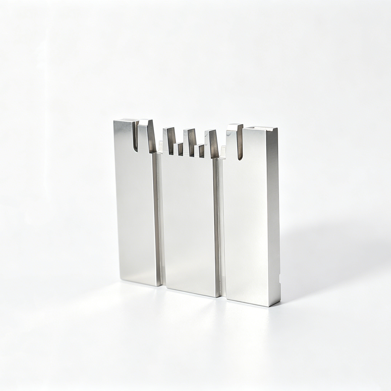
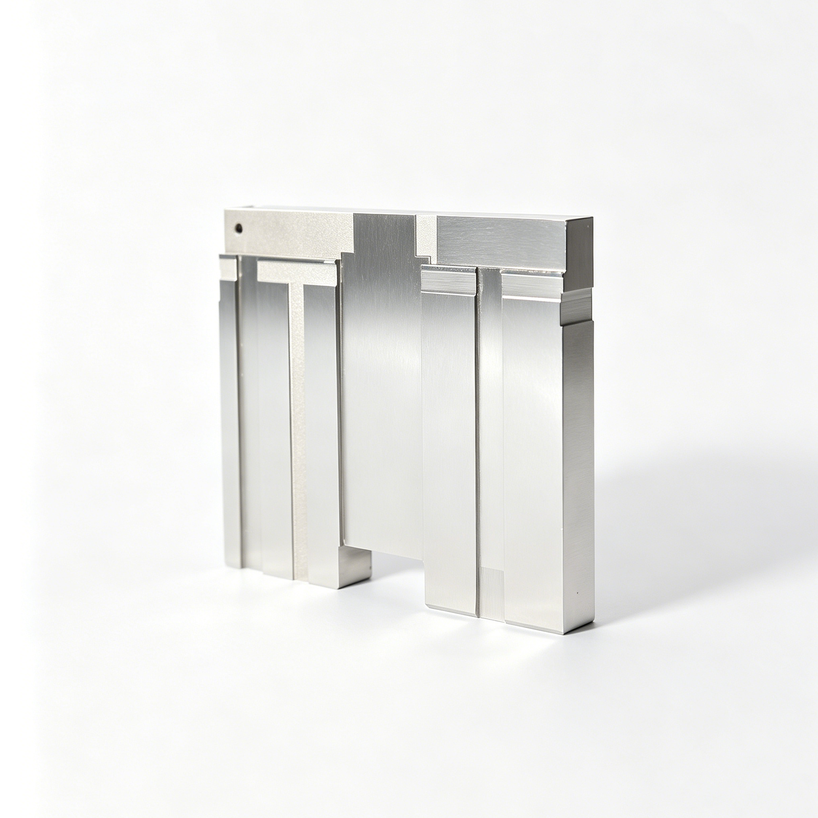
Representative Mold Maintenance and Replacement Components






Related Components and RFQ Options








Why Engineers Source Mold Maintenance and Replacement Components Through SUUXIANG
Drawing-led review and controlled manufacturing routes for maintenance, repair, and replacement tooling components.
Drawing-First Review
We review drawings, models, materials, quantities, and application context before aligning the proposed manufacturing route with your requirements.
Critical Dimensions Planned
Datum strategy, tolerance priorities, surface requirements, machining access, and grinding allowance are discussed before production commitments are made.
Integrated Process Routes
CNC machining, wire EDM, sinker EDM, precision grinding, fitting, and inspection are coordinated around the component’s functional features.
Wear-Part Replacement Focus
Replacement pins, inserts, slides, guides, and related components are evaluated against mating conditions, wear areas, and drawing-defined interfaces.
Inspection Matched to Requirements
Inspection planning follows the order’s critical dimensions and reporting needs, helping align measured evidence with the agreed quality expectations.
Revision Visibility Maintained
Clear revision, production, and delivery communication helps teams manage drawing changes and maintain traceability throughout the component workflow.
Product Families and Tooling Categories
Explore configurable precision-part families and process routes, then submit drawings, materials, critical dimensions, quantities, and inspection requirements for review.

CNC Machining Services
Precision CNC machining services for drawing-based custom parts, mold components, and tooling details. Process planning considers material condition, datums, critical dimensions, tool access, machining sequence, and the inspection evidence required before production is released.
Upload a Drawing
CNC Milling
Custom CNC milling services for prismatic, contoured, and multi-feature components. Drawing review addresses datum relationships, pocket access, wall geometry, thread requirements, machining allowance, and surface priorities so the route fits the part’s functional dimensions.
Upload a Drawing
CNC Turning
Precision CNC turning services for shafts, pins, sleeves, bushings, and rotational features. Review focuses on concentricity, runout, diameters, shoulder geometry, thread details, material condition, and any secondary milling, grinding, or inspection steps.
Upload a Drawing
5-Axis Machining
5-axis CNC machining for components with angled features, compound surfaces, or multiple critical faces requiring controlled setups. The machining strategy is evaluated against tool reach, fixturing, datum transfer, collision risk, surface requirements, and inspection access.
Upload a Drawing
Swiss & Micro Machining
Swiss machining and micro machining for small, slender, or detail-intensive parts where support, concentricity, and feature sequence matter. Provide drawings, material, tolerances, quantities, and functional context for a practical manufacturability review.
Upload a Drawing
Wire & Sinker EDM
Wire EDM and sinker EDM services for hardened features, narrow slots, internal profiles, sharp details, and geometries limited by conventional tool access. Process planning considers wire path or electrode strategy, recast-layer requirements, flushing, finishing, and inspection needs.
Upload a Drawing
Precision Grinding
Precision surface and profile grinding for controlled flatness, parallelism, profile form, and finishing stock on mold and die components. Grinding is planned with heat-treatment condition, datum strategy, allowance, accessibility, and final measurement method in view.
Upload a Drawing
Mold Core & Cavity Inserts
Precision mold core and cavity inserts manufactured from customer drawings and specifications. Reviews address steel selection, heat-treatment sequence, parting and shutoff geometry, cooling or feature access, EDM needs, grinding stock, and critical inspection points.
Upload a Drawing
Ejector & Ejection Components
Ejector pins, sleeves, and ejection components for mold assemblies where fit, wear behavior, alignment, and motion affect performance. Requirements should define diameters, lengths, hardness or treatment, clearance relationships, surface condition, and mating-component context.
Upload a Drawing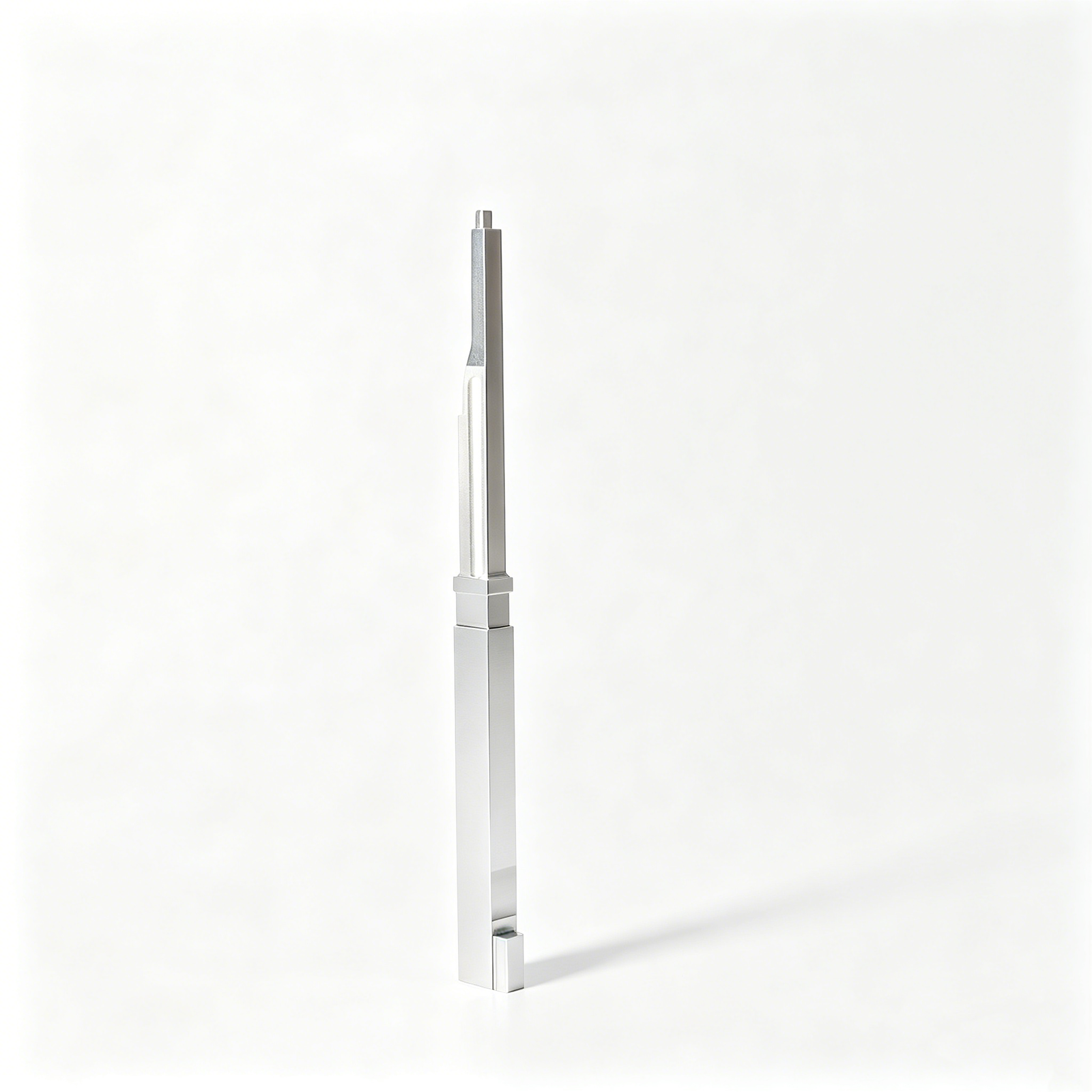
Core Pins, Guide & Locating Components
Core pins, guide pins, bushings, and locating components produced to drawing-defined functional relationships. SUUXIANG reviews fit class, datum reference, concentricity, alignment, material condition, surface needs, and whether grinding or EDM supports the required geometry.
Upload a Drawing
Slides, Lifters, Gates & Mold Accessories
Mold slides, lifters, gates, and accessories for configurable mold mechanisms and detailed inserts. Engineering review considers travel and mating relationships, wear surfaces, shutoff geometry, assembly access, heat treatment, lubrication needs, and critical dimensions.
Upload a Drawing
Connector Mold Components
Precision connector mold components for tooling where pin geometry, pitch, alignment, cavity detail, and wear control require disciplined process planning. Drawings should identify functional datums, material and hardness requirements, surface condition, and inspection expectations.
Upload a Drawing
Stamping Die Components
Precision stamping die components including punches, dies, guide elements, inserts, and formed details made to customer specifications. Review covers strip-related geometry, clearance, cutting edges, material and heat treatment, grinding sequence, EDM requirements, and dimensional control.
Upload a Drawing
Injection, MIM, CIM & Overmolding Tooling
Tooling and component work associated with injection molding, metal injection molding, ceramic injection molding, and overmolding within verified production scope. Project review addresses material behavior, interface geometry, tool access, finish, wear conditions, and inspection requirements.
Upload a Drawing
Machining Materials
CNC machining materials are selected against the drawing, application, machinability, strength, corrosion, wear, and heat-treatment requirements. Confirm exact grade, material condition, traceability needs, and any customer-specified source or documentation before release.
Upload a Drawing
Surface Finishes & Heat Treatment
Surface finishing and heat treatment are planned as part of the dimensional route, not as afterthoughts. Define required condition, hardness, coating or finish, masking concerns, post-treatment grinding allowance, surface priorities, and acceptance criteria in the RFQ.
Upload a Drawing
Quality, Metrology & Documentation
Precision inspection, metrology, and quality documentation are aligned to the approved drawing and inspection plan. Identify critical dimensions, datums, reporting format, sampling expectations, material records, revision status, and any required traceability before production begins.
Upload a Drawing
Prototyping & Low-Volume Production
Rapid prototyping and low-volume manufacturing for drawing-based parts that need disciplined review before repeatable production. Share the latest 2D and 3D data, material, quantity, target delivery date, dimensional priorities, surface needs, and inspection requirements.
Upload a DrawingMaterials for Mold Maintenance and Replacement Components

Pre-Hardened Tool Steel
A practical choice for mold plates, supports, and moderately loaded inserts where stable machining and balanced toughness are required. Delivered hardness and final heat-treatment requirements should be reviewed against drawing dimensions and service conditions.

Hardenable Tool Steel
Used for cores, cavity inserts, pins, and wear surfaces that require higher hardness after machining. Heat-treatment sequence, grinding stock, EDM condition, and critical-dimension inspection must be defined before production.

Stainless Tool Steel
Considered for tooling components exposed to humidity, corrosive resins, or long storage intervals. Corrosion resistance depends on the selected grade, heat treatment, surface condition, and the actual operating environment.

Powder Metallurgy Steel
Suitable for demanding wear applications involving filled resins, repeated sliding contact, or complex inserts. Material selection should account for toughness, finish requirements, EDM strategy, and the component’s expected maintenance cycle.

Copper Alloy Electrodes
Applied where conductive electrode material supports sinker EDM of detailed cavities, ribs, or inaccessible features. Grade selection, electrode wear allowance, finish target, and datum relationship should be aligned with the machining plan.
Manufacturing Processes for Mold Maintenance and Replacement Components

CNC Milling
CNC milling creates replacement inserts, slides, plates, and custom tooling features from drawing-controlled geometry. Tool access, datum selection, machining allowance, and surface requirements are reviewed to support practical downstream EDM, grinding, or fitting work.

CNC Turning
CNC turning produces rotational components such as core pins, sleeves, bushings, and locating elements. The route is planned around concentric features, functional diameters, material condition, and the dimensions that require inspection against the supplied drawing.

Wire EDM
Wire EDM forms precise through profiles, narrow slots, and hardened features where conventional tool access is limited. Wire path, start-hole access, datum relationship, and finishing allowance should be defined so the finished component supports its mating tooling interface.

Sinker EDM
Sinker EDM machines detailed cavities, ribs, corners, and internal features using planned electrodes. Electrode strategy, burn allowance, surface requirement, and critical geometry are reviewed with the drawing to coordinate EDM work with milling and final finishing.


Fitting and Inspection
Fitting and inspection verify component interfaces, critical dimensions, and drawing revision requirements before delivery. Measurement methods and reporting expectations are aligned to the order, helping teams assess mold maintenance and replacement components against their intended assembly function.
Mold Maintenance and Replacement Components for Tool Function

Locating Elements
Locating pins, bushings and datum features help establish repeatable alignment between mold plates, inserts or mating tooling. Define fit, positional tolerance, reference datum and service-access requirements so replacement parts preserve the intended assembly relationship.

Ejection Components
Ejector pins, sleeves, return elements and related parts support controlled part release. Drawing review should address clearance, bearing length, surface condition, hardness sequence and the features most likely to wear during repeated molding cycles.

Guide Components
Guide posts, guide bushings and wear-guiding details support predictable plate movement and alignment. Provide mating dimensions, lubrication provisions, running clearance and critical surface requirements to evaluate a suitable machining, grinding and inspection plan.

Slide Wear Parts
Slides, gibs, wear plates and related inserts manage guided side action in a mold. Their replacement design should consider contact surfaces, travel path, load direction, clearance, fastening access and any required fitting during tool maintenance.

Fastening Hardware
Custom fastening elements, dowels, retainers and mounting details secure replaceable components within the tool. Include thread specifications, engagement depth, counterbore geometry, assembly sequence and access constraints to reduce installation risk during maintenance.
About SUUXIANG Mold Maintenance and Replacement Components
SUUXIANG is the public-facing brand of Dongguan SuuXiang Precision Mold Co., Ltd., established in 2010 in Chang’an Town, Dongguan, Guangdong, China. We support global engineering, sourcing and quality teams with drawing-driven manufacturing for mold maintenance and replacement components, precision mold parts, connector tooling and custom machined work.
Our teams plan work around the drawing, critical dimensions, datum strategy, material and heat-treatment requirements, machining access and inspection needs. CNC machining, EDM, precision grinding, fitting and inspection are coordinated as an appropriate process route—not presented as a blanket promise for every specification or production volume.
What differentiates SUUXIANG is a practical, traceable approach to technical communication. Before quotation and production commitments, we review DFM risks, revision status, quality priorities and delivery requirements so buyers can align the component, inspection plan and documentation with the application.

Core Capabilities for Mold Maintenance and Replacement Components
DFM Before Replacement
Each replacement-part review begins with the controlled drawing, revision status, mating context, material requirement, and critical dimensions. This helps identify datum conflicts, inaccessible features, tolerance-stack risks, and service-fit concerns before quotation or production planning.
- Review 2D drawings and available 3D models
- Confirm datums, critical dimensions, and mating interfaces
- Flag tool-access and manufacturability constraints
- Align revision, quantity, inspection, and delivery requirements

CNC and EDM Routing
Mold maintenance and replacement components often require more than one machining method. SUUXIANG plans CNC milling or turning alongside wire EDM, sinker EDM, and multi-axis work when feature geometry, corner conditions, internal detail, or hardened material condition calls for it.
- Select processes around feature access and geometry
- Plan electrode strategy for EDM-required details
- Use wire paths for precise profiles and narrow features
- Coordinate machining sequence with heat-treatment requirements

Grinding and Fitting Control
Precision interfaces depend on controlled stock allowance and a practical finishing sequence. Grinding and fitting are considered against the part’s functional surfaces, sliding or locating relationship, and final assembly condition so removal steps do not compromise critical dimensions.
- Define grinding stock before finish machining
- Evaluate sliding, locating, and shutoff interfaces
- Protect functional surfaces through process sequencing
- Review fitting requirements with mating-component context

Inspection Planned Early
Inspection planning is tied to the drawing and agreed critical features, rather than added after machining. SUUXIANG can align measurement methods, reporting expectations, and traceability needs with the order so the final documentation reflects the verified inspection plan.
- Identify critical-to-quality dimensions before production
- Match inspection methods to feature and datum strategy
- Confirm reporting requirements with the RFQ
- Maintain visible revision and order documentation

Mold Maintenance and Replacement Components: Why Choose SUUXIANG
Compare evidence-led drawing review and controlled manufacturing communication with a typical quote-only supplier.
← Swipe left or right to view →
Mold Maintenance and Replacement Components: From Drawing Review to Delivery
A controlled workflow for custom replacement and maintenance components, aligned to critical dimensions, process access, inspection requirements, and revision-controlled delivery.
Review RFQ Package
We review drawings, models, material, quantity, application context, delivery target, and reporting needs to identify missing information before quotation or production planning.
Confirm DFM Priorities
Critical dimensions, datums, tolerance stack, surface requirements, machining access, heat-treatment sequence, and inspection methods are discussed to establish a practical manufacturing route.
Plan Process Route
The team assigns suitable CNC machining, EDM, grinding, fitting, and measurement steps, including electrode strategy, wire paths, grinding stock, and revision-control checkpoints.
Machine Critical Features
Components are produced through the approved process sequence, with controlled attention to dimensional priorities, surface condition, feature access, and any agreed heat-treatment requirements.
Inspect And Document
Finished parts are inspected against the order-specific plan. Measurement results, part identification, and required quality documentation are checked before release for packing.
Coordinate Delivery Release
Approved components are packed for shipment with revision and delivery information kept visible, supporting clear receipt checks and traceable coordination with your project team.
How to Source Mold Maintenance and Replacement Components
Provide the drawing, requirements, and quality priorities needed for a disciplined review before quotation.
Send Your Drawing Package
Send a 2D drawing and, when available, a 3D model. Identify revision status, datums, critical dimensions, surface requirements, and mating-component context for review.
Specify Material Requirements
Specify material, hardness or heat-treatment requirements, and any coating or surface-finish priorities. This lets the team assess process sequence, machining allowance, EDM needs, and grinding stock.
State Quantity and Timing
State the required quantity, application conditions, target delivery date, and any prototype or low-volume milestones. Flag risks that could affect component configuration, inspection, or coordination.
Define Inspection Expectations
Define inspection and reporting expectations before quotation, including measurement priorities, report format, traceability needs, and acceptance criteria. SUUXIANG aligns the review with documented order requirements.
Certificates and Quality Documentation
Mold Maintenance and Replacement Components: Approved Application Evidence
Verified customer feedback and project-specific outcomes will be published only when the customer has approved the statement and supporting documentation for public use.
Documented case evidence may include drawing revision control, inspection results, component fit confirmation, or delivery records when the applicable customer authorizes disclosure.
SUUXIANG does not publish unverified testimonials, anonymous performance figures, or claims about mold maintenance and replacement components without approved supporting evidence.
Mold Maintenance and Replacement Components: Evidence Publication Policy
Practical answers for engineering, sourcing, and quality teams preparing a drawing-led RFQ.
What files should I send for mold maintenance and replacement components?
Can SUUXIANG review mold maintenance and replacement components before quoting?
How do you manufacture mold maintenance and replacement components from a worn sample?
Is there a minimum order quantity for custom mold components?
Which materials and heat treatments can be considered?
Can I request an inspection report or first-article sample?
How should I plan lead time for a replacement component?
How are confidential drawings and IP-sensitive projects handled?
Buyer’s Guide to mold maintenance and replacement components
A practical decision framework for specifying replacement parts, evaluating supplier capability, controlling lifecycle costs, and avoiding sourcing errors that compromise mold performance, part quality, delivery continuity, and program risk.
1. What Are Mold Maintenance and Replacement Components?
Four categories define mold maintenance and replacement components: routine consumables, wear parts, repair parts, and engineered replacements. They serve injection molds, connector tooling, and stamping dies by restoring motion, sealing, alignment, cutting, ejection, or forming function without replacing the complete tool.
Two common routine-consumable examples are springs and seals; wear parts include ejector pins, bushings, guide elements, punches, and inserts exposed to friction, load, resin, or sheet contact. Repair parts address localized damage, while engineered replacements are drawing-controlled components recreated or revised to recover the original datum relationships, fits, and critical dimensions.
One replacement decision starts with measurement against the approved drawing, not visual appearance alone. Replace the component when wear, cracking, galling, distortion, or an unstable repair would compromise tolerance, mating action, part quality, or repeatable production; repair remains appropriate only when the restored feature can be verified and surrounding tool geometry is sound.
2. Evolution of Mold Maintenance and Replacement Components
Replacement work has evolved from local shop repair toward drawing-controlled manufacture. Today, 2D drawings, 3D models, CNC milling, wire EDM, sinker EDM, and precision grinding help teams reproduce released geometry, critical dimensions, material condition, and functional interfaces rather than merely copy a removed part.
Across global supply chains, three linked records matter: the approved drawing revision, inspection plan, and maintenance history. Preventive schedules based on cycles and observed condition help teams plan replacements before failure, while traceable RFQ data lets a supplier assess machining access, EDM strategy, grinding stock, and verification needs.
3. Types of Mold Maintenance and Replacement Components
Mold maintenance and replacement components should be classified by motion, sealing, forming, and thermal function. A replacement is viable only when its interfaces match the existing tool’s datum scheme and assembly stack.
| Family | Function and Failure Signs | Critical Drawing Inputs | Compatibility Concerns |
|---|---|---|---|
| Ejection and return | Release parts; sticking or bent pins | Diameter, length, fit, plate datum | Pin holes, return stroke, ejector layout |
| Guidance and forming | Align and form; flash or scoring | Datums, shutoff, cavity geometry | Guide locations, insert seat, steel condition |
| Slides and wear plates | Create side action; drag or galling | Travel, angles, wear faces, lubrication | Gib geometry, actuator and clearance |
| Cooling and hot-runner parts | Control temperature; leaks or imbalance | Port threads, channel layout, seal grooves | Manifold interface, connectors, pressure rating |
| Hardware and stamping-die items | Store force or cut/form; fatigue or burrs | Load, free length, punch-die clearance | Pocket dimensions, fastener threads, mating die |
Ejection And Return Parts
Ejector pins, sleeves, return pins, and plates release the molded part. Bent pins, galling, flash, or sticking indicate a fit, alignment, or lubrication review.
Guidance And Forming Components

Guide pins, bushes, cores, cavity inserts, and locating keys establish repeatable closure and part geometry. Wear appears as mismatch, flash, scoring, or unstable shutoff.
Motion Thermal And Die Items
Slides, wear plates, cooling parts, hot-runner interfaces, springs, seals, fasteners, punches, and dies require mating-component checks. Leakage, drag, fatigue, or burrs should be traced to the complete assembly.
4. Materials for Mold Maintenance and Replacement Components
Two selection questions govern mold maintenance and replacement components: what failure mechanism occurred, and which interface must remain stable. Material choice should follow resin, load, thermal path, finish, and service environment.
| Material Family | Primary Advantage | Typical Check |
|---|---|---|
| Pre-hardened steel | Machinability | Hardness and polish |
| Tool steel | Wear resistance | Heat-treatment distortion |
| Stainless steel | Corrosion resistance | Sliding wear |
| Bearing alloy | Low friction | Load and lubrication |
| Copper alloy | Heat transfer | Strength and safety |
| Carbide | Abrasive-wear resistance | Brittleness and support |
| Engineered polymer | Low-load isolation | Temperature and creep |
Steel Selection By Duty
P20-class pre-hardened steel supports practical machining and moderate-duty inserts; through-hardened tool steel better resists high-contact wear. Heat treatment must follow final stock-removal strategy to limit distortion.
H13 and other stainless grades suit moisture-prone tooling, but corrosion resistance does not replace hardness where sliding contact is severe.
Wear, Heat, And Finish
Glass-filled resins accelerate abrasive wear, making hardened steel, coatings, or carbide candidates for gates, cores, and high-wear edges. Coating compatibility depends on substrate hardness, adhesion, geometry, and required surface finish.
Beryllium-free copper alloys can improve local heat transfer; bearing alloys suit selected low-friction interfaces. Engineered polymers are limited to low-load guides, seals, or non-forming functions after temperature validation.
Validate Functional Equivalency
One material name is not an equivalency claim: supplier condition, hardness range, heat treatment, cleanliness, and finish can change service behavior. Compare the failed part’s function, mating material, load direction, lubricant, resin, and cooling exposure.
Three records should accompany a replacement decision: drawing revision, material certificate when required, and inspection plan. SUUXIANG can review these inputs against the requested manufacturing route.
5. Customization Options for Mold Maintenance and Replacement Components
Drawing-based mold maintenance and replacement components can be tailored to the actual tool stack, not merely a nominal catalog size. SUUXIANG reviews the drawing, mating context, and inspection expectations before confirming a process route.
Dimensions, Fits, And Surfaces
A 2D drawing should identify critical dimensions, datums, geometric tolerances, fit class, material, and required finish.
A mating component or assembly section helps distinguish a functional sliding, locating, or sealing fit from a noncritical dimension.
- Specify heat treatment and hardness requirements.
- Call out coatings and permitted buildup.
- Mark vent geometry and cooling features.
Changes Requiring DFM Review
A vent revision, cooling-channel change, tighter tolerance, or altered heat-treatment sequence can change tool access, EDM strategy, grinding stock, and distortion risk.
A coating or finish change also requires review where it affects fit, surface texture, or a mating face.
Identification, Kits, And Samples
An engraved part number, revision mark, or cavity identifier supports controlled replacement and service records.
A verified sample can support reverse engineering only when its wear state, mating dimensions, material evidence, and intended revision are confirmed; catalog replacements otherwise follow published standard geometry, while custom parts follow the approved drawing.
- Provide 3D model when available.
- State quantity and target date.
- Define inspection report requirements.
6. Quality Elements in Mold Maintenance and Replacement Components
A replacement part is interchangeable only when its functional interfaces are controlled against the installed tool’s datums. Define acceptance before machining, not after installation reveals flash, sticking, leakage, or misalignment.
Datum And Functional Dimensions
First, identify the mounting face, locating bore, and running axis as primary, secondary, and tertiary datums on the drawing.
Then, mark critical-to-function dimensions: shutoff geometry, pin-to-bore clearance, seal land, guide location, and mating-thread position.
Surface And Material Condition
Ra values, hardness range, effective hardened depth, and permissible edge break should be specified by each working surface.
Coating coverage must exclude or include defined fits deliberately; corrosion protection must not alter precision bores, threads, or sealing faces.
Inspection Evidence And Acceptance
100% inspection is appropriate for identified critical dimensions, concentricity, fit-class features, and functional threads when the drawing requires it.
Each record should identify revision, measuring method, datum reference, actual result, acceptance limit, material and heat-treatment evidence, and part traceability.
7. Choosing a Mold Maintenance and Replacement Components Supplier
A capable supplier evaluates the failed component against its drawing, mating geometry, and service conditions before quoting. For mold maintenance and replacement components, evidence and revision discipline matter as much as machining access.
| Evaluation Area | Required Evidence | Buyer Check |
|---|---|---|
| Engineering | DFM and process route | CTQs and datums reviewed |
| Quality | Material, heat treatment, inspection | Records tied to revision |
| Execution | Capacity, packaging, communication | Milestones and escalation defined |
Engineering And Revision Review
Before RFQ release, require a drawing review covering CTQ dimensions, datums, tool access, EDM or grinding route, and revision status.
Ask: Which file revision controls production, and how will deviations or clarification requests be recorded?
Traceability And First Article
Before first-article approval, match material certificates, heat-treatment records, and inspection results to the purchase order and part revision.
Ask: Which dimensions are measured, by which method, and what sample-approval record releases production?
Delivery And Application Fit
For connector molds or stamping dies, assess proven understanding of small features, wear interfaces, fitting, and protective packaging.
Ask: What capacity constraints affect the date, who owns status communication, and how are transit damage and late changes handled?
8. Common Buyer Mistakes With Mold Replacement Parts
Replacement parts fail most often at the interface, not at the quoted nominal size. For mold maintenance and replacement components, controls should move from the RFQ into the purchase order and receiving plan.
Incomplete Drawing Packages
2D drawings without datums, tolerances, mating context, or revision status invite assumptions. The result can be an unassemblable insert or delayed rework; attach the model, critical dimensions, and controlled drawing revision.
Nominal Size And Fit
One matching outside diameter does not establish a working fit. Specify datum references, clearance or interference targets, mating-part dimensions, and functional travel so the supplier can plan machining, EDM, and grinding.
Material And Surface Controls
Material substitutions without approval can change wear, corrosion behavior, or heat-treatment response. State material grade, approved alternatives, hardness range, surface finish, coating requirements, and required certificates on the PO.
Revision, Receipt, And Cost
One mixed revision can create a misleading assembly failure, while unchecked receipts can put nonconforming parts into a tool. Require part marking or packaging identification, incoming checks against CTQs, inspection records, and a total-cost review covering downtime and rework.
9. Launching a Replacement-Component Sourcing Program
A replacement program starts with the actual tool asset, not a generic spare-parts list. Engineering, maintenance, quality, procurement, and program management should agree on ownership before an RFQ is released.
Review And Rank Assets
An asset register should link each mold ID, revision, cycle history, failure mode, and installed component. Maintenance can rank parts by production-stop risk, replacement frequency, and interchangeability.
- Hold safety stock for unique, long-lead, production-stopping parts.
- Make to order for stable, noncritical parts with verified drawings.
Clean Drawings And Approve First Articles
2D drawings should define datum references, critical dimensions, material, heat treatment, surface requirements, and revision status. Quality approves a sample or first article against an agreed inspection plan before recurring supply.
Control Reorders And Records
Each approved part needs a supplier record, packing identification, inspection requirement, and reorder trigger. Program management reviews consumption and lead-time changes; maintenance logs each replacement against mold ID, cycle count, and failure observation.
10. Pricing Mold Maintenance and Replacement Components
Drawing review is required before a supplier-specific quotation: geometry, tool access, datum scheme, material condition, tolerance, heat treatment, coating, and inspection plan determine both route and risk. SUUXIANG should quote only against the current drawing revision and agreed technical evidence.
Three cost layers commonly govern mold maintenance and replacement components: one-time programming and fixturing, unit machining and finishing, and verification or logistics. Tight positional relationships, EDM electrodes, grinding, post-heat-treatment finishing, special coatings, CMM reporting, and expedited scheduling can raise both cost and lead-time exposure.
Two total-cost checks matter beyond piece price: estimate downtime cost if the component fails and compare it with holding a controlled spare. Define traceability, inspection records, packaging, and revision identification before release; an inexpensive unverified spare can extend a shutdown.
| Representative order tier | Cost behavior | Typical lead-time driver |
|---|---|---|
| 1–2 pieces | Setup dominates; complex geometry magnifies risk | DFM clarification, material availability, programming |
| 3–10 pieces | Setup spreads across units; inspection scope remains important | EDM or grinding sequence, heat treatment |
| 11+ pieces | Repeatable fixtures may reduce unit cost | Capacity, batch inspection, agreed delivery split |
Upload Drawings for Mold Maintenance and Replacement Components
Include material, quantity, critical dimensions, inspection requirements, and target delivery date for a focused drawing review and RFQ discussion.