
Mold Return Pins, Reviewed Before Machining
Send your drawing for mold return pins with critical dimensions, material, quantity, and inspection requirements for a disciplined DFM and quotation review.
Representative Mold Return Pin and Tooling Components


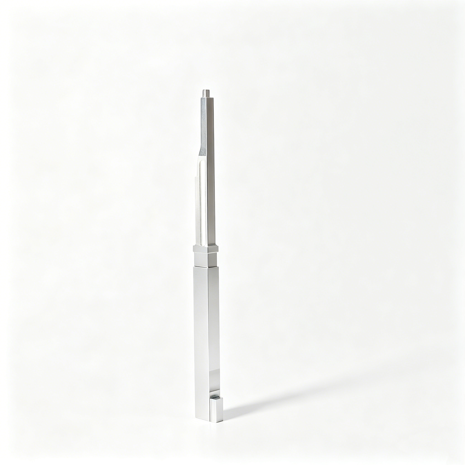


Related Mold Components for Quotation





Why Choose Our Mold Return Pins Workflow
Drawing-led review aligns process decisions, inspection priorities, and revision control before production commitments.
DFM Before Quotation
We review drawing clarity, application context, tool access, and manufacturability questions before defining a practical quotation route.
Critical Dimensions Planned
Critical-to-quality dimensions, datums, fit requirements, and surface priorities are identified to support a focused manufacturing and inspection plan.
Process Route Selection
CNC machining, EDM, grinding, and fitting are considered together according to geometry, material condition, access, and finishing requirements.
Inspection Method Alignment
Inspection expectations are discussed against the drawing so documentation and measurement methods match the agreed order requirements.
Visible Revision Control
Drawing revisions and project changes stay visible throughout coordination, helping prevent outdated requirements from reaching the manufacturing floor.
Drawing-Led Communication
SUUXIANG keeps material, quantity, delivery, and quality requirements connected to the mold return pins inquiry from review through delivery.
Return Pins and Precision Component Families
Drawing-driven process routes for return-pin assemblies, mold components, and related precision tooling work, reviewed against material, critical dimensions, and inspection requirements.

CNC Machining Services
Precision CNC machining services for custom return pins and associated mold components, planned from the drawing, material condition, critical dimensions, and quantity. CNC, EDM, grinding, fitting, and inspection are selected according to verified project requirements.
Upload a Drawing
CNC Milling
Custom CNC milling services support flats, pockets, mounting features, guide structures, and mating faces on return-pin plates and related tooling components. Tool access, datum setup, stock allowance, and post-machining finishing requirements should be reviewed before production.
Upload a Drawing
CNC Turning
Precision CNC turning services produce rotational features such as return-pin bodies, shoulders, steps, and locating diameters. The process route should account for concentricity, surface requirements, material condition, heat-treatment sequence, and any subsequent grinding.
Upload a Drawing
5-Axis Machining
5-axis CNC machining supports complex component geometry where multiple faces, compound angles, or restricted tool access affect setup strategy. For mold and return-pin projects, feasibility depends on the drawing, workholding, critical features, material, and required inspection method.
Upload a Drawing
Swiss & Micro Machining
Swiss machining and micro machining address small-diameter pins, slender features, and compact connector-tooling details where rigidity and handling matter. Drawing review should identify length-to-diameter concerns, tolerances, cutoff conditions, and measurement access.
Upload a Drawing
Wire & Sinker EDM
Wire EDM and sinker EDM services support hardened profiles, narrow slots, internal geometry, and features unsuitable for conventional cutting alone. Electrode strategy, wire path, recast-layer considerations, finish requirements, and datum relationships require project-specific review.
Upload a Drawing
Precision Grinding
Precision surface and profile grinding establishes controlled faces, diameters, profiles, and fit-critical surfaces on hardened mold components. Grinding stock, heat-treatment distortion, datum control, surface requirements, and inspection points should be defined before machining begins.
Upload a Drawing
Mold Core & Cavity Inserts
Precision mold core and cavity inserts are configured from customer drawings for molding geometry, shutoff regions, cooling interfaces, and mating conditions. Material, heat treatment, EDM requirements, machining allowances, and inspection expectations determine the production route.
Upload a Drawing
Ejector & Ejection Components
Ejector pins, sleeves, and ejection components include drawing-based parts used to guide, return, or eject molded parts. Fit with mating plates, diameter control, shoulder geometry, hardness, surface condition, and return-pin interface requirements should be specified in the RFQ.
Upload a Drawing
Core Pins, Guide & Locating Components
Core pins, guide pins, and locating components are produced as configurable precision parts for alignment, feature formation, and repeatable assembly. Critical diameters, engagement lengths, datum relationships, material condition, and mating-component details help define a practical process plan.
Upload a Drawing
Slides, Lifters, Gates & Mold Accessories
Mold slides, lifters, gates, and accessories cover drawing-based mechanisms and supporting components that require controlled travel, fit, wear surfaces, and assembly interfaces. Feasibility depends on geometry, material, heat treatment, lubrication needs, and inspection criteria.
Upload a Drawing
Connector Mold Components
Precision connector mold components support tooling features for fine-pitch connector products and related molded interfaces. Small details, insert alignment, cavity geometry, material selection, EDM strategy, and inspection access must be reviewed against the drawing and mating context.
Upload a Drawing
Stamping Die Components
Precision stamping die components are manufactured for die sets, forming, cutting, guiding, and locating functions within verified project scope. Material grade, heat-treatment sequence, edge condition, clearance-related features, grinding requirements, and assembly datums should be provided.
Upload a Drawing
Injection, MIM, CIM & Overmolding Tooling
Injection, MIM, CIM, and overmolding tooling components are supported when requirements fall within SUUXIANG’s verified production scope. Drawings should identify molded material context, critical interfaces, venting or gate features, insert conditions, and required documentation.
Upload a Drawing
Machining Materials
CNC machining materials are selected against the drawing, functional load, wear condition, corrosion exposure, machinability, and any specified heat treatment. Material availability, certification needs, and substitution rules should be confirmed before production commitment.
Upload a Drawing
Surface Finishes & Heat Treatment
Surface finishing and heat treatment are planned around wear resistance, corrosion protection, friction, appearance, dimensional stability, and mating behavior. Coating or treatment specifications, masking needs, pre- and post-treatment dimensions, and verification requirements should accompany the drawing.
Upload a Drawing
Quality, Metrology & Documentation
Precision inspection, metrology, and quality documentation are aligned with the order’s critical dimensions, datums, surface requirements, and reporting needs. Agree the inspection plan, sampling expectations, revision level, traceability needs, and required records before production begins.
Upload a Drawing
Prototyping & Low-Volume Production
Rapid prototyping and low-volume manufacturing support drawing-based evaluation, tooling validation, replacement components, and controlled production runs. Quantity, revision maturity, material, critical features, delivery target, and inspection requirements determine the appropriate manufacturing route.
Upload a DrawingMaterials Considered for Mold Return Pins

Tool Steel
A practical option for mold return pins requiring wear resistance and stable geometry through repeated ejector-system movement. Grade, heat-treatment condition, grinding allowance, and mating-surface requirements should be defined from the drawing.

Stainless Steel
Considered where moisture, resin byproducts, storage conditions, or process environments raise corrosion concerns. Stainless grade selection must also account for required hardness, machining response, surface finish, and contact conditions.

Alloy Steel
Often evaluated when a project needs a balance of core strength, toughness, and heat-treatment flexibility. The specification should identify hardness targets, dimensional priorities, coating needs, and the return pin’s mating components.

Bearing Steel
May suit return-pin applications where repeated sliding contact and wear behavior are central considerations. Material suitability depends on the specified heat treatment, surface condition, lubrication approach, geometry, and inspection plan.

Pre-Hardened Steel
Can be reviewed for projects that need a defined starting hardness and controlled machining route. Confirm the exact grade, required finish, critical dimensions, grinding stock, and any downstream treatment before quotation.
Mold Return Pins: Supported Machining and Finishing Processes

CNC Turning
CNC turning establishes cylindrical diameters, shoulders, head forms and reference features for mold return pins. Process planning considers datum locations, stock condition and machining allowance so downstream grinding or EDM can protect critical geometry.

CNC Milling
CNC milling produces flats, drive features, reliefs, mounting details and custom interfaces specified on drawing-based components. Tool access, clamping strategy and tolerance relationships are reviewed early to reduce avoidable rework during fitting.

Wire EDM
Wire EDM is considered for narrow profiles, precision slots and features requiring controlled wire paths after heat treatment. The route is evaluated against corner requirements, datum strategy and the drawing’s allowable finish and dimensional conditions.

Sinker EDM
Sinker EDM supports detailed formed features or inaccessible internal geometry where conventional cutting tools cannot reach effectively. Electrode strategy, spark allowance and subsequent inspection requirements are defined against the approved drawing and revision.


Fitting And Inspection
Fitting and inspection verify that mold return pins and mating features align with the specified functional relationship. Measurement methods, critical dimensions, reporting needs and revision status are coordinated so final documentation matches the agreed inspection plan.
Mold Return Pins and Complementary Components

Guide Pins
Guide pins establish repeatable alignment between mold plates during closing. Review diameter, engagement length, fit with guide bushings, lubrication provisions and any relationship to mold return pins before releasing the component set.

Locating Components
Locating rings, keys and precision dowels help establish the mold’s machine and plate references. Provide datum relationships, mounting features and mating-part details so the locating scheme can be assessed alongside critical mold dimensions.

Ejector Pins
Ejector pins transfer force to release the molded part and must return without interference. Share pin layout, plate thickness, stroke, surface requirements and contact conditions when reviewing return-pin and ejector-system interfaces.

Support Pillars
Support pillars reinforce plate areas subject to clamp and injection loads. Their diameter, height, contact faces and positional relationship to ejector plates should be reviewed with return-pin locations to preserve clearance and load paths.

Fastening Elements
Screws, dowels and threaded retention features secure mold plates and precision inserts. Include thread specifications, counterbores, access constraints and assembly sequence so machining, fitting and inspection can follow the approved drawing.
About SUUXIANG Precision Manufacturing
SUUXIANG is the sole public-facing brand of Dongguan SuuXiang Precision Mold Co., Ltd., established in 2010 in Chang’an Town, Dongguan, Guangdong, China. Founded by XiaoCheng Huang, the company helps global engineering, sourcing and quality teams convert drawings and specifications into inspected custom CNC parts, precision mold components, connector tooling and die components.
For mold return pins and related tooling parts, our drawing-driven workflow brings together CNC milling and turning, multi-axis machining, EDM, precision grinding, fitting and inspection. Before quotation or production commitments, we review critical dimensions, datums, material and heat-treatment requirements, machining access, surface needs and inspection expectations.
What distinguishes SUUXIANG is disciplined project coordination around manufacturability, revision control and traceable quality evidence. Rather than presenting a fixed catalog as the answer to every requirement, we align the process route and inspection plan to the approved drawing, application context, quantity and delivery needs.

Core Capabilities for Mold Return Pins
DFM and Datum Review
SUUXIANG reviews mold return pin drawings before quotation to clarify functional datums, critical diameters, seating interfaces, stroke-related clearance, material requirements, and revision status. This early review helps align machining and inspection planning with the mold assembly’s actual locating and return requirements.
- Identify critical-to-quality dimensions and datum references
- Review mating surfaces, counterbores, and installation interfaces
- Clarify material, heat-treatment, and surface requirements
- Record drawing revisions before production planning

CNC, EDM, and Grinding Strategy
The process route for mold return pins is selected from the drawing rather than assumed from a generic part family. CNC machining, EDM, and precision grinding can be combined where geometry, hardness sequence, access, surface requirements, and dimensional priorities justify each operation.
- Match machining routes to geometry and tool access
- Assess wire-EDM or electrode needs for nonstandard features
- Plan heat-treatment sequence and finishing operations
- Preserve suitable stock for final grinding

Allowance and Fitting Control
Return performance depends on more than a nominal diameter. SUUXIANG evaluates grinding allowance, mating-component conditions, edge requirements, and assembly context so the final part can be finished against the applicable drawing requirements instead of relying on unverified standard assumptions.
- Confirm grinding stock before final-size operations
- Review fit-sensitive diameters and bearing surfaces
- Consider burr control and edge-break requirements
- Request mating-part context when it affects fit

Inspection and Revision Traceability
Inspection planning is tied to the order’s confirmed critical dimensions, tolerances, and reporting needs. SUUXIANG keeps drawing revisions and delivery information visible through the project workflow, then prepares final documentation to match the agreed inspection plan and supplied order requirements.
- Define inspection methods for critical features
- Align requested reports with the approved drawing
- Maintain visible revision-control information
- Confirm documentation needs with the RFQ

Why Source Mold Return Pins from SUUXIANG?
Compare a controlled, drawing-led workflow with generic quoting across the decisions that affect fit, inspection, and delivery.
← Swipe left or right to view →
Mold Return Pins: From Drawing Review to Shipment
A controlled workflow aligns critical dimensions, process choices, inspection requirements, and revision details before production and delivery coordination.
Review Drawings and Requirements
We review 2D drawings, available 3D models, quantities, application context, critical dimensions, datums, surface requirements, delivery targets, and requested inspection documentation.
Plan Material and Process
The project discussion confirms material and heat-treatment requirements, machining access, tolerance priorities, grinding allowance, and whether CNC machining, EDM, grinding, or fitting is appropriate.
Machine Critical Features
Production follows the agreed route, using applicable CNC milling, turning, multi-axis machining, wire EDM, sinker EDM, and precision grinding processes for the specified return-pin geometry.
Inspect and Control Revisions
Inspection is planned around agreed critical dimensions and measurement methods, while drawing revisions, process information, and quality records remain linked to the current order.
Pack and Coordinate Delivery
Completed mold return pins are prepared according to the verified order requirements, with packing, final documentation, and shipment coordination aligned to the agreed delivery plan.
Work with SUUXIANG on Mold Return Pins
Provide complete technical inputs early so the proposed manufacturing route, inspection plan and quotation reflect your actual mold-return-pin requirements.
Send Your Drawing Package
Submit the 2D drawing and available 3D model for mold return pins, including revision status, application context, mating details and any relevant assembly constraints.
Define Material and Quantity
Identify the required material, heat-treatment condition, quantity and target delivery date so SUUXIANG can assess a suitable process route and project coordination needs.
Identify Critical Requirements
Flag critical dimensions, datums, surface requirements, fit conditions and tolerance priorities. Note where machining access, grinding stock, EDM strategy or traceability affects the part.
Confirm Inspection Expectations
Specify measurement methods, reporting requirements, sampling expectations and documentation needed with delivery. These inputs support an inspection plan aligned with the drawing and order.
Review the Proposed Plan
Review DFM feedback, manufacturability questions, quotation scope and revision details before production commitments. Resolve open technical points before releasing the work for manufacture.
Mold Return Pins: Certifications and Quality Documentation
Mold Return Pins Customer Project Feedback
Customer testimonial pending written approval. Publish only after the project scope, verified outcome, and authorized customer attribution have been confirmed.
Customer testimonial pending written approval. Publish only after the project scope, verified outcome, and authorized customer attribution have been confirmed.
Customer testimonial pending written approval. Publish only after the project scope, verified outcome, and authorized customer attribution have been confirmed.
Customer References and Project Feedback
Practical answers for drawing-led sourcing, inspection planning, and controlled production discussions.
What information do you need to quote mold return pins?
Is there a minimum order quantity for custom mold return pins?
Can you provide samples before a larger mold return pin order?
Which materials and heat treatments can be considered?
How should I plan lead time for custom mold return pins?
What inspection reports are available for mold return pins?
How are mold return pins packaged and shipped internationally?
How do you protect drawings and project IP?
The Complete Buyer’s Guide to mold return pins
A practical framework for specifying mold return pins, evaluating drawing-based suppliers, comparing materials and designs, controlling quality risks, and avoiding sourcing mistakes that cause wear, misalignment, rework, or delayed tool launches.
1. What Are mold return pins?
In a two-plate injection mold, mold return pins are fixed to the moving-side ejector assembly and push against return-pin contact pads or the cavity-side surface as the mold closes. Their job is to drive the ejector plate back to its fully retracted position after the part has been ejected (https://www.fengzhou168.com/en-US/newsc15-return-pin-essential-component-for-mold-efficiency).
After ejection, the machine begins closing while ejector pins may still project into the molding area. Return pins contact first, move the ejector plate rearward, and retract the ejector pins before the mold halves reach their closing condition; this prevents pin-to-cavity or pin-to-parting-surface interference.
Three roles must remain distinct: ejector pins contact and release the molded part; guide pins align mold halves; stop pins set a mechanical travel or support limit. Mold return pins reset the ejector system, so their length, contact face, mounting datum, and wear condition directly affect repeatable closing, uninterrupted cycling, and protection against costly collision damage.
2. Evolution of mold return pins
In early production molds, return members were commonly made in the toolroom to suit one mold base and its ejector travel. As cycle counts and interchangeability expectations increased, purchasers needed more than a nominal diameter: bearing length, head geometry, mating holes, hardness condition, and installation datum became controlled requirements.
By the catalog era, standardized mold-component suppliers offered selectable diameters and configurable lengths; MISUMI, for example, lists a medium-to-large return-pin series with length configurable in 0.1 mm (https://us.misumi-ec.com/vona2/maker/misumi/mold/K0700000000/K0701000000/K0701060000). This reduced routine sourcing time, but did not remove the need to verify stack height, travel, clearance, and the return member’s contact condition on the actual mold drawing.
Today, a catalog part is practical when its geometry and material condition match the released design. A drawing-based custom part is the safer route when stepped profiles, nonstandard heads, special fits, controlled heat-treatment sequence, EDM features, or inspection reporting affect mold function.
3. Types of mold return pins
Three mounting decisions govern return-pin selection: head retention, working clearance, and removal access. Choose the configuration from the ejector-plate stack, not diameter alone.
| Configuration | Mounting Method | Clearance And Serviceability | Best Fit |
|---|---|---|---|
| Headed | Counterbored head | Head pocket; accessible removal | Conventional retained installation |
| Straight or shoulder | Bore or stepped seat | Running clearance; shoulder stop | Simple or controlled stack-up |
| Tapped end | Threaded extraction feature | Tool access for removal | Blind or difficult service locations |
| Custom drawing | Specified geometry | Defined on drawing and inspection plan | Unique stack, access, or locating needs |
Headed Return Pins
A headed pin seats in a counterbore and positively retains the pin against ejector-side load. Specify head clearance and a removal path before fixing plate thickness.
Straight And Shoulder Styles
A straight pin relies on its fit and end location; a shoulder establishes a controlled axial stop. Use shoulders where stack height or return position needs repeatable definition.
Tapped And Custom Designs
A tapped end permits extraction when blind mounting blocks access. Custom geometry is justified for nonstandard stack-ups, interference constraints, defined locating features, or service requirements that catalog parts cannot document.
4. Materials and heat treatment
Three families usually frame selection: pre-hardening tool steels, through-hardening tool steels, and stainless grades. Match the choice to load, sliding wear, coolant exposure, toughness, and post-treatment dimensional movement.
| Material Family | Typical Strength | Best Selection Factor |
|---|---|---|
| P20-type tool steel | Pre-hardened | Machinability and stability |
| H13-type tool steel | Heat treated | Wear with toughness |
| Stainless steel | Grade dependent | Corrosion exposure |
Material Family Comparison
AISI P20 suits moderate-duty components where machinability and stable pre-hardened condition matter. H13-type steel better balances hot-strength, toughness, and wear resistance; stainless is considered where water or humid storage raises corrosion risk.
Selection By Service Condition
Two contact conditions drive the decision: repeated sliding and impact at return. Specify the mating bore, lubrication or coolant exposure, expected cycles, and any risk of side loading; hardness alone does not establish service life.
Drawing Treatment Requirements
0.01 mm-scale fit requirements can be altered by heat treatment and finish operations. State material standard, target hardness range, heat-treatment sequence, grinding allowance, surface finish, critical datums, and inspection method; confirm any coating after evaluating adhesion and dimensional effect.
5. Custom mold return pins from drawings
A manufacturable RFQ converts functional intent into dimensions, datums, and acceptance evidence. For custom mold return pins, a drawing review should resolve unspecified interfaces before material is cut.
Define The Functional Geometry

Record nominal diameter, overall length, working length, head diameter, head thickness, and seating datum. Identify mating bores, counterbores, plate thicknesses, and clearance conditions so the functional travel is unambiguous.
- Special end profile or radius
- Shoulder location and diameter
- Thread size, pitch, class, and depth
Set Critical Requirements
Assign tolerances to diameter, length, concentricity, and runout only where function requires control. State material, heat-treatment condition, hardness requirement, surface finish, and any coating or corrosion requirement on the drawing or specification.
- Identify critical-to-quality dimensions
- Define datum references for inspection
- Specify required report or measurement method
Close The RFQ Gaps
Include quantity, revision level, 2D drawing, and 3D model when available. Request review of tool access, turning sequence, grinding allowance, EDM needs, markings, protective packaging, and delivery target before production approval.
- Part or cavity identification marking
- Individual sleeves or compartmented packaging
- First-article and final-inspection expectations
6. Construction and quality checkpoints
Two functional interfaces govern return-pin reliability: the shank-to-bore fit and the head-to-ejector-plate contact. Drawing review should define datums, limits, finish, hardness sequence, and inspection method before machining begins.
Shank Geometry And Bore Fit

Diameter, straightness, and concentricity should be measured from the specified functional datum, not from an arbitrary chucking surface. A bent or eccentric shank can side-load the bore, promote galling, and make ejector-plate return inconsistent.
Surface roughness must suit the bore and lubrication condition; a visually smooth part may still carry directional grinding marks. Incoming inspection should check diameter at multiple axial locations and verify runout over the functional length.
Head, Threads, And Edges
Head-to-shank transition radii, head flatness, and burr removal determine how evenly the return pin contacts the ejector plate. A sharp transition or raised burr can initiate wear, tilt the plate, or damage the mating counterbore.
Thread form, engagement length, and chamfers require drawing-specific verification when threaded ends are used. Incoming checks should include go/no-go thread gauging where specified and tactile inspection for damaged starts.
Heat Treatment And Handling
Heat-treatment consistency must be reviewed with the specified hardness, case-depth requirement, and sequence relative to grinding. Uneven hardness or inadequate finish stock can reduce wear life or alter final size after finishing.
Protected packing matters because dents, corrosion, and head-edge impacts can compromise alignment before assembly. Receiving inspection should compare revision, material evidence, inspection report, and part marking with the purchase order.
7. Choosing a mold return pin supplier
Two documents—an approved drawing package and inspection plan—should anchor supplier evaluation. Ask for project-specific evidence rather than accepting general capability statements.
| Evaluation Area | Evidence To Request | Marketing Claim To Question |
|---|---|---|
| Drawing review | Marked-up DFM and revision acknowledgement | We understand every drawing |
| Quality control | Traceable report and measurement method | 100% precision guaranteed |
| Delivery control | Milestone schedule and packaging plan | Fast delivery available |
Review The Drawing Process
One formal review should identify datums, critical dimensions, fit, EDM or grinding access, and heat-treatment sequence. Request marked-up DFM feedback, open questions, and revision-controlled acknowledgement.
Verify Process Evidence
A first-article plan should state material traceability when required, machining route, heat-treatment records, measuring method, and acceptance criteria. Request sample reports tied to actual dimensions, not a generic certificate.
Test Delivery Discipline
One written schedule should separate drawing approval, material release, first article, production, inspection, and dispatch. Confirm export packaging, communication cadence, deviation handling, and corrective-action response before issuing the order.
8. Common mold return pin sourcing mistakes
Eight sourcing errors recur when mold return pins are released from incomplete drawings. Each can turn a low-cost component into ejector-system damage, unplanned fitting, or delayed mold trials.
Specify The Functional Envelope
Nominal diameter alone does not define fit. State installed length, working length, stroke, head geometry, and the return position; otherwise the ejector plate may bottom early or fail to reset.
One release question matters: what travel remains at full ejection and at mold close? Include the mating drawing section and relevant datums.
Match Interfaces And Duty
Hardness is not a standalone requirement. Match material and heat-treatment condition to cycle duty, impact loading, lubrication, and the mating-hole condition; a poor pairing can gall, wear, or indent the contact surface.
Threads also carry functional risk. Define thread size, depth, class, engagement, and access, then ask whether assembly and removal tools clear adjacent mold features.
Release Measurable Acceptance Criteria
Critical dimensions require a stack-up review across the pin, plate, bore, and closing reference. Ignoring accumulated variation can create binding, insufficient return, or inconsistent contact.
Inspection criteria must name dimensions, datums, method, sample quantity, and reporting need. Ask which features are critical-to-quality and what evidence is required before shipment.
Unit price should be compared only after the same scope is quoted. Confirm whether material traceability, heat treatment, grinding, inspection, revision control, packaging, and delivery assumptions are included.
9. From RFQ to production approval
One complete RFQ should include the 2D drawing, 3D model when available, quantity, mold application, mating conditions, material, heat treatment, critical dimensions, and reporting requirements. SUUXIANG can use that package to frame a controlled drawing review before routing work.
Confirm The Process Route
First, confirm datums, toleranced diameters, head geometry, hardness sequence, grinding stock, and any EDM access limitations.
Second, resolve unclear surface-callout or fit requirements in writing; prototype orders should prioritize learning-critical features before quantity optimization.
Approve Evidence Before Release
For a first article, agree whether approval requires a sample, dimensional inspection record, material evidence, or a combination.
For low-volume lots, link the agreed inspection method to identified critical dimensions and retain records with the order revision.
Control Revision And Start-Up
Before production release, identify one drawing revision, approved deviations, packing protection, part identification, and delivery quantity.
During initial mold use, record fit, return action, wear observations, and any change request; repeat orders should reference the approved revision and prior inspection plan.
10. mold return pins pricing and cost
2 cost stages determine mold return pins spend: one-time drawing review, process planning and any dedicated setup, followed by recurring machining, treatment, finishing and inspection cost. Request a quotation when geometry differs from standard catalog form or when the drawing assigns critical datums, tolerances or surface requirements.
1 consolidated purchase order can reduce total landed cost by sharing material purchasing, heat-treatment batches, inspection planning and freight across compatible parts. Include quantity, material and heat-treatment callouts, required reports, revision level and target date so SUUXIANG can confirm a process route within verified scope.
| Quantity tier | Complexity and material level | Inspection requirement | Indicative lead-time driver |
|---|---|---|---|
| Prototype: 1–10 | Custom geometry, tool steel or specified heat treatment | Critical dimensions or first-article report | Programming, setup and external-process coordination |
| Low volume: 11–50 | Stepped form, EDM features or finish requirements | Sampled dimensional report | Batch size, EDM and grinding sequence |
| Repeat batch: 51–200 | Stable drawing and confirmed material route | Agreed sampling plan | Material availability and scheduled production slots |
| Consolidated order: 200+ or mixed parts | Shared blanks; separate operations where needed | Part-specific traceability and records | Batching, document package and shipment planning |
Upload Your Drawing for a Mold Return Pin Quote
Send drawings, material, quantity, critical dimensions, inspection requirements, and target delivery date for a disciplined SUUXIANG project review.