
Multi-Slot Connector Mold Cores, Reviewed Before Machining
SUUXIANG turns drawings for multi-slot connector mold cores into inspected components through DFM, CNC machining, EDM, grinding, and planned inspection.
Representative Components for Multi-Slot Connector Mold Core Development





Related Product Catalogue and Quotation


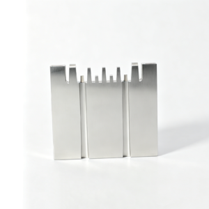


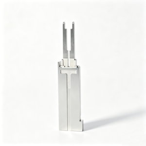



Engineering Advantages for Multi-Slot Connector Mold Cores
A disciplined review and manufacturing route keeps critical connector-tooling requirements visible from drawing evaluation through final inspection.
Drawing Review First
We review drawings, models, material requirements, quantities, and application context to identify manufacturability questions before quotation or production planning.
Critical Dimensions Planned
Critical-to-quality dimensions, datums, tolerance stacks, surface requirements, and mating features are clarified to support an appropriate machining and inspection approach.
Coordinated Process Routes
CNC machining, wire EDM, sinker EDM, grinding, and fitting are planned around tool access, electrode strategy, wire paths, and machining allowance.
Inspection Method Alignment
Inspection expectations are defined against the drawing and order requirements, including measurement priorities, reporting needs, and traceability documentation.
Revision Control Visible
Drawing revisions and project changes remain visible during coordination, helping prevent outdated requirements from moving into manufacturing or inspection.
Traceable Communication
Clear project communication connects engineering questions, manufacturing decisions, inspection planning, and delivery requirements for cross-functional sourcing teams.
Multi-Slot Connector Mold Component Families
Drawing-driven component and process families for multi-slot connector tooling, reviewed for critical dimensions, manufacturability, inspection requirements, and controlled production outcomes.

CNC Machining Services
Precision CNC machining services for drawing-based components requiring coordinated milling, turning, EDM, grinding, fitting, and inspection. Review focuses on datums, critical dimensions, material condition, machining access, tolerance relationships, and the documentation needed before a production route is confirmed.
Upload a Drawing
CNC Milling
Custom CNC milling services for prismatic connector-tooling and mold components, including inserts, plates, pockets, and detailed feature sets. Tool access, clamping strategy, corner geometry, wall stiffness, machining allowance, and inspection datums should be assessed from the drawing and model.
Upload a Drawing
CNC Turning
Precision CNC turning services for cylindrical, threaded, stepped, and concentric features in custom parts and tooling components. The manufacturing review considers datum selection, runout, bore-to-OD relationships, thread requirements, material condition, secondary operations, and practical inspection methods.
Upload a Drawing
5-Axis Machining
5-axis CNC machining supports complex geometry where multiple faces, angled features, or constrained tool access affect the process plan. Fixture approach, tool reach, collision clearance, datum transfer, surface requirements, and downstream EDM or grinding needs are reviewed before commitment.
Upload a Drawing
Swiss & Micro Machining
Swiss machining and micro machining address small, slender, and detail-intensive components where support, concentricity, burr control, and measurement access matter. Drawings should identify critical diameters, lengths, radii, material condition, surface priorities, quantity, and mating-component context.
Upload a Drawing
Wire & Sinker EDM
Wire EDM and sinker EDM services support narrow slots, sharp internal geometry, hardened materials, and features inaccessible by conventional cutters. Process planning considers wire path or electrode strategy, corner conditions, recast-layer requirements, flushing access, finishing allowance, and inspection criteria.
Upload a Drawing
Precision Grinding
Precision surface and profile grinding is applied when flatness, parallelism, profile control, or final size requires a controlled finishing process. Review includes grinding stock, heat-treatment sequence, datum surfaces, clamping risk, wheel access, surface requirements, and measurement plan.
Upload a Drawing
Mold Core & Cavity Inserts
Precision mold core and cavity inserts are configurable families for molded features, shutoffs, cooling-adjacent geometry, and cavity detail. Production planning aligns steel selection, heat-treatment condition, machining and EDM sequence, fitting interfaces, critical dimensions, and inspection evidence to the approved drawing.
Upload a Drawing
Ejector & Ejection Components
Ejector pins, sleeves, and ejection components are produced against drawing-defined diameters, clearances, lengths, and interface requirements. Engineering review considers fit with mating holes, material and hardness requirements, surface condition, straightness, wear areas, lubrication context, and dimensional verification.
Upload a Drawing
Core Pins, Guide & Locating Components
Core pins, guide pins, and locating components establish molded features and repeatable alignment within a tool assembly. The review should clarify datum relationships, fit classes, concentricity, bearing lengths, material condition, wear expectations, replaceability, and the inspection method for critical interfaces.
Upload a Drawing
Slides, Lifters, Gates & Mold Accessories
Mold slides, lifters, gates, and accessories are configurable components whose geometry must work with travel, shutoff, ejection, and mold-stack interfaces. Drawings should define movement constraints, mating conditions, bearing surfaces, heat-treatment needs, machining access, and fitting or inspection expectations.
Upload a Drawing
Connector Mold Components
Precision connector mold components support multi-slot connector tooling where pin positions, cavity relationships, fine features, and repeatable location directly affect molded-part function. SUUXIANG reviews critical dimensions, datum strategy, EDM requirements, grinding stock, mating interfaces, and inspection needs before production.
Upload a Drawing
Stamping Die Components
Precision stamping die components include drawing-based punches, dies, guides, plates, and locating elements for die assemblies. Manufacturing planning addresses material and heat-treatment requirements, cutting-edge geometry, clearance relationships, grinding sequence, wear surfaces, assembly interfaces, and dimensional reporting.
Upload a Drawing
Injection, MIM, CIM & Overmolding Tooling
Injection, MIM, CIM, and overmolding tooling work is evaluated within verified production scope for component and tooling requirements. Review centers on material behavior, parting and shutoff geometry, access for machining or EDM, critical features, fitting interfaces, inspection expectations, and revision control.
Upload a Drawing
Machining Materials
CNC machining materials are selected from the drawing and application requirements, not assumed from a generic list. RFQs should state the specified grade, material condition, traceability needs, heat-treatment sequence, corrosion or wear considerations, and any restrictions affecting machining, EDM, grinding, or inspection.
Upload a Drawing
Surface Finishes & Heat Treatment
Surface finishing and heat treatment are specified according to functional needs such as wear resistance, corrosion behavior, friction, appearance, or dimensional stability. The process discussion should define finish targets, masking or selective-treatment needs, sequence effects, dimensional allowance, hardness evidence, and acceptance criteria.
Upload a Drawing
Quality, Metrology & Documentation
Precision inspection, metrology, and quality documentation are planned around drawing-defined critical dimensions and agreed reporting needs. Requirements may include datum-based measurement, dimensional records, material or treatment evidence, revision identification, first-piece expectations, and documentation matched to the verified inspection plan.
Upload a Drawing
Prototyping & Low-Volume Production
Rapid prototyping and low-volume manufacturing support drawing-driven evaluation, tooling development, replacement components, and controlled production quantities. A useful RFQ identifies quantity, revision status, material, critical dimensions, surface and heat-treatment needs, delivery target, inspection requirements, and application context.
Upload a DrawingMaterials for Multi-Slot Connector Mold Cores

P20 Tool Steel
A practical choice for general connector-core inserts and prototype-to-medium-duty tooling. Pre-hardened condition can shorten the process route, while slot geometry, polish needs, and final inspection requirements should guide machining and finishing plans.

H13 Tool Steel
Often considered where thermal cycling and repeated molding demand a tougher hot-work steel. Heat treatment, EDM allowance, and post-hardening grinding stock require early review, especially around thin ribs, deep slots, and critical mating features.

S136 Stainless Steel
A corrosion-resistant option for cores exposed to humid storage, corrosive resin byproducts, or demanding surface requirements. Its material condition and heat-treatment plan affect machinability, EDM strategy, polish approach, and dimensional verification after finishing.


SKD11 Tool Steel
A high-wear tool-steel option for selected inserts or components facing abrasive contact conditions. Its hardening and finishing route must account for distortion risk, machining allowance, wire-EDM access, and the inspection datums specified on the drawing.
Precision Processes for Multi-Slot Connector Mold Cores


Wire EDM
Wire EDM produces narrow slots, sharp internal profiles and hardened-material features where cutter access is limited. Wire path, start-hole location and datum references are planned to protect functional geometry and repeatability.

Sinker EDM
Sinker EDM addresses deep ribs, enclosed details and feature shapes that cannot be reached by conventional cutting. Electrode design, burn allowance and subsequent finishing requirements are aligned with the drawing and surface expectations.

Precision Grinding
Precision grinding controls flatness, parallelism and critical bearing surfaces after the appropriate machining or heat-treatment stage. Grinding stock and datum strategy are reviewed to avoid removing material needed for final fitting.

Fitting and Inspection
Fitting and inspection verify mating relationships, critical dimensions and the specified reporting requirements. Measurement methods, revision status and traceability are kept aligned with the order and agreed inspection plan.
Multi-Slot Connector Mold Cores: Features and Accessories

Locating Elements
Locating pins, keys, and reference features help establish repeatable component position during assembly. Their size, fit, datum relationship, and service access should be defined on the approved design and reviewed for machining feasibility.

Guide Features
Guide bores, bushes, and alignment interfaces can support controlled movement between mold sections. SUUXIANG reviews concentricity, clearance, hardened-condition requirements, and the relationship between guide features and critical connector-forming details.

Replaceable Inserts
Replaceable core or cavity inserts can simplify maintenance and accommodate localized wear or design revisions. Insert split lines, retention method, EDM access, grinding stock, and mating surfaces require confirmation from the approved component design.

Ejection Interfaces
Ejector-pin seats, return-pin interfaces, and clearance features must protect delicate connector geometry during release. Review should consider ejection direction, local wall conditions, fit requirements, and how these interfaces relate to core strength.

Identification Marking
Part numbers, cavity identifiers, revision marks, or orientation references can improve assembly and traceability. Marking method, location, depth, and legibility should be specified so they do not compromise functional surfaces or inspection requirements.
About SUUXIANG Precision Manufacturing
SUUXIANG is the sole public-facing brand of Dongguan SuuXiang Precision Mold Co., Ltd., established in 2010 and based at the 2nd Floor of Sanhe Industrial Park, Chang’an Town, Dongguan, Guangdong, China. XiaoCheng Huang is the founder and legal representative. We help international engineering, sourcing, and quality teams convert drawings and specifications into inspected precision mold components, connector tooling, and custom machined parts.
Our drawing-driven workflow combines DFM discussion with CNC milling and turning, multi-axis machining, EDM, precision grinding, fitting and inspection. For multi-slot connector mold cores, the review considers critical dimensions, datum strategy, tool access, EDM or wire paths, grinding stock, material requirements and the planned inspection method before commitments are made.
What distinguishes SUUXIANG is disciplined project coordination from revision-controlled input through final documentation. We discuss manufacturability and quality expectations early, then align the process route and inspection evidence to the order. Upload a 2D drawing, available 3D model, material, quantity, delivery target and reporting requirements for a focused technical review.

Core Capabilities for Multi-Slot Connector Mold Cores
DFM Starts at the Datum
SUUXIANG reviews the drawing, model, mating context, and critical dimensions before planning multi-slot connector mold cores. Datum selection, tolerance stack, tool access, slot geometry, and heat-treatment sequence are discussed early so the process route reflects the functional requirement.
- Identify functional datums and critical-to-quality dimensions
- Review slot spacing, wall conditions, and machining access
- Confirm material, heat treatment, and surface priorities
- Record open DFM questions before production commitment

CNC and EDM Route Planning
Fine slots, narrow features, internal corners, and difficult access often require a coordinated CNC, EDM, and grinding route. SUUXIANG evaluates the geometry to determine practical machining stages, electrode needs, wire paths, and finishing operations for the supplied design.
- Plan roughing and finishing around feature access
- Assess wire-EDM paths for narrow or enclosed details
- Define electrode strategy where sinker EDM is appropriate
- Keep process decisions aligned with drawing revisions

Allowance for Grinding and Fitting
Grinding stock and fitting relationships should be intentional, particularly where multi-slot connector mold cores interface with inserts, slides, or mating components. SUUXIANG reviews machining allowance, reference surfaces, and final-fit priorities to avoid treating finishing as an afterthought.
- Set grinding allowance around critical finished surfaces
- Protect datum references through intermediate operations
- Review mating relationships and intended fit conditions
- Clarify surface-finish requirements by functional area

Inspection and Revision Traceability
Inspection planning follows the agreed drawing and identified critical features. For multi-slot connector mold cores, SUUXIANG aligns measurement methods, reporting expectations, revision status, and delivery documentation with the order so engineering and quality teams can review the same controlled information.
- Define inspection points for critical slots and datums
- Agree reporting needs before manufacturing begins
- Maintain visible drawing and revision-control records
- Match final documentation to the verified inspection plan

Why Choose SUUXIANG for Drawing-Based Tooling Work
A disciplined workflow for multi-slot connector mold cores, from DFM review through inspection and delivery coordination.
← Swipe left or right to view →
Multi-Slot Connector Mold Cores: From Drawing Review to Delivery
A drawing-led path that keeps critical dimensions, process decisions, inspection requirements, revisions, and delivery coordination visible before shipment.
Review RFQ Inputs
We review the 2D drawing, 3D model, material, quantity, application context, delivery target, and requested inspection documentation before defining the quotation basis.
Confirm DFM Priorities
Critical dimensions, datums, tolerance stack, tool access, heat-treatment sequence, EDM requirements, grinding allowance, and revision status are aligned for manufacturable multi-slot connector mold cores.
Plan Process Route
The team selects the appropriate CNC milling, turning, multi-axis machining, wire EDM, sinker EDM, grinding, and fitting sequence for the approved drawing requirements.
Machine Critical Features
Machining proceeds with attention to slot geometry, electrode strategy, wire path, reference surfaces, machining allowances, and protected critical features throughout each planned operation.
Inspect And Document
Parts are checked against the agreed inspection plan, with measurements, traceability details, and final documentation matched to the order and current revision.
Coordinate Packing Delivery
After inspection release, packing protection, shipment timing, and delivery information are coordinated according to the confirmed order requirements and project communication.
Work With SUUXIANG on Multi-Slot Connector Mold Cores
Move from drawing review to inspected delivery with documented requirements, controlled revisions, and aligned production details.
Submit Your Technical Package
Provide 2D drawings, available 3D models, material, quantity, quality requirements, target date, and mating-component context for multi-slot connector mold cores.
Align DFM and Quotation
Review critical dimensions, datums, machining access, EDM strategy, grinding allowance, heat-treatment sequence, inspection needs, and the proposed process route before quotation.
Approve Production Details
Confirm the quotation, revision level, inspection plan, and any sampling or first-article expectations before SUUXIANG schedules the agreed manufacturing workflow.
Review Inspection and Delivery
Coordinate final inspection records, packing requirements, delivery timing, and revision traceability so supplied components match the approved order and verification plan.
Multi-Slot Connector Mold Cores: Certification and Documentation Review

Customer Feedback on Multi-Slot Connector Mold Cores
Customer testimonial reserved for an approved project record. Publish only after the customer authorizes use and the documented outcome, quantity, inspection evidence, and delivery context have been verified.
Case-study card reserved for verified customer evidence. Any published result should identify the relevant drawing revision, critical dimensions, inspection method, production quantity, and measurable project outcome.
Customer feedback reserved pending permission and supporting records. SUUXIANG will publish only substantiated comments that accurately reflect the agreed scope, process route, inspection requirements, and delivered parts.
Customer Evidence: Publication Policy
Practical answers for engineering, sourcing, and quality teams preparing a drawing-based connector-tooling inquiry.
What files should I send for multi-slot connector mold cores?
Is there a minimum order quantity for multi-slot connector mold cores?
Can you provide samples or first-article parts for multi-slot connector mold cores?
How do you choose between CNC machining, EDM, and grinding?
What affects lead time for connector mold core orders?
What inspection reports can be requested?
How are drawing revisions and intellectual property handled?
What should I confirm about payment and shipping before placing an order?
The Complete Buyer’s Guide to multi-slot connector mold cores
Use this decision framework to compare core architectures, materials, tolerance risks, validation methods, and supplier capabilities—so your team can source drawing-based tooling components with clearer requirements and avoid costly DFM and launch mistakes.
1. What Are multi-slot connector mold cores?
1. A multi-slot connector mold core is a precision tooling component that forms repeated internal slot geometry in an injection-molded connector housing. Its working faces may define terminal channels, pin-clearance features, ribs, polarization keys, and locating details that control how the molded housing accepts and mates with its counterpart.
2. Repeated slots are not merely duplicated openings: their pitch, wall thickness, datum relationship, draft direction, and release path must work together across the core. Depending on the design, supporting pins, inserts, EDM-produced details, or sliding elements may form localized terminal retention and alignment features.
3. A buyer requesting multi-slot connector mold cores is normally specifying one manufactured tool component from a drawing or 3D model, not a complete injection mold, a cavity insert that forms the exterior, or the finished plastic connector. The RFQ should identify the critical slot pattern, mating interfaces, material and heat-treatment requirements, surface condition, inspection datums, quantity, and revision status.
2. How Connector Core Design Evolved
One-feature cores could be machined and inspected around a small set of datums, but connector housings increasingly combined terminal cavities, latches, keying, and thin walls in the same molded part. As contact count rose and centerlines moved closer together, pitch error became a stack-up issue across core geometry, insert location, molding conditions, and measurement method.
Two design changes made higher-density tooling more manageable: replaceable inserts localized wear or revision risk, while multi-feature core arrangements controlled related details from a common datum structure. This improved serviceability because a damaged pin-forming or latch-forming element could be evaluated for replacement without automatically remaking a complete core block.
2010 is SUUXIANG’s founding year; for current connector-tooling inquiries, its drawing review should identify pitch-critical features, mating references, replaceable-insert boundaries, EDM or grinding access, and inspection points before machining. Buyers should request a revision-controlled datum and inspection plan, since repeatability depends on how those relationships are measured as much as on the nominal CAD geometry.
3. Types of multi-slot connector mold cores
Multi-slot connector mold cores should be selected around feature direction, service exposure, and datum control. The chosen architecture determines which interfaces require tolerancing before quotation.
| Architecture | Best Geometry | Maintenance | Required Interface Data |
|---|---|---|---|
| Fixed | Line-of-draw slots | Lowest | Datums and draft |
| Replaceable | Localized features | Insert renewal | Seat and retention |
| Core-pin | Deep passages | Pin replacement | Runout and seating |
| Side-action | Undercuts | Slide service | Travel and shutoff |
| Insert molding | Terminal overmolding | Locator inspection | Terminal datum |
Fixed Multi-Slot Cores
Fixed cores suit slots aligned with mold opening. Supply slot pitch, datum scheme, draft, and wear-sensitive dimensions.
Replaceable Core Inserts
Replaceable inserts suit localized wear or design variants. Define insert seats, retention method, interchangeability datum, and replacement clearance.
Core-Pin Assemblies

Core-pin assemblies suit deep, narrow terminal passages. Specify pin diameter, unsupported length, seating detail, and permitted runout.
Side-Action Features
Side-action cores suit undercuts, lateral holes, and angled latches. Provide travel direction, shutoff surfaces, stroke envelope, and interference model.
Insert-Molding Designs
Insert-molding cores locate metal terminals during molding. Include terminal datum, loading orientation, retention features, and protected contact zones.
4. Materials for multi-slot connector mold cores
Three material decisions govern core life: resin chemistry, abrasive filler loading, and the required surface condition. Multi-slot geometry also concentrates wear at thin lands and pin-forming features.
| Family | Hardness Potential | Wear | Corrosion | Machining | Typical Resin Environment |
|---|---|---|---|---|---|
| P20-style | Pre-hardened | Moderate | Low | Good | Unfilled, development |
| H13-style | Heat treated | Good | Moderate | Moderate | Thermally demanding |
| High-chromium stainless | Heat treated | Good | High | Moderate | Corrosive resins |
| Aluminum prototype | Low | Low | Moderate | Excellent | Short-run trials |
Compare Steel Families
Pre-hardened P20-style steel suits short-run or development tooling where machining speed matters. Hardened H13-style steel adds toughness for thermal cycling, while high-chromium stainless grades prioritize corrosion resistance.
Material Selection Matrix
The matrix is a screening aid, not a grade specification. Confirm the final material against the drawing, resin data, molding conditions, and heat-treatment route.
Account For Resin Environment
Glass-filled engineering resins abrade slot edges, shutoffs, and small core features, favoring wear-resistant hardened steel and a maintainable design. PVC, flame-retardant compounds, and moisture-sensitive conditions can introduce corrosive exposure, making stainless tool steel worth evaluating.
5. Surface Finish and Feature Customization
Slot geometry and finish should be specified as functional tooling requirements, not visual preferences. For multi-slot connector mold cores, release direction, abrasive-resin wear, inspection access, and replacement strategy must be reviewed together.
| Requirement | Specify In | Primary Effect |
|---|---|---|
| Slot size and radii | 2D drawing | Fit and measurement |
| Draft and line of draw | 3D model, DFM | Molding release |
| Finish or texture | 2D drawing | Release and wear |
| Wear insert interface | 2D drawing, DFM | Spare-part replacement |
| Marking location | 2D drawing | Traceability |
Slot Geometry And Draft
2D drawings should define slot width, depth, corner radii, tolerances, and datum references. The 3D model should preserve the intended draft-sensitive faces and line-of-draw direction.
DFM review should flag trapped features, inaccessible cutters, and EDM-dependent corners before manufacture. Small radii can improve fit but may increase electrode, wire-path, or cleaning constraints.
Finish, Texture, And Coatings
Surface roughness or polish callouts belong on the 2D drawing with the applicable faces clearly identified. Texture direction and any coating requirement need material, process, and functional justification.
Higher polish can support release and reduce drag on mating features, while textures may alter release behavior. Coatings should be evaluated for adhesion, dimensional build-up, wear mechanism, and inspection method.
Datums And Replaceable Inserts
Datum schemes must establish how slot position and core features are measured, rather than relying on unconstrained edge measurements. Interchangeable wear inserts need controlled locating faces, retention details, and revision identification.
Identification marking should state location, character size, and whether it is engraved, laser-marked, or otherwise applied. The DFM review should confirm that marking does not compromise sealing, release, or service access.
6. Quality Elements in multi-slot connector mold cores
One datum scheme should locate every slot from functional mating surfaces, not from successive slot-to-slot dimensions. This limits tolerance-stack growth and makes inspection results comparable across revisions.
Datum And Pitch Control
Two mutually perpendicular datums plus a seating datum should be identified on the drawing. Slot pitch and positional tolerance should reference that datum framework.
One coordinate report should distinguish basic dimensions from acceptance limits. Chained dimensions can conceal cumulative pitch error.
Edges, Vents, And Fits
0.02 mm edge-break requirements, when functionally acceptable, should be specified instead of leaving sharp-edge treatment undefined. Transitions near slot roots need controlled radii and tool-access review.
One vent-related interface must preserve the intended shutoff or clearance after finishing. Adjacent inserts, pins, and slides require defined fit checks.
Evidence Before Release
First-article measurement should cover every critical slot, datum relationship, and mating interface. A critical-dimension report makes the acceptance method visible before production release.
Material traceability should be supplied when the order requests it. Trial feedback should be converted into controlled drawing, process, or inspection-plan revisions.
7. How to Choose a Core Manufacturer
A 2D drawing and 3D model should trigger a documented review before award. For multi-slot connector mold cores, select evidence of process planning, not a generic capability list.
| Evaluation Area | Evidence Requested | Decision Risk |
|---|---|---|
| Engineering | DFM and assumptions | Unmachinable features |
| Metrology | Method matched to CTQs | Unverified tolerance |
| Control | Material and revision records | Wrong condition |
Evaluate Engineering Review
Critical dimensions, datums, tool access, wire paths, electrode strategy, grinding stock, and heat-treatment sequence should be identified in writing.
Unresolved assumptions should be closed before machining, with the customer approving any proposed deviation.
- Which dimensions are CTQ?
- Which datum scheme controls inspection?
- Which features require EDM or grinding?
Match Evidence To Risk
A first article should use the agreed drawing revision and inspection plan. Ask how measurements are matched to tolerance and how material and heat-treatment records travel with the parts.
Revision-controlled reports, protected packaging, and a defined spare-part route reduce risk after release.
- Request sample or first-article criteria
- Confirm report format and traceability
- Confirm packaging for edges and pins
Ask Before Award
SUUXIANG should confirm scope against current project evidence, including machining, EDM, grinding, fitting, inspection, and delivery coordination.
Procurement teams should ask who owns revision notices, how nonconformities are communicated, and how replacement cores are identified.
8. Common Buyer Mistakes to Avoid
Most sourcing failures begin before machining, when the drawing leaves functional intent implicit. A disciplined RFQ converts each assumption into a datum, process condition, inspection requirement, or validation gate.
Define Datums And Slots
Two datum references are often insufficient for a multi-face core. Define primary, secondary, and tertiary datums; name slot width, pitch, depth, and draw direction.
One clarification prevents incompatible interpretations: Which surfaces locate the mating connector, and which slot feature is function-critical?
Add Functional Context
Three inputs materially affect molded geometry: resin grade, filler content, and expected cycle conditions. Provide them with shrinkage assumptions and the mating-part envelope.
One tolerance callout without function can drive needless cost. State the interface, allowable stack, and failure mode: What must still assemble after molding?
Verify Material And Release
Two common shortcuts are selecting steel solely by price and accepting generic inspection. Specify material, heat-treatment condition where applicable, critical dimensions, datum setup, measurement method, and report format.
One finished core is not proven by bench measurement alone. Require assembly or molding validation before release: Has the part passed the relevant fit, ejection, and molded-interface check?
9. From DFM Review to Production Release
2D drawings and 3D models should enter the launch package together, with application and mating-part context. For multi-slot connector mold cores, release decisions must connect function, manufacturing access, and measurable acceptance criteria.
Define The RFQ Package
2D drawings should identify datums, critical-to-function dimensions, surface requirements, material, heat treatment, quantity, and target date.
3D models should match the drawing revision. Design owns functional intent; procurement records commercial requirements and program management assigns approvals.
Close DFM Before Machining
1 DFM clarification log should resolve tool access, EDM or wire paths, grinding stock, tolerances, and datum inspection strategy.
Manufacturing proposes the process route. Quality approves the inspection plan and gauges before production release; design approves any functional change.
Control Trial And Revisions
First-article records should compare defined critical dimensions with the approved drawing before mold-trial feedback is incorporated.
T1 trial observations require a controlled revision decision. Replacement-part records should retain part number, revision, material condition, inspection requirements, and mating location.
10. multi-slot connector mold cores Pricing
2D drawings and 3D models establish the baseline for a comparable quote. Price depends on geometry, tolerances, material, heat treatment, finishing, inspection, quantity, and the number of engineering revisions after release.
3 cost scenarios help teams compare suppliers without treating an estimate as a fixed price. Deep slots, fine pitch features, restricted tool access, EDM electrodes, wire paths, grinding stock, and report requirements can change both processing time and lead-time risk.
1 controlled revision package reduces avoidable rework before production. Submit the current drawing, model, datum scheme, CTQ dimensions, material and hardness, quantity, inspection plan, and required delivery date for a drawing-based SUUXIANG quote.
| Scenario | Primary cost drivers | Likely lead-time influences | Buyer action |
|---|---|---|---|
| Prototype or single core | Programming, setup, complex features | Material availability; EDM and grinding sequence | Provide complete revision-controlled files |
| Multi-slot precision core | Fine slots, tolerance stack, electrodes, inspection | Tool access; heat treatment; measurement planning | Identify CTQs, datums, and report format |
| Repeat or small batch | Quantity, interchangeable features, revision stability | Scheduling; approved first article; repeatability checks | State forecast quantity and approved baseline revision |
Upload Drawings for Multi-Slot Connector Mold Core Review
Include material, quantity, critical dimensions, quality requirements, and target delivery date so our team can assess manufacturability and inspection needs.