
Precision Core Pins for Connector Molds, Built to Your Drawing
SUUXIANG reviews critical dimensions, then plans CNC, EDM, grinding, and inspection around your connector-core-pin drawing.
Representative Configurable Components for Connector-Mold Development




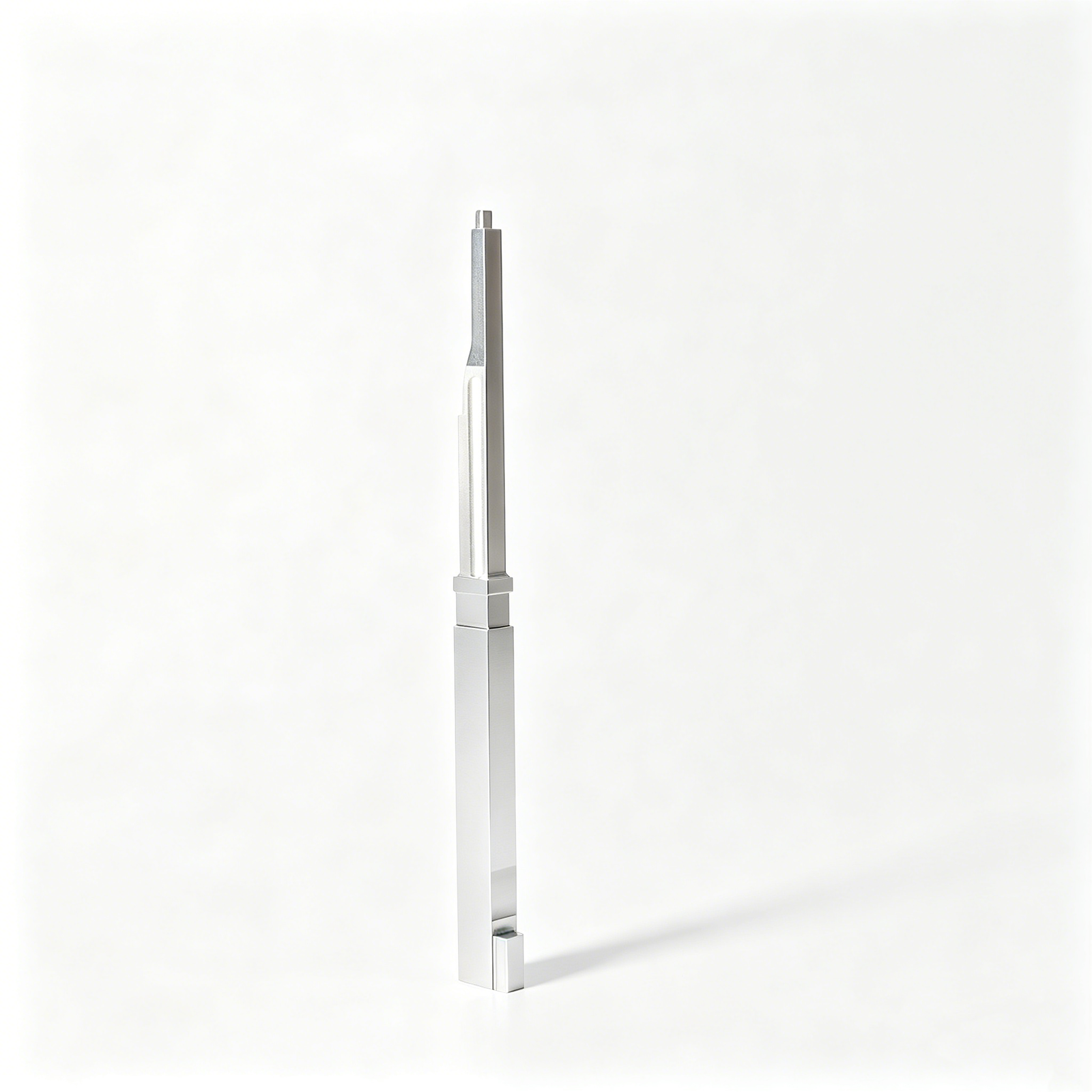


Related Configurable Component Families and Quotation







Precision Core Pins for Connector Molds: Engineering Advantages
Drawing-led planning for connector tooling where critical dimensions, process sequence, inspection, and revision visibility need to be defined before production.
Drawing Review First
Review 2D drawings and available models to identify datum relationships, feature priorities, and questions that affect quotation and manufacturability.
Critical Dimension Focus
Align critical-to-quality dimensions with appropriate machining, EDM, grinding, and inspection considerations before committing to a process route.
Process Route Planning
Plan machining access, electrode needs, wire paths, heat-treatment sequence, and grinding stock around the connector pin geometry.
Inspection Planning
Define inspection methods and reporting expectations against the drawing, with attention to critical features and order-specific quality requirements.
Revision Control
Keep drawing revisions, manufacturing questions, and approved changes visible so the production basis remains aligned throughout the project.
Traceable Communication
Coordinate material, quantity, delivery, and inspection details through documented project communication for clearer sourcing and quality decisions.
Precision Mold Components and CNC Process Routes
Drawing-driven manufacturing for connector tooling, mold components, die parts, and custom machined requirements requiring controlled process and inspection planning.

CNC Machining Services
Precision CNC machining services begin with drawing review, material requirements, critical dimensions, quantity, and inspection needs. Process planning may combine milling, turning, EDM, grinding, fitting, and measurement according to the part geometry and verified project scope.
Upload a Drawing
CNC Milling
Custom CNC milling services support prismatic parts, pockets, holes, contours, and mold-component features. Review focuses on datum definition, tool access, corner conditions, machining allowance, surface requirements, and whether downstream EDM or grinding is needed.
Upload a Drawing
CNC Turning
Precision CNC turning services are suited to rotational features such as pins, sleeves, bushings, shafts, and locating components. Drawings should identify critical diameters, concentricity, runout, threads, surface requirements, material condition, and inspection priorities.
Upload a Drawing
5-Axis Machining
5-axis CNC machining supports complex surfaces and multi-face features where setup reduction or angled tool access matters. A drawing review should confirm reachable geometry, datum strategy, fixture approach, tool clearance, tolerance relationships, and required finishing processes.
Upload a Drawing
Swiss & Micro Machining
Swiss machining and micro machining support small, detailed components where feature scale, material behavior, and handling affect the process route. Provide dimensions, tolerances, surface requirements, quantity, and any mating-part context for an informed manufacturability review.
Upload a Drawing
Wire & Sinker EDM
Wire EDM services and sinker EDM services address internal profiles, narrow slots, hardened features, sharp internal geometry, and forms that are difficult to mill directly. Electrode strategy, wire path, finish requirement, recast-layer considerations, and inspection points should be reviewed before production.
Upload a Drawing
Precision Grinding
Precision surface and profile grinding is used when flatness, parallelism, profile control, surface condition, or final size requires a controlled finishing operation. Grinding stock, heat-treatment sequence, datum references, and measurement method should be defined on the drawing.
Upload a Drawing
Mold Core Inserts and Mold Cavity Inserts
Precision mold core and cavity inserts are configured from the mold design, resin or material context, feature geometry, cooling requirements, surface condition, and tolerance plan. Manufacturing may require CNC machining, EDM, grinding, fitting, and documented inspection.
Upload a Drawing
Ejector & Ejection Components
Ejector pins, sleeves, and ejection components are produced to the mold’s moving-system requirements. Define diameters, fit relationships, stroke-related features, material and heat-treatment requirements, surface needs, and the mating components that govern functional clearance.
Upload a Drawing
Core Pins, Guide & Locating Components
Core pins, guide pins, and locating components require clear control of functional diameters, datum relationships, lead-ins, engagement lengths, and mating fits. The production route may include turning, grinding, EDM, and inspection based on the component design.
Upload a Drawing
Slides, Lifters, Gates & Mold Accessories
Mold slides, lifters, gates, and accessories are configured around movement, shutoff conditions, parting-line geometry, wear areas, and assembly interfaces. Drawings should identify critical fits, surface requirements, heat-treatment sequence, and any fitting or inspection expectations.
Upload a Drawing
Connector Mold Components
Precision connector mold components support fine-pitch and high-repeatability tooling requirements where feature relationships and mating interfaces matter. Review should cover cavity or core geometry, pin and insert locations, EDM needs, material condition, datum strategy, and inspection evidence.
Upload a Drawing
Stamping Die Components
Precision stamping die components are made from drawings for forming, cutting, guiding, and locating functions. Material, hardness, working edges, clearance relationships, surface condition, and fitting requirements should be established before selecting CNC, EDM, grinding, and inspection steps.
Upload a Drawing
Injection, MIM, CIM & Overmolding Tooling
Injection mold components and associated MIM, CIM, and overmolding tooling work are evaluated within verified production scope. Supply the component drawing, application context, material behavior, critical features, tool interfaces, surface requirements, and required inspection documentation for process review.
Upload a Drawing
Machining Materials
CNC machining materials are selected against function, machinability, wear, corrosion exposure, hardness condition, dimensional stability, and downstream treatment. State the specified grade, material condition, approved substitute rules, and any traceability requirements in the RFQ.
Upload a Drawing
Surface Finishes & Heat Treatment
Surface finishing and heat treatment must match the part’s function, geometry, dimensional priorities, and mating conditions. Specify finish type, hardness or treatment requirement, coating areas, masking needs, post-treatment grinding allowance, and acceptance criteria.
Upload a Drawing
Quality, Metrology & Documentation
Precision inspection, metrology, and quality documentation are planned around the drawing’s critical dimensions, datums, tolerances, and reporting requirements. Define measurement methods where necessary, sampling expectations, revision status, material records, and required inspection outputs.
Upload a Drawing
Prototyping & Low-Volume Production
Rapid prototyping and low-volume manufacturing support drawing-based evaluation, bridge quantities, tooling development, and controlled repeat orders. Share the current revision, quantity range, target date, material, critical dimensions, surface requirements, and inspection needs for a practical review.
Upload a DrawingPrecision Core Pins for Connector Molds: Material Options

Tool Steel
A practical choice for general connector tooling where balanced machinability, heat-treatment response, and wear resistance are needed. Final grade selection should consider pin geometry, resin abrasiveness, polishing requirements, and inspection-critical dimensions.

High-Speed Steel
Suited to slender or fine-feature core pins where wear resistance and dimensional stability after heat treatment require careful review. Grinding stock, straightness control, and the requested surface finish should be defined on the drawing.

Stainless Tool Steel
Considered for molding environments where corrosion resistance and polishability are important. The material and heat-treatment route should be matched to resin behavior, cooling exposure, surface expectations, and connector feature geometry.

Powder Metallurgy Steel
An option for demanding wear conditions when a suitable grade, heat-treatment plan, and finishing route are confirmed. Its selection should account for abrasive fillers, feature detail, EDM strategy, grinding allowance, and required documentation.

Carbide Material
Used selectively for high-wear or extremely small forming features when brittleness, support geometry, and assembly conditions are understood. SUUXIANG reviews tool access, EDM or grinding feasibility, mating-part fit, and inspection requirements before quotation.
Machining Routes for Precision Core Pins for Connector Molds


Wire EDM
Wire EDM supports narrow slots, fine profiles, and through-features where conventional tools cannot reach cleanly. The wire path, start-hole position, corner condition, and finish requirement should be defined against the connector mold drawing.

Sinker EDM
Sinker EDM forms deep, blind, or intricate geometry requiring a controlled electrode strategy. Electrode design, spark access, corner detail, and allowance for finishing are considered when molded features cannot be machined directly.


Fitting and Assembly
Fitting checks the practical relationship between the pin and its mating mold components. Clearance, alignment, insertion direction, and assembly-sensitive features are reviewed so drawing-based parts support the intended tooling interface.

Inspection Planning
Inspection is planned around the order’s critical dimensions, datums, surface requirements, and reporting needs. Measurement methods and documentation expectations should be agreed before production, helping maintain traceability across revisions and final delivery.
Precision Core Pins for Connector Molds: Features and Accessories

Locating Features
Dowel holes, locating flats, shoulders, and reference surfaces can support repeatable orientation and assembly of precision core pins for connector molds. Define mating-part relationships, datum references, and critical fits in the drawing package.

Pin Identification
Part numbers, cavity positions, revision marks, and other identification details can help maintenance teams control interchangeable components. Provide marking location, content, legibility requirements, and any surface restrictions for engineering review.

Guide Components
Guide and locating elements may be supplied alongside core pins when their functional relationship is clearly defined. Share assembly drawings, mating dimensions, load direction, and required movement so the process route can be assessed.

Ejection Details
Ejector interfaces, reliefs, retention features, and clearance relationships affect fitting and service access in connector tooling. Include the ejection arrangement and critical dimensions to support DFM, machining planning, and inspection preparation.

Assembly Interfaces
Threads, mounting faces, anti-rotation details, and insert interfaces can be machined to support the intended mold assembly. Material condition, torque or retention needs, datum strategy, and mating-component information should accompany the RFQ.
About SUUXIANG Precision Manufacturing
SUUXIANG is the international-facing brand of Dongguan SuuXiang Precision Mold Co., Ltd., established in 2010 and based in Chang’an Town, Dongguan, Guangdong, China. XiaoCheng Huang is the founder and legal representative. We help global engineering, sourcing, and quality teams turn drawings and specifications into inspected custom CNC parts, precision mold components, and connector-tooling work.
For precision core pins for connector molds, project planning brings together CNC milling and turning, multi-axis machining, EDM, precision grinding, fitting, and inspection as the drawing requires. Before quotation and production commitments, we review critical dimensions, datums, material and heat-treatment requirements, tool access, finishing needs, and inspection expectations.
Our difference is disciplined project communication. We treat core pins and related mold components as drawing-based, configurable work—not an assumed catalog item—and keep revision control, process decisions, and required quality documentation visible throughout the order. Share the application context and mating-part requirements so manufacturability can be assessed responsibly.

Precision Core Pins for Connector Molds: Critical Capability Review
DFM and Datum Strategy
Before quotation, SUUXIANG reviews the drawing’s critical dimensions, datum references, tolerance stack, mating geometry, and feasible tool access. This establishes how the pin will be located, machined, inspected, and referenced through production rather than treating every dimension as independent.
- Identify functional datums and critical-to-quality features
- Review slender-pin geometry, tolerances, and mating interfaces
- Clarify 2D drawing, 3D model, revision, and application context
- Flag manufacturability questions before production commitments
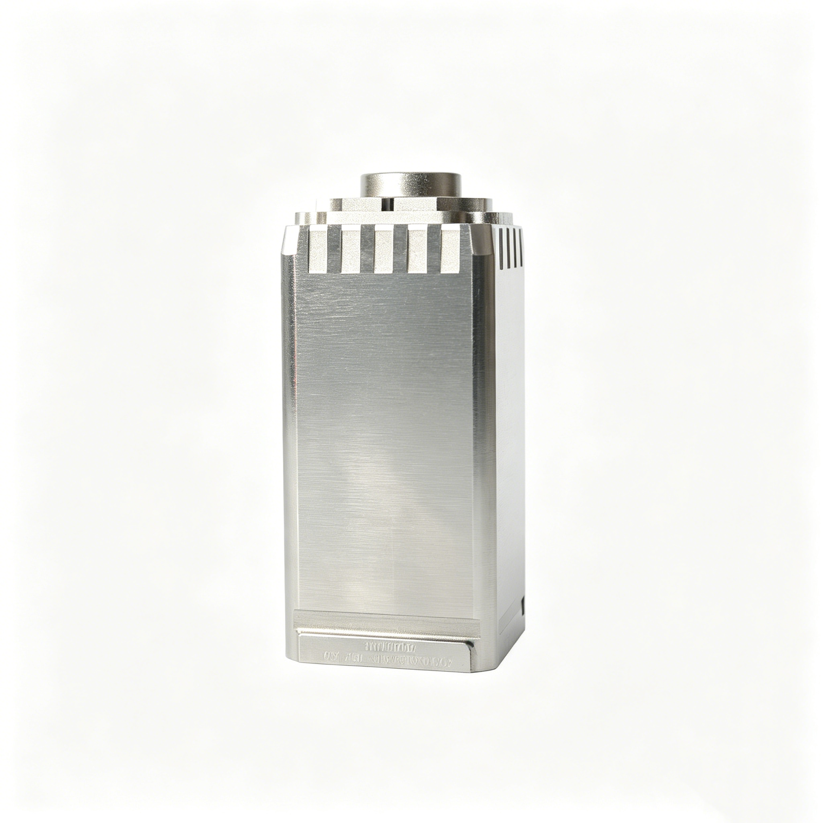
EDM Access Planning
Connector geometry can require features beyond practical cutting-tool access. SUUXIANG evaluates wire path, electrode direction, clearance, corner conditions, and finishing sequence so EDM is planned around the required geometry while preserving stable reference surfaces for later operations and inspection.
- Assess wire-EDM paths for narrow or enclosed profiles
- Define electrode approach for detailed formed features
- Check clearance, corner relief, and flushing considerations
- Coordinate EDM sequence with finishing and datum retention

Grinding Allowance Control
For precision core pins for connector molds, grinding is planned as a controlled finishing operation, not an afterthought. The review considers material condition, heat-treatment sequence, machining allowance, straightness needs, and surface requirements before stock is assigned for final grinding.
- Set grinding stock against material and heat-treatment sequence
- Preserve sufficient allowance after CNC and EDM work
- Review straightness, diameter, and surface priorities together
- Align final finishing with functional fit requirements

Inspection Plan Alignment
Inspection planning starts with the drawing and the features that affect mold fit and molded-part function. SUUXIANG aligns measurement methods, datum setup, reporting needs, sampling expectations, and revision traceability with the order before final inspection documentation is prepared.
- Define measurable critical features and inspection datums
- Match inspection records to agreed drawing revisions
- Confirm required reports and customer quality expectations
- Keep project communication visible through delivery coordination

What to Confirm When Selecting a Supplier for Connector-Mold Core Pins
A drawing-driven workflow built around DFM, critical dimensions, inspection planning, and visible revision coordination.
← Swipe left or right to view →
Precision Core Pins for Connector Molds: From Drawing to Shipment
A controlled, drawing-driven sequence that keeps critical dimensions, process decisions, inspection expectations and revision status visible throughout production.
Review RFQ Package
We review drawings, models, material, quantity, application context, delivery target and reporting needs; unclear critical requirements are identified before quotation.
Plan Process Route
The team confirms datums, critical dimensions, machining access, heat-treatment sequence, EDM strategy, grinding allowance and inspection methods for the approved revision.
Machine Critical Geometry
CNC milling, turning, multi-axis machining, wire EDM or sinker EDM are applied as the geometry requires, with process control aligned to drawing priorities.
Grind And Fit Components
Grinding and fitting address functional diameters, mating surfaces, straightness and assembly relationships where the drawing and planned process route require them.
Inspect Pack Coordinate
Final verification follows the order-specific inspection plan; parts are packed with applicable documentation and shipment coordination is confirmed against the current delivery arrangement.
How to Source Precision Core Pins for Connector Molds
A practical engagement path from drawing review through controlled production and inspection.
Submit Your Requirements
Upload 2D drawings, 3D models, material and heat-treatment requirements, quantities, critical dimensions, surface priorities, delivery target, and mating-component context affecting manufacturability.
Review DFM and Quote
Confirm datum strategy, tolerance stack, machining access, EDM or grinding needs, inspection method, revision status, and commercial details before SUUXIANG issues a controlled quotation.
Approve Samples When Needed
For projects requiring samples, review agreed dimensions, finish expectations, and inspection evidence against the approved drawing before releasing the production route.
Release Controlled Production
SUUXIANG coordinates machining, EDM, grinding, fitting, inspection, and delivery updates against the confirmed revision and inspection plan for precision core pins for connector molds.
Quality Documentation for Precision Core Pins for Connector Molds
Customer Feedback on Precision Core Pins for Connector Molds
Reserved for an approved customer case describing the drawing revision, critical dimensions, inspection evidence, quantity, and verified connector-mold outcome. No customer testimonial or performance figure is published before written approval.
Reserved for an approved customer case covering DFM feedback, process route, datum requirements, and documented results for precision core pins for connector molds. Project-specific figures will be published only after verification.
Reserved for an approved customer case addressing fit, repeatability, inspection reporting, and delivery coordination for a drawing-based connector tooling program. SUUXIANG will publish only attributable, project-verified customer feedback.
Precision Core Pins for Connector Molds FAQ
Practical answers for drawing-based RFQs, quality planning, and controlled production discussions.
What information should I include in an RFQ for precision core pins for connector molds?
Can SUUXIANG quote low-volume precision core pins for connector molds?
How do you review drawings for precision core pins for connector molds before production?
Can I request samples or a first-article inspection before a larger order?
Which materials and heat treatments are suitable for connector mold core pins?
What inspection reports can be requested with a connector mold pin order?
How long does it take to manufacture precision core pins for connector molds?
How are shipping, intellectual property, and drawing revisions controlled?
Complete Buyer’s Guide to precision core pins for connector molds
Use this decision framework to specify geometry, materials, tolerances, inspection, and supplier controls for connector tooling—while avoiding sourcing mistakes that can cause fitting problems, inconsistent cavities, and avoidable qualification delays.
1. What Are Precision Core Pins for Connector Molds?
A precision core pin is a mold component that projects into the cavity to form a connector’s internal holes, cavities, terminal passages, and mating interfaces. Its geometry transfers directly to the molded feature, while its mounting fit locates that feature relative to the tool datums.
For fine-feature electronics tooling, small changes in diameter, straightness, and surface condition can affect passage clearance, part release, flash risk, and interface alignment. These relationships must be evaluated against the specific drawing and molding application rather than a generic size benchmark.
Two drawing-review questions define the purchase: what exact feature must the pin form, and what production conditions must it withstand? Specify the critical dimensions and datums, cavity-to-cavity matching requirement, resin and molding conditions, expected cycles, mating-part function, surface requirement, and inspection evidence before selecting the manufacturing route.
2. How Connector-Mold Core Pins Evolved
Connector-mold core-pin requirements have moved from individual replaceable forming elements toward controlled, repeatable sets as cavities become smaller and contact counts rise. Drawing-defined diameters, datums, lengths, reliefs, and identification help replacement pins fit without reworking adjacent components.
Multi-cavity tools require the buyer to consider consistency across the set, not only the nominal size of an individual pin. Pin diameter, straightness, surface condition, and mounting relationships can all affect molded geometry and replacement fit.
100% inspection is not inherently necessary for every dimension, but critical features need an agreed method, sampling plan, and record. Modern maintainability depends on revision-controlled drawings, traceable identification, and inspection evidence that lets a toolroom compare a replacement against the released requirement.
3. Types of Precision Core Pins for Connector Molds
Six recurring configurations cover most connector tooling: straight, stepped, tapered, headed, ejector-related, and special-profile pins or mandrels. Select the geometry from the molded feature first, then confirm access, support, release, and inspection requirements during DFM.
| Configuration | Feature Formed | Quote Details |
|---|---|---|
| Straight | Uniform bore or passage | Diameter, length, datum |
| Stepped | Shoulder or counterbore | All diameters, step locations |
| Tapered | Tapered bore or release feature | Taper angle, end diameters |
| Headed | Retained forming feature | Head dimensions, seating face |
| Ejector-related | Moving formed feature | Travel, fit, clearance |
| Special-profile | Slot or irregular passage | 3D model, profile datums |
Start With The Formed Feature
Straight pins form uniform holes or passages; stepped pins form shoulders, counterbores, or diameter transitions. Tapered pins help create tapered bores or release-sensitive features; state every functional diameter and axial location.
Headed pins locate against a plate or retainer, while ejector-related pins combine feature formation with mold movement. Identify the bearing diameter, head geometry, travel relationship, and any non-forming clearance.
Define Nonstandard Profiles
Special-profile pins and mandrels form slots, keyways, ribs, irregular internal contours, or complex connector passages. Supply a section view or 3D model when the profile cannot be fully controlled by standard orthographic views.
Two datum references should establish where the profile is measured, and the drawing should distinguish molded surfaces from relief. Include corner radii, draft, blend transitions, orientation, and permissible EDM witness locations.
4. Materials for Precision Core Pins for Connector Molds
Three material families cover most drawing-based decisions for precision core pins for connector molds. Select against resin abrasiveness, expected cycles, pin slenderness, cooling conditions, and the required molded surface.
| Material Family | Wear And Toughness | Corrosion And Polish | Best-Fit Decision |
|---|---|---|---|
| Pre-hardened or hardened tool steel | Balanced; choose grade for load and geometry | Lower corrosion resistance; polishability varies | General connector resins and supported pin geometry |
| Stainless tool steel | Moderate-to-high wear with grade-dependent toughness | Higher corrosion resistance; often polishable | Corrosive resins, humid storage, or cosmetic surfaces |
| Carbide | Very high wear resistance; limited impact tolerance | Corrosion behavior and polish route require review | Abrasive resin, high volume, short rigid features |
| Coating over base material | Adds surface protection; does not replace substrate toughness | Depends on coating and preparation | Wear or release issue confirmed by application review |
Specify Heat Treatment And Finish
Heat treatment must state steel grade, target hardness range, distortion-control expectations, and the sequence relative to finish grinding. A hard specification without a grinding allowance can compromise size or straightness.
Surface finish should identify the functional area, roughness or polish requirement, and whether EDM texture removal is required. Coatings are conditional: assess adhesion, thickness effect, sliding contact, and the resin before specifying one.
5. Custom Features and Identification Options
A connector core pin is normally made to drawing, not selected from a catalog. Define the geometry that controls molded fit, tool assembly, release, and maintenance before requesting quotation.
| Method | Traceability Value | Surface Constraint |
|---|---|---|
| Laser marking | Individual part ID | Keep off functional surfaces |
| Dot peen marking | Durable visible ID | Avoid thin or polished areas |
| Bag and label | Lot-level identification | No part-surface impact |
Define Forming Geometry

Diameter, step locations, taper angle, nose radius, and relief diameter should carry explicit dimensions and tolerances. Do not assume a standard transition radius or draft when the pin forms a mating connector feature.
- Identify functional diameters and datum origin.
- Dimension each step and relief length.
- Call out allowable edge breaks.
Specify Mounting And Finish
Head geometry, flats, threads, wrench features, and anti-rotation details require both dimensions and datum references. State whether surface finish is cosmetic, sliding, sealing, or molding-functional; coating type and coverage must be called out directly.
- Define thread standard and engagement.
- Mark no-coating or masking zones.
- Separate polish requirements from Ra requirements.
Choose Identification Method
Permanent identification should be located away from molding, sliding, sealing, and fit surfaces. Specify the required ID, marking position, character size, and whether the mark must survive cleaning, handling, or heat treatment.
- Link pin ID to drawing revision.
- Use inspection records for lot traceability.
- Keep cosmetic surfaces mark-free.
6. Critical Quality Elements in Core-Pin Construction
Nominal diameter alone does not define a reliable core pin. For precision core pins for connector molds, the drawing should assign measurable acceptance criteria to every feature that controls fit, molding behavior, or replacement.
Datums And Geometric Control
A datum-based tolerance scheme separates functional diameter from seating, tip, and shoulder relationships. Straightness, roundness, and concentricity or runout should be measured against stated datums; otherwise a pin can size correctly yet misalign cavities, alter wall consistency, or create flash.
Finish And Edge Condition
A specified surface-finish limit should cover the forming land and any release-critical transition. Surface texture, damaged edges, and residual burrs can impede release, score mating features, trap material, and shorten wear life; define the inspection method and permissible edge break on the drawing.
Heat Treatment And Verification
A hardness requirement needs its test location, scale, and acceptable range, plus a distortion-control plan when heat treatment follows machining. Reinspect critical dimensions, runout, and surface condition after heat treatment and grinding so replacement pins remain interchangeable with the released mold assembly.
7. Choosing a Precision Core-Pin Manufacturer
Two supplier conversations reveal more than a capability list: the drawing review and evidence package. For precision core pins for connector molds, select a manufacturer that records decisions before machining.
| Stage | Evidence To Request | Decision Use |
|---|---|---|
| Prototype | Marked drawing and inspection plan | Validate feasibility |
| Low Volume | Traveler and material records | Check process control |
| Repeat Sets | Revision history and packing standard | Support replacement continuity |
Drawing Review Evidence
One reviewed mark-up should identify critical dimensions, datums, tool access, and the EDM or grinding route. Ask for stated deviations and revision-response ownership.
Two scenarios—prototype and repeat set—should receive separately confirmed feasibility. A quotation alone does not demonstrate DFM.
Traceability And Control
One traveler should connect the drawing revision, material requirement, process route, and inspection plan. Request sample records, not generic claims of quality control.
Two identifiers—part number and revision—should remain visible through machining, inspection, and packaging. Heat-treatment evidence must match the order requirement.
Release And Continuity
One first-article agreement should define measured features, report format, acceptance criteria, and approval status. Confirm who communicates nonconformities and delivery changes.
Two packaging controls—individual protection and legible labeling—reduce damage and mix-ups. For replacements, require retained drawings, revision history, and repeatability review.
8. Common Buyer Mistakes and Prevention
Two release gaps—an unclear drawing and an unverified inspection basis—can turn a conforming pin into an assembly problem. For precision core pins for connector molds, engineering and procurement should close these gaps before release.
Drawings, Datums, And Stacks
One incomplete print can omit functional datums, mating references, or a stack analysis. Prevent this with a controlled 2D/3D package and CTQ review; ask, ‘Which datums govern fit, and what cumulative variation is allowed?’
Material And Surface Context
One steel callout without resin, additives, temperature, and cycle context can misdirect material and finish decisions. Record molding conditions and required texture or polish; ask, ‘What wear, corrosion, release, and cosmetic risks must this pin manage?’
Spare-Pin Planning
One production tool without an approved spare-pin plan can prolong downtime after damage or wear. Define interchangeable identifiers, revision status, quantity, and inspection records; ask, ‘Which pins require qualified spares before the mold runs?’
Acceptance Beyond Nominal Size
One nominal-dimension-only approval overlooks runout, straightness, surface condition, and measurement method. Approve a CTQ-based inspection plan; ask, ‘Which geometric and surface results must accompany acceptance?’
9. From DFM Review to Production Release
Seven controlled gates prevent a quoted pin from becoming an unverified mold change. For precision core pins for connector molds, each gate should create a dated, revision-controlled record.
Define The Technical Package
Gate 1: Engineering supplies the 2D drawing, 3D model, resin, cavity count, mating details, and operating context.
Gate 2: The supplier returns DFM comments covering datums, tool access, EDM strategy, heat-treatment sequence, and grinding stock.
Freeze CTQs And Approval
Gate 3: Quality identifies CTQs, inspection methods, sampling expectations, surface criteria, and required report content.
Gate 4: Procurement approves the quotation, agreed revision, quantity, delivery requirement, and first-article scope before release.
Validate And Control Repeats
Gate 5: Quality reviews first-article results against the approved drawing and inspection plan before mold installation.
Gate 6: Engineering validates fit, venting, release, and molded-part function; deviations require documented disposition.
Gate 7: Procurement issues repeat orders only against the released revision, while the supplier maintains traceable change and delivery records.
10. Precision Core-Pin Pricing and Cost Drivers
1 completed drawing review is required before SUUXIANG can issue an accurate quotation for precision core pins for connector molds. The review should confirm datums, critical dimensions, material, heat treatment, finish, quantity, inspection evidence, and requested delivery date.
3 cost lenses matter after unit price: replacement risk, mold downtime exposure, and qualification effort. Compare documented conformity and revision traceability alongside the quoted part cost, especially for repeat sets or high-cavitation tools.
| Order condition | Primary cost drivers | Quotation evidence needed |
|---|---|---|
| 1–5 replacement pins | Programming, setup, complex geometry, tight tolerance | Current drawing, mating context, target date |
| Small repeat set | Material, EDM or grinding route, surface finish | Quantity, hardness requirement, critical datums |
| Larger repeat quantity | Pin-to-pin consistency, inspection sampling, packaging | Set count, interchangeability requirement, report format |
| Expedited requirement | Capacity confirmation, routing constraints, documentation priority | Required date and acceptable process alternatives |
Request a Quote for Precision Core Pins for Connector Molds
Send your drawing, 3D model, material, quantity, critical dimensions, inspection needs, and target delivery date for a scoped RFQ review.