
Prototype Injection Molds, Reviewed Before Tooling Begins
Submit your drawing to align prototype injection molds with critical dimensions, datum strategy, machining access, and inspection requirements before quotation.
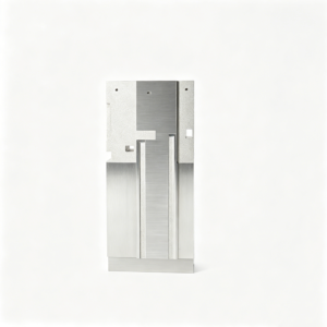
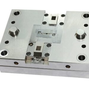
Representative Components for Prototype Injection Mold Development





Related Components and RFQ Support





Advantages of Prototype Injection Molds with Disciplined DFM
Build a clearer route from drawing review through machining, EDM, grinding and inspection before prototype tooling commitments are made.
Drawing-First DFM Review
Review critical dimensions, datum strategy, tool access, parting requirements and likely manufacturing risks before quotation or prototype tooling production begins.
Integrated Process Planning
Coordinate CNC machining, EDM, precision grinding and fitting around the geometry, material condition and surface requirements defined for each component.
Critical-Dimension Focus
Identify functional interfaces and tolerance-sensitive features early, so machining allowances, electrode strategy and inspection methods can be planned appropriately.
Inspection Plan Alignment
Match measurement priorities and reporting expectations to the order, helping teams verify prototype mold components against agreed drawing requirements.
Visible Revision Control
Keep drawing revisions, manufacturing discussions and delivery information visible, reducing ambiguity when design updates affect prototype injection molds.
Prototype Tooling and Precision Component Families
Drawing-driven process routes for prototype tooling, configurable mold components, connector tooling, die parts, and custom machined work requiring defined inspection and revision control.

CNC Machining Services
Precision CNC machining services begin with drawing review, material requirements, critical dimensions, and inspection expectations. SUUXIANG plans suitable milling, turning, EDM, grinding, and fitting steps for custom parts within the verified requirements of each project.
Upload a Drawing
CNC Milling
Custom CNC milling services support prismatic parts, plates, inserts, pockets, contours, and machined features requiring deliberate tool access and datum control. The review should define tolerances, surface requirements, machining allowance, material condition, and inspection points before production.
Upload a Drawing
CNC Turning
Precision CNC turning services support shafts, pins, sleeves, bushings, stepped diameters, threads, and other rotational features. Drawings should clarify functional diameters, runout or concentricity requirements, datum references, material condition, and any later grinding or heat-treatment sequence.
Upload a Drawing
5-Axis Machining
5-axis CNC machining can reduce setups for complex contours, angled features, deep pockets, and multi-face parts. Feasibility depends on tool reach, fixture strategy, corner geometry, material, tolerance requirements, and the inspection method selected during drawing review.
Upload a Drawing
Swiss & Micro Machining
Swiss machining and micro machining support small, slender, and detail-intensive components such as precision pins, miniature shafts, sleeves, and connector-related parts. Review critical diameters, length-to-diameter relationships, burr control, surface needs, material, and measurement access before committing to a route.
Upload a Drawing
Wire & Sinker EDM
Wire EDM and sinker EDM services address hardened features, narrow slots, internal corners, intricate profiles, and forms beyond conventional tool access. Process planning should consider wire path, electrode strategy, flushing, recast-layer requirements, stock condition, and finishing or inspection needs.
Upload a Drawing
Precision Grinding
Precision surface and profile grinding is used where flatness, parallelism, profile control, fine surface requirements, or final sizing demand a controlled finishing step. Drawings should identify datums, grinding stock, heat-treatment condition, critical surfaces, and applicable inspection criteria.
Upload a Drawing
Mold Core & Cavity Inserts
Precision mold core and cavity inserts are configurable components produced from customer drawings and mold design requirements. Manufacturing review addresses parting geometry, cooling or feature access, material and heat treatment, EDM strategy, matching surfaces, critical dimensions, and fitting expectations.
Upload a Drawing
Ejector & Ejection Components
Ejector pins, sleeves, and ejection components require attention to fit, straightness, working diameter, head geometry, surface condition, and mating-hole requirements. Provide the ejection layout, material specification, heat-treatment needs, and any coating or inspection requirements with the RFQ.
Upload a Drawing
Core Pins, Guide & Locating Components
Core pins, guide pins, and locating components are reviewed as functional interfaces, not generic catalog items. Define mating relationships, datum strategy, fit class, hardness or material condition, concentric features, surface requirements, and the inspection evidence needed for assembly.
Upload a Drawing
Slides, Lifters, Gates & Mold Accessories
Mold slides, lifters, gates, and accessories are made to drawing-defined geometry and assembly interfaces. A practical review covers travel or motion constraints, wear surfaces, clearances, material and heat treatment, lubrication considerations, EDM access, and fitting responsibility.
Upload a Drawing
Connector Mold Components
Precision connector mold components may include fine-pitch cavities, inserts, pins, locating features, and other tooling elements with demanding alignment requirements. Submit mating-component context, critical pitch or profile dimensions, material condition, surface requirements, and inspection priorities for review.
Upload a Drawing
Stamping Die Components
Precision stamping die components include punches, dies, inserts, guides, and wear parts produced to the required functional geometry. Process planning considers tool steel selection, heat-treatment sequence, wire or sinker EDM needs, grinding stock, edge condition, and mating clearances.
Upload a Drawing
Injection, MIM, CIM & Overmolding Tooling
Injection, MIM, CIM, and overmolding tooling work is evaluated against the specific component or tool requirement. Drawings and application context help identify suitable machining, EDM, grinding, fitting, material, thermal treatment, and inspection requirements within verified production scope.
Upload a Drawing
Machining Materials
CNC machining materials are selected from the drawing specification and the part’s functional conditions, including strength, wear, corrosion, electrical, thermal, and machining considerations. Confirm material grade, supply condition, traceability needs, and any heat-treatment or finishing sequence before production.
Upload a Drawing
Surface Finishes & Heat Treatment
Surface finishing and heat treatment must be tied to function, material, and dimensional risk. Identify required finish, roughness, coating, hardness, treatment sequence, masking needs, and post-treatment inspection dimensions so machining allowances and final checks can be planned correctly.
Upload a Drawing
Quality, Metrology & Documentation
Precision inspection, metrology, and quality documentation are planned around drawing-defined critical characteristics and agreed reporting requirements. Specify key dimensions, datums, sampling expectations, report format, material records, revision status, and any customer-defined measurement methods before production begins.
Upload a Drawing
Prototyping & Low-Volume Production
Rapid prototyping and low-volume manufacturing support drawing-based evaluation parts, prototype tooling components, engineering changes, and controlled small-batch requirements. A complete RFQ should include models or drawings, quantity, material, quality priorities, revision level, delivery target, and application context.
Upload a DrawingMaterial Routes for Prototype Injection Molds


Aluminum Tooling Alloys
Aluminum routes can support faster machining for selected prototype injection molds, especially when early design validation is the priority. Geometry, cooling layout, resin selection, wear expectations, and surface requirements require drawing-led review.

H13 Tool Steel
H13 may be considered for components exposed to elevated thermal cycling or demanding service conditions. The machining, EDM, heat-treatment, grinding allowance, hardness requirement, and inspection plan should be defined before commitment.

Stainless Mold Steel
Stainless mold steel can be assessed where corrosion resistance, surface condition, or specific resin and operating environments affect the tooling decision. Material grade, heat treatment, finish, and critical-dimension verification remain project-specific.

Copper Alloy Inserts
Copper-alloy inserts may be evaluated for localized thermal-management needs in tooling components. Their application depends on insert geometry, joining method, surrounding steel support, machining access, wear exposure, and documented design requirements.
Prototype Injection Molds: Machining and Finishing Processes

CNC Milling
CNC milling forms plates, inserts, pockets, channels, and external profiles from the drawing model. Tool selection and access are reviewed before machining to protect critical dimensions, leave appropriate stock, and prepare surfaces for EDM or grinding.

CNC Turning
CNC turning produces rotational features such as core pins, guide elements, sleeves, and locating components. Controlled datum setup supports concentricity and repeatable mating geometry, while secondary milling, EDM, or grinding can address non-round details.


Wire EDM
Wire EDM cuts precise profiles, narrow slots, corners, and through-features where conventional tool access is restricted. Wire path, start-hole placement, and finish-pass requirements are planned against the drawing so the resulting geometry can be inspected reliably.

Sinker EDM
Sinker EDM creates deep cavities, ribs, sharp internal features, and difficult-to-machine details using purpose-planned electrodes. Electrode strategy, spark allowance, and surface expectations are reviewed alongside subsequent fitting or polishing requirements before work begins.

Precision Grinding
Precision grinding brings critical faces, diameters, and fit surfaces toward their specified condition after machining or heat treatment. Grinding stock, datum references, and inspection method should be defined early to manage size, flatness, parallelism, and surface-finish priorities.
Prototype Injection Molds: Supporting Components

Guide Components
Guide pins, bushings and locating elements help establish repeatable mold alignment. Specify datum relationships, fit requirements, material and heat-treatment needs, and any mating-component constraints for a manufacturability review.

Ejector Parts
Ejector pins, sleeves, return elements and related ejection parts are made to drawing-defined dimensions. Review working lengths, bearing surfaces, clearance conditions, hardness requirements and surface expectations alongside the mold design.

Gate Inserts
Gate inserts and runner-related components can be planned around part geometry, resin flow requirements and tool access. Provide gate location, interface dimensions, finish needs and revision-controlled drawings for evaluation.

Tooling Fasteners
Fasteners, dowels and retention components support assembly of prototype injection molds where specified. Define thread standards, engagement lengths, locating strategy, material requirements and any installation or service-access constraints.

Identification Markings
Part numbers, cavity identifiers, date marks and controlled markings can improve traceability during sampling and inspection. Supply marking content, location, character requirements and any depth, finish or visibility limitations.

Custom Subassemblies
Drawing-led subassemblies combine compatible mold accessories for fitting and inspection planning. Clarify interfaces, assembly sequence, critical dimensions, acceptance criteria and documentation needs before committing to the process route.
About SUUXIANG Precision Manufacturing
SUUXIANG is the international-facing brand of Dongguan SuuXiang Precision Mold Co., Ltd., established in 2010 in Chang’an Town, Dongguan, Guangdong, China. We help global engineering, sourcing, and quality teams turn drawings and specifications into inspected custom parts, precision mold components, connector tooling, and prototype injection molds.
Our work begins with a disciplined drawing review: critical dimensions, datums, material and heat-treatment requirements, machining access, EDM or grinding needs, and inspection expectations. Process planning can combine CNC milling and turning, multi-axis machining, wire EDM, sinker EDM, precision grinding, fitting, and inspection according to verified project requirements.
What distinguishes SUUXIANG is controlled engineering communication from RFQ through delivery. We keep revision information, manufacturing decisions, and inspection planning visible, so buyers can evaluate risks before production commitments. Submit a 2D drawing, available 3D model, quantity, delivery target, and quality requirements for a scoped review.

Prototype Injection Molds: Core Tooling Capabilities
DFM and Datum Review
Prototype injection molds begin with a drawing-led review of functional geometry, critical dimensions, datum relationships, parting-line implications, and machining access. This early discussion identifies questions that should be resolved before a process route, inspection plan, or production commitment is defined.
- Review 2D drawings and available 3D models together
- Identify critical-to-quality dimensions and datum strategy
- Flag tool-access, wall-transition, and feature-risk questions
- Align material, quantity, application, and delivery requirements

CNC and EDM Strategy
Tooling components may require a planned combination of CNC machining, wire EDM, sinker EDM, and electrode work. SUUXIANG evaluates feature geometry, corner conditions, access paths, and required finishing operations so the selected route supports the drawing rather than forcing an unsuitable process.
- Match machining routes to geometry and access constraints
- Plan wire paths for internal profiles and narrow features
- Assess electrode needs for deep or complex cavity details
- Keep machining sequence visible as requirements evolve

Grinding and Fitting Control
Precision mold components often depend on controlled stock removal after machining or heat-treatment steps. Grinding allowance, mating relationships, and fitting requirements should be clarified from the drawing and application context, particularly where alignment, sliding action, or shutoff performance affects prototype injection molds.
- Define grinding stock and finishing sequence
- Review mating surfaces, guides, and locating relationships
- Consider heat-treatment timing before final dimensions
- Clarify fitting expectations for assembled tooling components

Inspection and Revision Traceability
Inspection planning should reflect the order’s critical features, specified reporting needs, and agreed datum scheme. SUUXIANG maintains visible revision and delivery coordination throughout the project, helping teams compare manufactured parts against the current drawing and verified inspection requirements.
- Align inspection methods with critical dimensions
- Confirm requested reports before production begins
- Control drawing revisions and order-specific requirements
- Provide documentation matched to the verified plan

Why Choose SUUXIANG for Prototype Injection Molds
Compare a drawing-based tooling-component workflow with less defined quotation and production coordination.
← Swipe left or right to view →
Prototype Injection Molds: Production Process
A drawing-led workflow that keeps DFM decisions, critical dimensions, process routing, inspection requirements, and delivery coordination visible before production proceeds.
RFQ and Drawing Review
Share 2D drawings, 3D models, material requirements, quantities, target dates, and inspection needs so SUUXIANG can define the manufacturing discussion.
DFM and Process Planning
Review datums, critical dimensions, tool access, machining allowance, heat-treatment sequence, and electrode or wire paths before quotation and production commitments.
CNC Machining Begins
Machine prototype injection mold components through the applicable CNC milling, turning, multi-axis, Swiss, or micro-machining route defined for the drawing.
EDM Grinding and Fitting
Apply wire EDM, sinker EDM, precision grinding, and fitting where geometry, surface requirements, hard material conditions, or functional interfaces require them.
Inspection and Delivery Coordination
Inspect agreed critical features against the verified plan, maintain revision traceability, then coordinate packing, documentation, and shipment information for the order.
How to Source Prototype Injection Molds
Move from drawing review to controlled production with defined technical inputs, approval points, and inspection expectations.
Submit Your Drawing Package
Provide 2D drawings, 3D models where available, material preferences, expected quantities, delivery targets, and inspection requirements so the project scope begins with usable engineering evidence.
Align DFM and Quote Scope
Review critical dimensions, datum strategy, machining access, EDM or grinding needs, and quality expectations with SUUXIANG before confirming a process route, inspection plan, and quotation.
Approve Tooling Details
Confirm revisions, tooling details, and sample or first-article acceptance criteria before releasing work; keep approved drawings and revision status visible through project coordination.
Release Controlled Production
Proceed with the agreed machining, EDM, grinding, fitting, and inspection sequence after approval, with documentation matched to the verified inspection plan and order requirements.
Prototype Injection Mold Customer Evidence: Pending Approval
Verified Prototype Injection Molds Customer Cases
Approved customer case pending: confirm the drawing revision, quantity, critical dimensions, inspection evidence, and measurable outcome before publication. This slot is reserved for a permissioned prototype tooling project testimonial.
Approved customer case pending: document the DFM issue reviewed, the machining or EDM process route, and one verified result before publication. Include only customer-approved project context and outcome data.
Approved customer case pending: capture the customer’s feedback on communication, revision control, delivery coordination, or inspection documentation. Publish a rating and named attribution only after written permission is confirmed.
The Complete Buyer’s Guide to Prototype Injection Molds
Practical answers for engineering and sourcing teams preparing a drawing-led tooling inquiry.
What files should I send for prototype injection molds?
Can SUUXIANG quote prototype injection molds from a drawing?
What is the minimum order quantity for prototype injection molds?
How is lead time evaluated for a prototype tooling project?
Can prototype injection molds support sample and design validation work?
What material information is needed before quoting tooling components?
What inspection reports can I request with my order?
How are payment, shipping, and IP requirements handled?
The Complete Buyer’s Guide to prototype injection molds
Use this practical framework to match prototype tooling to validation goals, assess supplier engineering and quality controls, compare material and tooling choices, and avoid costly design, specification, and handoff mistakes before production.
1. What Are Prototype Injection Molds?
Three distinct items are involved: the prototype injection mold is the short-run tool, injection molding is the process that fills its cavity, and the molded prototype is the resulting part. The tool is built from the released drawing and model to produce parts for fit, function, material behavior, and assembly checks.
One prototype route sits between additive samples and production tooling. Additive parts can quickly test form, while a prototype mold is appropriate when the team must evaluate molded geometry, the intended resin, gate-related effects, mating features, or repeated assembly using actual molded parts.
Two decisions should precede an RFQ: what learning the parts must provide and what dimensions are critical to that learning. Supply the 2D drawing, 3D model, resin and quantity, then identify datums, cosmetic areas, mating components, inspection needs, and the target decision date; tooling design and process feasibility should be reviewed before cutting the tool.
2. How Prototype Tooling Evolved
P20 and hardened tool steels became standard choices where a mold must resist long production runs, but hard machining, heat treatment, EDM, fitting, and validation make change costly. That economics encouraged teams to freeze geometry before committing to production tooling.
CNC-machined aluminum, pre-hardened steel, and other softer-tool approaches shifted the decision point earlier by making limited-run molded parts practical for fit, assembly, and material-related learning. The trade-off remains tool life and robustness, particularly with abrasive resins; prototype tools are a development route, not automatically a production substitute. https://www.teameliteonline.com/how-to-utilize-prototype-injection-molding-in-the-development-of-custom-plastic-products
MUD, or master unit die, systems use a reusable frame with removable cavity and core inserts, so a revision can target the affected insert rather than the entire tool. Digital DFM added earlier checks for draft, wall transitions, gates, parting lines, undercuts, datum requirements, and tool access; teams can therefore test molding-related risks before authorizing hardened production tooling. https://www.fictiv.com/articles/prototype-injection-molding-the-ultimate-guide
3. Types of Prototype Injection Molds
Tool architecture should follow the program stage, not a default mold material. Compare revision risk, resin behavior, required samples, and the evidence needed before committing to a longer-life tool.
| Architecture | Best Program Stage | Iteration | Durability | Complexity Fit |
|---|---|---|---|---|
| Aluminum tool | Early validation | High | Lower | Moderate features |
| Pre-hardened steel | Late prototype | Moderate | Higher | Demanding features |
| Insert-based or MUD | Changing geometry | High | Frame retained | Localized inserts |
| Single-cavity | Process learning | High | Lower output | Debuggable parts |
| Multi-cavity | Repeatability samples | Lower | Higher output | Balanced filling |
| Bridge tooling | Pre-production | Moderate | Intermediate | Production-like intent |
Tool Material And Inserts
Aluminum tools suit early functional trials when machining speed and easy rework outweigh extended service life.
Pre-hardened steel favors more abrasive resins, tighter wear control, or later-stage repeatability. Insert-based or MUD-style frames localize revisions to replaceable cavity and core inserts.
Cavity Count And Bridge Path
Single-cavity tools simplify debugging of fill, cooling, shrinkage, and dimensional variation. They are usually the clearer choice while geometry remains unsettled.
Multi-cavity tools test repeatability and higher sample demand, but multiply balancing and correction work. Bridge tooling supports limited pre-production while production architecture is still being finalized.
4. Materials for Prototype Injection Molds
Prototype injection molds have two distinct material decisions: the tool material and the resin being validated. Match both to the test objective, expected shots, and any production-relevant processing risk.
| Testing purpose | Tool approach | Resin choice | Key evidence |
|---|---|---|---|
| Fit and assembly | Aluminum or insert tool | Commodity resin | Geometry and assembly clearance |
| Functional validation | Steel inserts where needed | Specified engineering resin | Shrinkage and performance |
| Wear-risk assessment | Steel contact surfaces | Filled or abrasive grade | Tool wear and surface stability |
Tool Material Strategy
Aluminum shortens machining time and suits early fit, assembly, and limited-run trials. Pre-hardened or hardened tool steel better supports repeated cycling, tight shutoffs, and steel moving components.
Insert-based tools combine a reusable frame with replaceable cavity or core inserts. This approach confines likely design changes and wear to the features under evaluation.
Resin Selection Changes Evidence
Commodity resins can establish fill, appearance, and basic assembly behavior economically. Engineering thermoplastics and elastomers are more relevant when heat, stiffness, sealing, or snap performance drives the decision.
Filled grades alter flow, shrinkage, and surface replication; glass-filled resins can accelerate wear in softer tooling. Confirm the specified grade, moisture conditioning, and processing window before treating samples as production-representative.
Align Test And Tool
100% production-equivalent resin is most valuable when approval depends on functional behavior rather than geometry alone. Record resin supplier, grade, colorant, regrind policy, molding conditions, and measured shrinkage with the inspection results.
5. Prototype Injection Molds: Part Features
Prototype injection molds expose feature-level decisions that CAD alone can conceal. A drawing-led DFM review should lock datums, critical interfaces, resin assumptions, and the intended revision boundary before insert machining begins.
Wall Sections And Release
1.0× nominal walls cool more uniformly than abrupt thick-to-thin transitions; cores, ribs, and bosses should avoid local mass that sinks or warps. Draft must be assigned by surface, texture, and draw direction so cosmetic faces release without drag marks.
Side Actions And Threading
2.0 directions of mold opening should be checked for undercuts, threads, and shutoffs. Slides, lifters, unscrewing features, or hand loads add tool complexity, witness-line risk, and revision cost; connector teams should identify mating-face priorities first.
Flow, Ejection, And Tolerance
3.0 tool features require a gate, runner, vent, and ejection concept matched to the part. Gate location influences weld lines and cosmetics; vents prevent trapped gas, while ejector placement protects thin sections and functional faces.
0.00 tolerance callouts are not manufacturing instructions without datums, measurement method, and material condition. SUUXIANG should review critical dimensions, shrink-sensitive interfaces, steel-safe changes, grinding or EDM access, and inspection evidence against the controlled drawing revision.
6. Finishes, Marking, and Secondary Operations
Before tool release, freeze every Class-A cosmetic surface, texture boundary, color standard, and part-identification location. Prototype injection molds can validate fit and function first, but branding and cosmetic approval need separately defined acceptance criteria.
| Requirement | Tooling Or Process Effect | Approval Evidence |
|---|---|---|
| Texture or polish | Draft and cavity finish | Approved cosmetic sample |
| Color | Resin and lot control | Color plaque or molded sample |
| Marking | Datum and fixture access | Artwork and position check |
| Insert or assembly | Locating and handling | Retention or assembly record |
| Inspection label | Traceability workflow | Label format and record |
Surface Finish Decisions
SPI polish, molded texture, and bead-blast appearance depend on cavity preparation, draft, resin, and flow direction. Specify visible faces, gloss target, texture sample, and allowable knit lines before machining.
Color And Branding
Pantone or resin supplier color references should identify the target, but molded color must be approved against a defined plaque or sample under stated lighting. Pad printing and laser marking require artwork, position datums, durability testing, and contrast criteria.
Inserts And Secondary Work
Metal inserts, overmolding, and assembly change locating features, thermal conditions, handling, and inspection sequence. Freeze insert specification, retention test, assembly torque, and label format before qualification; defer final logos when functional validation is the immediate objective.
7. Choosing Prototype Injection Mold Manufacturers
Two documents—a drawing-review record and quotation scope—often reveal more about a prototype injection molds supplier than unit price. Compare evidence before authorizing tool construction or samples.
| Quote Element | Ask For | Comparison Signal |
|---|---|---|
| DFM response | Open issues and owners | Decision-ready review |
| Tooling scope | Materials and exclusions | Comparable assumptions |
| Sample plan | Inspection and approval gates | Controlled transition |
Review Technical Ownership
Five review topics should be addressed before release: CAD and drawing conflicts, datum strategy, tool access, gate and ejection assumptions, and revision risks. Ask who owns tooling design decisions and how unresolved DFM items are documented.
Verify Quality Evidence
Three records should align with the order: material traceability, dimensional inspection results, and process or revision documentation. Define critical dimensions, measurement method, sample-approval criteria, report format, and the disposition path for nonconforming samples.
Plan Communication And Scale
One named project contact should issue a communication cadence covering review, tooling progress, sampling, changes, and shipment. Ask what capacity, backup process route, and transition-to-production plan apply if approved prototype demand increases.
8. Mistakes With Prototype Injection Molds
Prototype tooling exposes molding-specific risks before production investment. A drawing-led review should convert each uncertainty into a documented material, tooling, sampling, or revision decision.
Apply Molding Design Rules
A 3D-printed part can tolerate wall transitions, undercuts, and assembly assumptions that create sink, warp, or ejection problems in a mold. Review draft, nominal walls, ribs, shutoffs, and tool access before tool release.
Specify Resin And Controls
A resin family alone is insufficient when grade, color, filler content, critical tolerances, and surface priorities affect shrinkage and process settings. State the exact grade or approved alternatives, datum-based CTQs, and the inspection method in the RFQ.
Plan Changes And Acceptance
A gate location, shrink allowance, or early cosmetic requirement can drive rework before functional filling and fit are proven. Define steel-safe directions, a revision approval path, and acceptance samples tied to dimensional, appearance, and functional criteria.
9. Launching a Prototype Molding Program
1 controlled launch begins with a released 2D drawing, current 3D model, resin, quantity, application context, and target date. Prototype injection molds move faster when critical dimensions, datums, surface requirements, and reporting needs are identified before quotation.
Freeze The Input Package
1 RFQ package should identify the revision identifier, CAD format, cavity intent, expected sample quantity, mating parts, and approved deviation process.
2 buyer decisions should separate must-pass functional criteria from cosmetic preferences; this prevents trial-shot discussions from becoming undocumented redesigns.
- Released drawing and 3D model
- Material and color specification
- CTQ dimensions and datum scheme
- Sample-approval checklist
Align DFM And Tooling
1 DFM review should record wall transitions, draft, gate location, ejection, shutoffs, undercuts, tool access, and any steel-safe revision assumptions.
2 quotation alignment should confirm the included tool scope, molding conditions, inspection method, trial-shot quantity, deliverables, and change-control trigger.
Approve Samples And Handoff
1 tool-design approval should freeze the approved drawing revision before machining, while each later change receives a dated revision record and disposition.
2 trial samples should be approved against agreed dimensions, appearance, assembly or functional tests, resin identity, and inspection results. Production handoff then transfers the approved sample, process notes, tool status, and open-risk list.
10. Prototype Injection Molds Pricing and Cost
Two cost views are required: non-recurring tooling and recurring molded-part cost. Evaluate them together with qualification samples, revision exposure, packaging, and shipping—not the quoted tool alone.
One drawing package should identify annual quantity, resin grade, critical dimensions, cosmetic areas, inspection reports, and target delivery date. SUUXIANG can review the specified prototype injection molds process route against verified material, tolerance, and delivery requirements before quotation.
| Cost-driver category | Tooling-cost effect | Per-part-cost effect | Lead-time effect |
|---|---|---|---|
| Tool material and cavity count | Higher for durable materials or added cavities | Usually lower at higher volumes | More machining and fitting |
| Geometry and side actions | Higher for slides, lifters, threads, or complex gating | May add cycle time and handling | More design, EDM, and tryout |
| Tolerance, finish, and inspection | Higher for grinding, polishing, datum control, and reporting | Adds inspection and rejection-control effort | Extra verification checkpoints |
| Resin, quantity, revisions, and shipping | Changes with abrasive resin, changeable inserts, and revision scope | Material, setup allocation, packing, and freight vary by lot | Revisions and transport require schedule allowance |
Scope Prototype Injection Molds From Your Drawing
Upload your 2D drawing, 3D model where available, material, quantity, quality requirements, and target delivery date for a disciplined review.