
Replacement Mold Inserts, Built to Your Drawing
Submit replacement mold inserts with critical dimensions, material, and inspection requirements for a disciplined DFM-to-inspected-part workflow.
Representative Replacement Mold Insert Components









Related Product Catalogue and Quotation





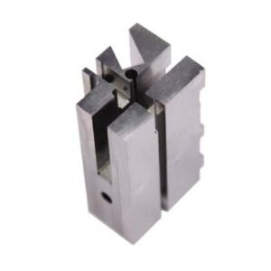




Why Engineering Teams Source Replacement Mold Inserts with SUUXIANG
Drawing review, process planning, and inspection visibility for replacement insert projects with critical functional requirements.
Drawing-Led Review
We review drawings, models, material requirements, and application context before quoting to clarify manufacturability and production assumptions.
Practical DFM Input
DFM discussion identifies datum strategy, tool access, machining allowances, and EDM requirements before production commitments are made.
Integrated Process Routes
CNC machining, EDM, precision grinding, fitting, and inspection are planned around the geometry and critical features of each insert.
Critical-Dimension Planning
Critical dimensions, surface priorities, and inspection methods are aligned with the drawing and verified quality expectations before machining begins.
Revision Visibility
Project communication keeps drawing revisions, inspection requirements, and delivery information visible throughout the replacement mold insert manufacturing workflow.
Order-Matched Documentation
Final inspection documentation is prepared to match the order requirements and the verified inspection plan for the supplied components.
Drawing-Driven Mold and Machined Parts
Configure the process route around critical dimensions, material condition, functional interfaces, inspection requirements, and controlled revision history.

CNC Machining Services
Precision CNC machining services for drawing-based parts requiring coordinated milling, turning, EDM, grinding, fitting, and inspection. Review critical dimensions, datums, material condition, and machining access before confirming a production route.
Upload a Drawing
CNC Milling
Custom CNC milling services for prismatic parts, plates, inserts, pockets, and complex machined features. Tool access, clamping strategy, datum sequence, wall geometry, and finishing allowance should be reviewed against the drawing.
Upload a Drawing
CNC Turning
Precision CNC turning services for rotational parts such as pins, sleeves, bushings, shafts, and locating features. Diameter relationships, runout, concentricity, thread details, material condition, and inspection method should be defined before machining.
Upload a Drawing
5-Axis Machining
5-axis CNC machining supports parts with angled features, compound surfaces, and multiple machining faces where repositioning may affect accuracy or access. Feasibility depends on geometry, clamping, tool reach, tolerance priorities, and inspection strategy.
Upload a Drawing
Swiss & Micro Machining
Swiss machining and micro machining support small, slender, and detail-intensive components where deflection, burr control, concentricity, and handling require careful process planning. Submit dimensions, material, quantity, and functional mating context for review.
Upload a Drawing
Wire EDM Services & Sinker EDM Services
Wire EDM and sinker EDM services address hardened materials, narrow slots, internal corners, fine profiles, and features inaccessible by conventional cutting. Wire path, electrode design, recast-layer considerations, finishing requirements, and inspection criteria guide planning.
Upload a Drawing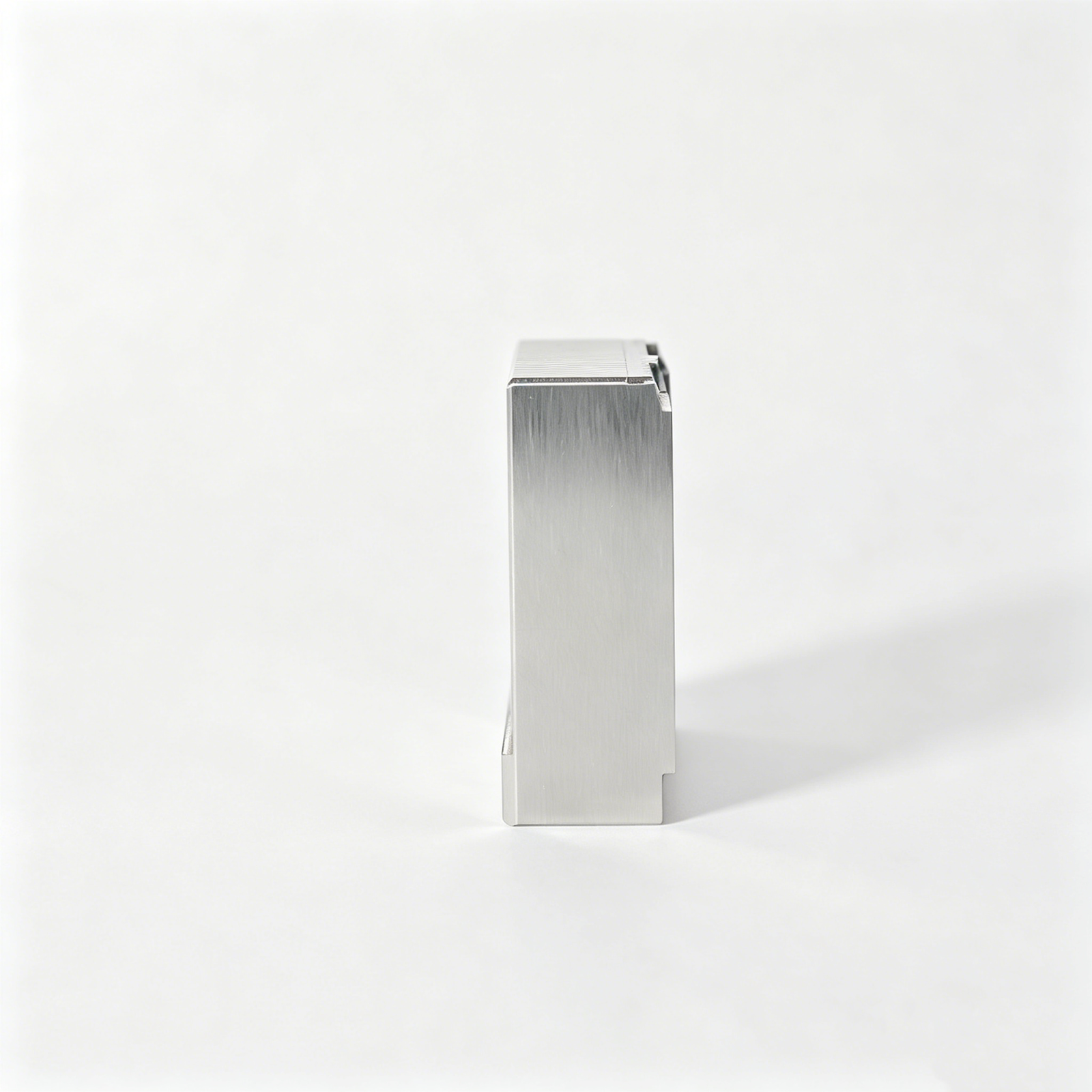
Precision Grinding
Precision surface and profile grinding supports controlled flatness, parallelism, profile accuracy, and finishing stock after machining or heat treatment. Define datum relationships, stock allowance, surface requirements, and any heat-treatment sequence before release.
Upload a Drawing
Mold Core Inserts & Mold Cavity Inserts
Precision mold core and cavity inserts are produced from customer drawings and matched to the required mold interface. Review shutoff geometry, cooling or vent features, steel condition, cavity surface needs, critical dimensions, and fitting expectations.
Upload a Drawing
Ejector & Ejection Components
Ejector pins, sleeves, and ejection components are evaluated for fit, guidance, bearing length, clearance, surface condition, and wear considerations. Provide mating-part dimensions and functional ejection requirements to support a suitable manufacturing plan.
Upload a Drawing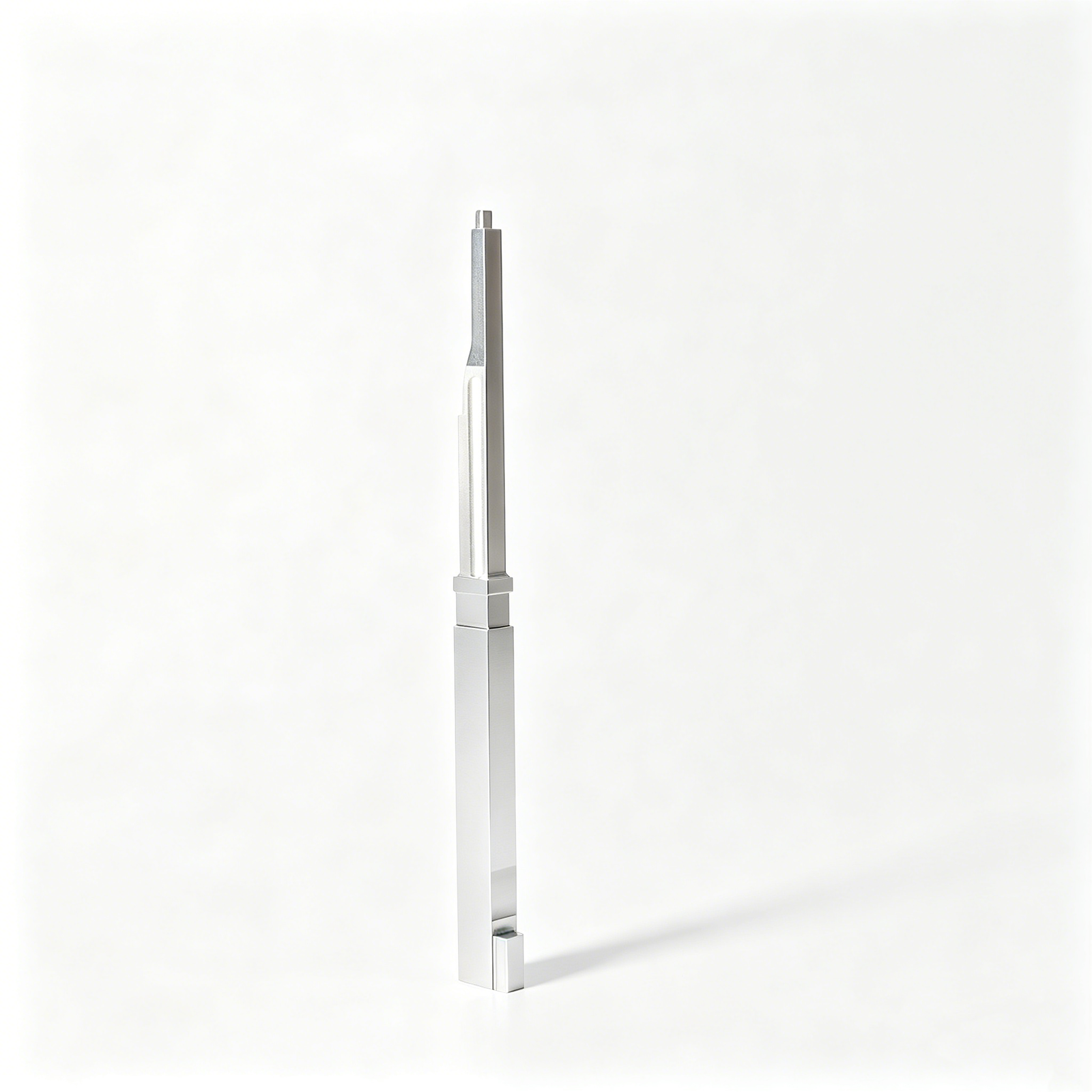
Core Pins, Guide & Locating Components
Core pins, guide pins, and locating components require control of diameters, shoulders, engagement lengths, datum relationships, and mating fits. Material, hardness, surface treatment, and assembly context should be documented with the RFQ.
Upload a Drawing
Slides, Lifters, Gates & Mold Accessories
Mold slides, lifters, gates, and accessories are configurable components requiring attention to travel, shutoff faces, wear areas, guiding, interference risk, and fitting sequence. Drawings should identify functional interfaces and critical assembly dimensions.
Upload a Drawing
Connector Mold Components
Precision connector mold components support tooling features where pitch, alignment, fine details, insert relationships, and repeatable mating geometry matter. Review part geometry, material, EDM needs, polishing requirements, and inspection priorities before production.
Upload a Drawing
Stamping Die Components
Precision stamping die components are planned around die-set interfaces, cutting or forming geometry, clearance relationships, wear surfaces, material condition, and heat-treatment sequence. Provide the component drawing and its mating or strip-process context when relevant.
Upload a Drawing
Injection Mold Components for MIM, CIM & Overmolding
Injection, MIM, CIM, and overmolding tooling components are assessed within verified production scope. Drawing review should address parting and shutoff features, insert interfaces, material behavior, molding application, surface needs, and inspection requirements.
Upload a Drawing
Machining Materials
CNC machining materials are selected against drawing requirements, application loads, corrosion exposure, heat treatment, machinability, and dimensional stability. State the specified grade, material certificate needs, and any approved alternatives before quotation.
Upload a Drawing
Surface Finishes & Heat Treatment
Surface finishing and heat treatment are specified according to function, wear, corrosion resistance, appearance, and dimensional risk. Identify required process, thickness or hardness criteria where applicable, masked areas, post-treatment grinding, and documentation expectations.
Upload a Drawing
Quality, Metrology & Documentation
Precision inspection, metrology, and quality documentation are planned from critical dimensions, datums, tolerances, and order-specific reporting needs. Clarify inspection methods, sample quantity, report format, traceability expectations, and revision-controlled drawing status.
Upload a Drawing
Prototyping & Low-Volume Production
Rapid prototyping and low-volume manufacturing support drawing-based validation, bridge quantities, replacement components, and controlled production batches. Provide quantity, target date, material, revision status, critical features, and required inspection evidence for review.
Upload a DrawingMaterials Considered for Mold Insert Projects

Pre-Hardened Tool Steel
A practical option for many replacement mold inserts where stable machining and moderate wear resistance are required. Grade selection, hardness condition, cavity geometry, polishing needs, and critical dimensions should be reviewed against the drawing.

Hardenable Tool Steel
Considered for inserts exposed to higher wear, shutoff contact, or demanding surface requirements. The machining plan must account for heat-treatment distortion, EDM or grinding allowance, datum protection, and final inspection method.

Stainless Tool Steel
Used when corrosion resistance or a specific polishing requirement affects the insert decision. Material availability, heat-treatment condition, surface finish, mating environment, and dimensional control are confirmed during drawing-led DFM review.

Copper Alloy Inserts
Evaluated for localized thermal-management needs where the application supports a conductive alloy solution. Design review should address insert retention, strength, cooling layout, mating surfaces, machining access, and inspection priorities.

Engineering Material Options
Specialty alloys or engineering materials may be considered for application-specific replacement mold inserts. Submit material specifications, operating conditions, quantity, and quality expectations so SUUXIANG can assess the proposed process route.
Precision Processes for Replacement Mold Inserts

CNC Milling
CNC milling establishes insert profiles, pockets, shutoff geometry, and accessible 3D features. Tool access, corner radii, stock allowance, and datum locations are reviewed so subsequent EDM or grinding operations protect critical geometry.

CNC Turning
CNC turning produces concentric diameters, shoulders, bores, and locating features on rotational replacement mold inserts. Drawing review confirms the datum scheme, runout expectations, and any finishing allowance required before fitting or inspection.

Wire EDM
Wire EDM creates through profiles, narrow slots, and precision contours where conventional cutter access is limited. The wire path, start-hole strategy, corner requirements, and reference surfaces should be defined before programming and measurement planning.

Sinker EDM
Sinker EDM forms deep cavities, sharp internal details, and complex geometry that cannot be reached efficiently by milling. Electrode design, spark allowance, surface requirements, and post-EDM finishing are coordinated against the approved drawing.


Fitting and Inspection
Fitting verifies how the replacement insert interfaces with its pocket, mating components, and functional references. Inspection follows the agreed critical-dimension plan, with revision status and requested reports kept aligned to the order.
Replacement Mold Inserts: Mating Features

Guide Locating Elements
Guide pins, bushes, keys, and locating features establish repeatable position between replacement mold inserts and their mating plates. Define datum references, engagement geometry, and service-clearance requirements on the drawing for review.

Ejector Interface Parts
Ejector pins, sleeves, return interfaces, and clearance features can be coordinated with the insert design. Share ejection travel, contact locations, and critical cosmetic surfaces to evaluate access, fitting, and inspection needs.

Gate Detail Features
Gate inserts and localized feed features may require EDM, grinding, or controlled transitions at the molding surface. Provide gate type, resin context, surface requirement, and datum strategy for a manufacturability discussion.

Fastener Interface Features
Threaded holes, dowel locations, clamp faces, and counterbores connect inserts to the surrounding mold structure. Drawing review should confirm thread specification, installation direction, tool access, and dimensional relationships to mating components.

Connector Tooling Details
Connector-tooling inserts can incorporate fine cavities, terminal-related geometry, and alignment references. Include the 2D drawing, 3D model when available, mating-part context, and critical dimensions to support process planning and inspection.
Replacement Mold Inserts, Built From Drawings
Established in 2010 in Chang’an Town, Dongguan, SUUXIANG is the sole public-facing brand of Dongguan SuuXiang Precision Mold Co., Ltd., founded by XiaoCheng Huang. We help international engineering, sourcing, and quality teams turn drawings and specifications into inspected replacement mold inserts, precision mold components, connector tooling, die components, and custom machined parts.
Our work is drawing-driven: DFM and critical-dimension review come before quotation and production commitments. Process planning can combine CNC milling and turning, multi-axis machining, wire EDM, sinker EDM, precision grinding, fitting, and inspection according to the part geometry, material requirement, datum strategy, and quality plan.
What distinguishes SUUXIANG is disciplined communication around manufacturability, machining access, EDM strategy, grinding allowance, inspection method, and revision control. Rather than treating components as a generic catalogue, we assess each inquiry against its application, mating features, quantity, delivery target, and documentation requirements before defining a responsible production route.

Replacement Mold Inserts, Protected at Critical Dimensions
DFM Starts at the Datum
Replacement mold inserts are reviewed against the drawing, 3D model, mating features, and intended datum scheme before quotation. This helps identify tolerance-stack exposure, tool-access constraints, and dimensional priorities that must be controlled through the selected process route.
- Confirm functional datums and critical-to-quality dimensions
- Review mating interfaces, shutoff areas, and reference surfaces
- Identify machining access and sequence-related risks
- Align drawing revisions before production planning

EDM Strategy for Difficult Geometry
When narrow ribs, internal corners, fine details, or inaccessible profiles require EDM, SUUXIANG plans the electrode or wire path alongside the machining route. The discussion focuses on geometry, finish expectations, datum transfer, and downstream fitting rather than treating EDM as an isolated operation.
- Assess wire-EDM versus sinker-EDM suitability
- Plan electrode access and reference locations
- Consider finish requirements and subsequent polishing
- Maintain dimensional intent through process handoffs

Grinding and Fitting Allowance
Replacement inserts often depend on controlled stock for heat treatment, grinding, and final fitting. SUUXIANG reviews where machining allowance is needed, which surfaces establish final location, and how the insert will interface with the existing mold assembly before commitments are made.
- Define surfaces reserved for finish grinding
- Review heat-treatment sequence and distortion risk
- Plan fitting surfaces and locating relationships
- Protect functional clearances at mating features

Inspection With Revision Traceability
Inspection planning is tied to the order, drawing revision, and agreed critical features for each replacement mold insert project. Measurement methods and reporting needs are clarified early so final documentation reflects the verified inspection plan and supports supplier-quality review.
- Identify features requiring dimensional verification
- Agree inspection methods and report requirements
- Keep drawing revisions visible through coordination
- Match final records to the approved order scope

Why Drawing Review Matters Before Replacement-Insert Quoting
Use these project controls to turn a replacement-insert drawing into inspectable, revision-managed production work.
← Swipe left or right to view →
Replacement Mold Inserts: From Drawing Review to Shipment
A drawing-led workflow that keeps critical dimensions, process decisions, inspection expectations, and revision status visible before production commitments are made.
RFQ and Drawing Review
We review 2D drawings, available 3D models, material, quantity, application context, target delivery date, and specified dimensional, surface, and reporting requirements.
DFM and Process Planning
Critical dimensions, datums, tolerance stack, tool access, heat-treatment sequence, grinding allowance, electrode needs, wire paths, and inspection methods are clarified before quotation.
Machine and EDM Production
Replacement mold inserts move through the planned CNC machining, turning, multi-axis work, wire EDM, sinker EDM, and controlled intermediate checks appropriate to the part.
Grinding and Precision Fitting
Grinding stock, mating relationships, locating features, shutoffs, and fit-critical surfaces are addressed through the defined finishing route, with revision information maintained throughout.
Inspection and Documentation Review
Finished parts are checked against the agreed inspection plan, focusing on critical dimensions, datum-related features, surface requirements, and documentation that matches the verified order.
Packing and Shipment Coordination
After final review, parts are packed for protection and delivery coordination follows the confirmed order requirements, with shipment details communicated through the project workflow.
How to Source Replacement Mold Inserts
A drawing-led process that aligns manufacturability, quality expectations, and delivery requirements before production begins.
Send Your Drawing Package
Upload the 2D drawing and available 3D model, then identify the replacement mold insert application, mating features, revision status, and required quantity.
Define Critical Requirements
Specify material, heat treatment, critical dimensions, datums, surface requirements, inspection documentation, target delivery date, and any assembly or molding constraints.
Review DFM and Quotation
Confirm the proposed machining, EDM, grinding, and inspection route, including tool access, machining allowances, clarification items, quotation scope, and sampling needs.
Approve Production Details
Resolve drawing revisions and acceptance criteria before release, so replacement mold inserts proceed under an agreed plan with visible project and delivery coordination.
SUUXIANG Customer-Evidence Publication Standard
Replacement Mold Inserts: Customer Project Feedback and Case Evidence
Customer-approved project feedback will be published here only after outcome records, documentation scope, and permission to identify the project have been verified.
Case evidence will be added when the drawing revision, inspection requirements, delivery coordination, and customer approval can be documented without disclosing controlled project information.
SUUXIANG publishes customer feedback only where the stated outcome and supporting project records are available for review and approved for public use.
Replacement Mold Inserts FAQ
Practical answers for teams sourcing drawing-led replacement inserts and related precision mold components.
What information do you need to quote replacement mold inserts?
Can you manufacture replacement mold inserts from an existing sample?
What materials can be considered for replacement mold inserts?
What tolerances can SUUXIANG hold on replacement mold inserts?
Is there a minimum order quantity for custom mold inserts?
How long do replacement mold inserts take to produce?
Can I receive an inspection report with my mold insert order?
How are drawing revisions and IP handled for replacement mold inserts?
The Complete Guide to replacement mold inserts
Use a practical decision framework to specify replacement mold inserts, evaluate supplier engineering and inspection capability, control lifecycle cost, and avoid fit, material, documentation, and qualification mistakes before production.
1. What Are replacement mold inserts?
One replacement mold insert is a drawing-based, removable precision component made to restore, alter, or sustain a defined working area of an existing tool. It can replace a worn shutoff, damaged core detail, cavity feature, locating surface, or another localized function without remanufacturing the complete tool.
Two terms should remain separate: a replacement insert stays in the mold and forms, guides, cuts, or supports production; a molded-in insert becomes permanently enclosed within the finished product. It is also not a complete mold assembly, because its fit, datum relationship, interface, and service purpose are defined against the existing tooling.
SUUXIANG reviews replacement work from the current drawing, 3D data when available, revision history, application context, and inspection expectations. This scope can apply to injection molds, connector tooling, and stamping dies where a controlled spare supports damage recovery, geometry revision, localized wear management, or faster planned changeover.
2. How replacement inserts evolved
Two-piece core-and-cavity constructions concentrated the molding surface in large, fixed blocks. When a localized feature wore, corroded, changed, or was damaged, repair could require reworking a much larger tool area and re-establishing its relationship to the mold base.
By the late design stage, modular insert strategies separated high-risk or variant-defining geometry from the parent core or cavity. A replaceable insert can improve service access and support product variants, but every pocket, seat, anti-rotation feature, shutoff surface, and cooling constraint must preserve the intended functional relationship.
Three records govern a credible replacement today: the released legacy drawing, the datum scheme, and the current revision history. SUUXIANG should review these with the 3D model, mating-component context, wear evidence, material and heat-treatment requirements, then agree the inspection method before machining; a dimension copied without its datum or revision can fit on paper yet fail in assembly or molding.
3. Types of replacement mold inserts
Replacement mold inserts should be classified by the interface they restore, not only by outside shape. A replacement drawing package must identify the insert’s datum scheme, mating pocket, and functional surface.
Cavity And Core Inserts

Cavity and core inserts form the molded geometry and are commonly replaced after damage, wear, corrosion, or an engineering revision.
Critical inputs include shutoff faces, parting-line relation, cooling clearances, steel-safe areas, finish, and all pocket datums.
Pins Sleeves And Moving Inserts

Pins and sleeves create holes, ejection features, or localized cores; sliders and lifters form undercuts and moving shutoffs.
Replacement data must define diameters, fits, stroke limits, anti-rotation features, return interfaces, wear faces, and the mating component.
Identification Venting And Tool Inserts

Date or identification inserts support part traceability; venting inserts release trapped gas; connector and stamping-tool inserts create specialized profiles.
Send marking layout, orientation, vent path and depth requirements, contact geometry, strip direction, die clearance, and mating-stack dimensions.
4. Materials for replacement mold inserts
HRC hardness alone does not select an insert material. The approved drawing, resin, filler loading, expected production volume, cooling environment, and operating temperature must govern the final callout.
| Material Family | Primary Strength | Key Limitation | Typical Fit |
|---|---|---|---|
| Tool steel | Toughness, wear | Corrosion risk | General production inserts |
| Stainless steel | Corrosion, polish | Lower conductivity | Wet or corrosive service |
| Copper alloy | Heat transfer | Lower wear resistance | Hot spots |
| Carbide | Abrasive wear | Brittleness | Filled-resin contact areas |
Steel Selection Logic
H13-type tool steel balances toughness and heat-checking resistance for demanding molding conditions.
P20-type prehardened steel suits lower-wear service; stainless steel adds corrosion resistance where resin gases, humidity, or water exposure matter.
Conductivity And Wear Trade-Offs
Copper alloys transfer heat faster than common tool steels, helping isolated hot areas, but need protection from wear and deformation.
Carbide resists severe abrasion from filled resins, yet its brittleness requires supported geometry and controlled fitting.
Drawing-Controlled Verification
48–52 HRC may be appropriate for a hardened steel insert, but hardness, polishability, coating, heat treatment, and inspection criteria require drawing approval.
SUUXIANG should confirm material certificates, heat-treatment sequence, critical dimensions, and mating conditions before machining.
5. Engineering options for replacement mold inserts
Two interface decisions—geometry and location—determine whether a replacement insert restores fit without creating a new stack-up risk. SUUXIANG reviews the drawing, datums, mating conditions, access, and inspection requirement before selecting a process route.
| Option | Primary Benefit | Review Before Machining |
|---|---|---|
| Interchangeable interface | Faster controlled changeover | Datums, retention, removal clearance |
| Cooling or venting | Thermal control or gas release | Steel thickness, sealing, cleanout |
| Coating or finish | Wear or release management | Allowance, polish, repair route |
| Laser serialization | Traceability | Location, revision format, readability |
Interface And Changeover
One common-change interface uses a repeatable seating face plus defined location features; keyways, flats, or dowel arrangements can prevent a directional or round insert from rotating. Retention-screw access and removal clearance must be checked against adjacent cooling, ejectors, and mold plates.
- Match replacement datums to the original tool
- Specify removal method and screw access
- Review wall strength around pockets
Thermal And Release Features
Two functional provisions—cooling and venting—can improve cycle stability or gas evacuation, but both reduce available steel. Channel position, sealing land, vent depth, resin behavior, and cleaning access require mold-specific review before machining.
- Cooling needs pressure-test requirements
- Vents need a cleaning strategy
- Texture and polish affect release
Wear And Identification

One coating or finish choice should follow the wear mechanism, resin, mating surfaces, and later repair plan; it is not a universal upgrade. Laser-marked part numbers, revision codes, and serial identifiers support controlled changeovers when they remain outside sealing and cosmetic areas.
- Define marking location on the drawing
- Link serial numbers to inspection records
- Confirm coating thickness allowances
6. Quality elements in replacement mold inserts
Three interfaces determine whether replacement mold inserts fit: the locating datum, sealing boundary, and molded surface. Define each from the mold assembly, not from an isolated replacement part.
Datums And Fit
Two or three functional datums should locate the insert and identify orientation.
0.01 mm matters only when tied to a critical feature, clearance, or tolerance stack; show location, perpendicularity, and mating dimensions on the drawing.
- Identify primary, secondary, and tertiary datums
- Mark anti-rotation features and assembly direction
- Specify fit dimensions at the interface
Sealing And Surface Details
0.02 mm mismatches can create flash or witness lines at a sealing boundary.
1° draft, matching radii, edge breaks, texture direction, vent land, and vent depth should be explicitly called out where they affect molding.
- Define shutoff and sealing surfaces
- State radius and draft requirements
- Call out vent geometry separately
Heat Treatment And Verification
HRC requirements belong with the specified material and heat-treatment condition, not as a generic note.
100% critical-dimension results, hardness evidence when required, revision identification, and mating-component verification should be requested before shipment.
- Compare the insert against the mating core or cavity
- Review inspection method and datum setup
- Confirm revision-controlled documentation
7. Choosing a replacement mold inserts supplier
A replacement-insert supplier should be evaluated against the installed mold interface, not a loose-part drawing alone. SUUXIANG begins with drawing review, application context, and an agreed inspection plan before committing a process route.
Review The Installed Interface
The 2D drawing should identify datums, shutoff faces, locating features, orientation, mating parts, and any cooling or ejection clearance. Ask how the supplier will verify fit after heat treatment, EDM, grinding, and final fitting.
- Which dimensions control interchangeability in the mold?
- What is the datum transfer from insert to mold base?
- Which installed clearances require evidence?
Align Acceptance Evidence
The first-article agreement should define material traceability, critical dimensions, inspection methods, report format, revision level, and approval hold point. Engineering, procurement, and supplier quality should sign one acceptance matrix before production.
- Material and heat-treatment records
- Dimension-specific metrology results
- Revision-controlled drawing acknowledgment
- Sample approval and packaging requirements
Test Project Transparency
The RFQ response should state the proposed CNC, EDM, grinding, and inspection sequence, plus risks requiring customer decisions. Ask for a dated lead-time plan that separates drawing clarification, material preparation, machining, inspection, approval, and shipment.
- Who owns revision communication?
- When will exceptions be raised?
- How are parts protected during shipment?
8. Replacement mold inserts: buyer mistakes
Replacement orders fail most often before machining begins: an old revision, incomplete interfaces, or an undefined acceptance plan can turn a nominally correct insert into unusable tooling. Release only after the drawing package, mating context, process requirements, and inspection criteria agree.
Control The Revision
Revision-controlled 2D drawings and native or neutral 3D models prevent a supplier from reproducing superseded geometry. Include the revision identifier, change summary, and mating-part dimensions; otherwise, fit, shutoff, or locating features may conflict.
Before purchase-order release, freeze the approved data set and identify the controlling document. Require written acknowledgement of every revision and any drawing-versus-model discrepancy.
Define Functional Requirements
Nominal dimensions without tolerances, datums, surface callouts, or critical-feature labels cannot establish acceptance. Specify the dimensions that control sealing, alignment, ejection, and interchangeability, plus the inspection method.
Material names alone are incomplete when grade, hardness range, heat-treatment condition, coating, and corrosion expectations affect machining and wear. State the required condition and confirm the process sequence before release.
Use The Correct Insert Term
Replacement mold inserts are tool components fitted into a mold; molded-in inserts are components encapsulated in the finished plastic part. Confusing these terms can send procurement toward the wrong process and supplier scope.
Before issuing an RFQ, provide photographs or assembly views that show where the part sits and how it is retained. This distinction is consistent with https://icomold.com/capabilities/injection-molding-processes/insert-molding.
Buy Evidence, Not Price
A lowest-price quote may omit EDM strategy, grinding stock, fitting work, inspection records, or revision control. Compare quotations against the same drawing package and documented deliverables.
Before release, define required reports, sample quantity, packaging, delivery date, and communication checkpoints. Select the supplier whose process route and evidence address the actual failure risks, not merely the lowest unit price.
9. Launching a replacement-insert program
One controlled workflow prevents a replacement insert from becoming an undocumented geometry change. It should connect the failure record, released data, inspection evidence, and reorder history.
Define The Technical Need
Step 1: Design and tooling document the failure mode, wear location, revision objective, and mating context.
Step 2: Quality identifies critical-to-function dimensions, datums, surfaces, and acceptance method; retain marked samples when available.
Review Before Purchase
Step 3: Purchasing sends the controlled 2D drawing, 3D model, quantity, material, heat-treatment requirement, and target date.
Step 4: SUUXIANG can return DFM feedback covering tool access, EDM or grinding route, allowances, risks, quotation assumptions, and proposed inspection plan.
Validate And Release
Step 5: Quality approves material evidence and the inspection plan before production, then reviews first-article results against released requirements.
Step 6: Program management releases any approved revision, records disposition of prior versions, and authorizes purchasing to reorder.
Preserve Reorder Records
Step 7: Keep the drawing revision, CAD file, material and heat-treatment specification, inspection report, and approved deviations together.
Step 8: Record insert location, mold identification, supplier part reference, quantity, delivery history, and change owner for future replacement mold inserts.
10. Replacement mold inserts pricing and cost
1 replacement insert quotation should separate part-making scope from risk-bearing scope: material grade, envelope size, geometry, tolerances, heat treatment, finish, inspection, quantity, and requested delivery date.
2 quotations with the same unit price can differ materially in included inspection, revision handling, fitting assumptions, packaging, and expedited routing. Compare the complete manufacturing and documentation scope before selecting the lowest figure.
| Cost driver | Cost effect | Buyer question |
|---|---|---|
| Material grade and heat treatment | Changes stock, machining route, distortion control | Is the specified grade and hardness included? |
| Size and geometry | More setups, tool access, EDM or grinding time | Which features drive cycle time? |
| Tolerance and finish | Adds controlled machining, polishing, and measurement | Which dimensions are critical-to-quality? |
| Inspection and documentation | Adds measurement planning and reporting effort | What report, datum scheme, and traceability are included? |
| Quantity and urgency | Spreads setup cost; acceleration may add capacity cost | What is the price and lead-time basis for each quantity tier? |
Upload Your Drawing for Replacement Mold Inserts
Share material, quantity, critical dimensions, inspection requirements, and target delivery date for a disciplined engineering review before quotation.