
Connector Mold Inserts Built From Your Drawings
SUUXIANG reviews critical dimensions, then plans CNC machining, EDM, grinding, and inspection for connector mold inserts.
Featured Connector Mold Insert Components









Related Drawing-Defined Components and Quotation









Why Engineering Teams Choose SUUXIANG for Connector Mold Inserts
Drawing-led planning keeps critical requirements visible from DFM review through machining, EDM, grinding, inspection and delivery coordination.
Drawing-First DFM Review
We review datums, critical dimensions, tool access and manufacturability before quotation, helping teams identify open technical decisions early.
Critical Dimension Planning
Priority dimensions, surface requirements and tolerance relationships are discussed against the drawing so machining and inspection planning share the same intent.
Coordinated Process Routes
CNC machining, EDM, grinding and fitting are planned as connected steps, with allowances and access considerations reviewed for each feature.
Inspection Plan Alignment
Measurement expectations are defined around critical features, datum strategy and required reporting, so final documentation follows the agreed inspection plan.
Visible Revision Control
Drawing revisions, project discussions and delivery information remain traceable, reducing the risk of producing connector mold inserts to superseded requirements.
Technical Communication
Engineering and sourcing teams receive practical questions about materials, heat treatment, quantities, quality expectations and mating-component context before production commitments.
Connector Mold Insert and Tooling Families
Drawing-driven manufacturing categories for connector tooling teams that need controlled process selection, critical-dimension review, and inspection-ready parts.

CNC Machining Services
Precision CNC machining services translate approved drawings into custom components through planned milling, turning, EDM, grinding, fitting, and inspection routes. Review focuses on datums, critical dimensions, material condition, machining access, and reporting requirements before production commitments are made.
Upload a Drawing
CNC Milling
Custom CNC milling services support prismatic and contoured mold and tooling components, including pockets, channels, mating faces, and locating features. Tool access, clamping strategy, corner radii, stock condition, and tolerance relationships should be reviewed against the drawing.
Upload a Drawing
CNC Turning
Precision CNC turning services produce rotational features such as pins, sleeves, bushings, inserts, and locating elements. Diameter, concentricity, runout, thread details, surface requirements, and subsequent grinding or heat-treatment allowances must be defined in the production plan.
Upload a Drawing
5-Axis Machining
5-axis CNC machining helps reach angled, contoured, and compound features while reducing unnecessary setups on suitable parts. A drawing review confirms fixture access, tool reach, datum transfer, corner conditions, and whether multi-axis machining supports the required inspection strategy.
Upload a Drawing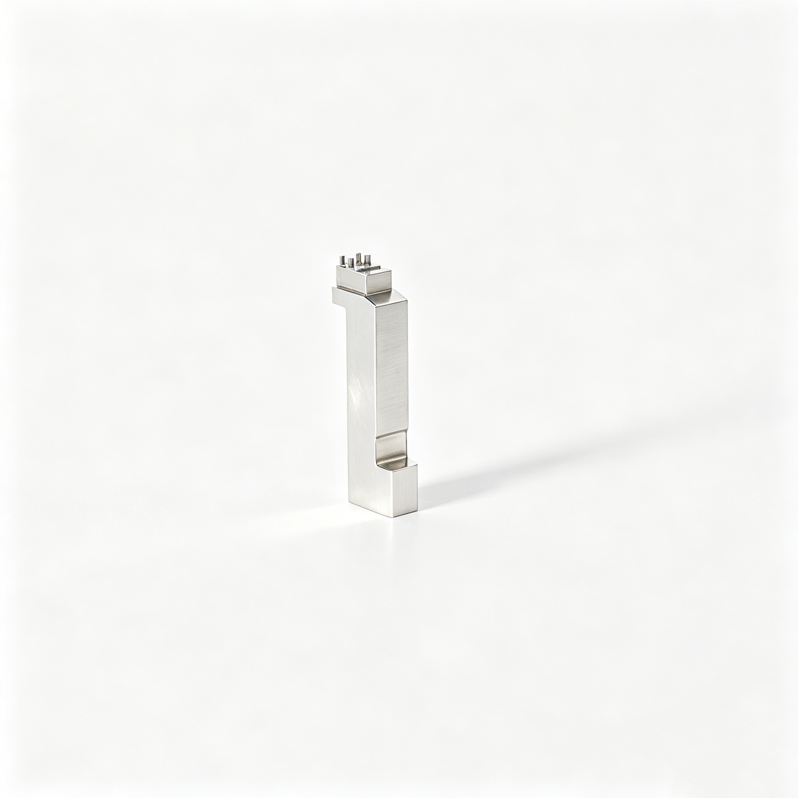
Swiss & Micro Machining
Swiss machining and micro machining address small, slender, and feature-dense connector-tooling parts where support, concentricity, and burr control matter. Submit dimensions, material, quantity, critical features, and any mating-component context for process review.
Upload a Drawing
Wire & Sinker EDM
Wire EDM and sinker EDM services create narrow slots, sharp internal geometry, hardened features, and difficult-to-machine details when conventional tools cannot provide suitable access. Electrode design, wire path, flushing, recast-layer considerations, and finishing requirements should be agreed before release.
Upload a Drawing
Precision Grinding
Precision surface and profile grinding establishes controlled flatness, parallelism, profile geometry, and final size on appropriate components. Grinding stock, heat-treatment sequence, datum surfaces, surface finish, and measurement method need to be aligned with the drawing requirements.
Upload a Drawing
Mold Core & Cavity Inserts
Precision mold core and cavity inserts are manufactured as configurable components for defined part geometry, material condition, cooling or venting needs, and mating interfaces. Review should cover steel selection, shrinkage-related requirements, EDM details, polishing needs, and critical shutoff surfaces.
Upload a Drawing
Ejector & Ejection Components
Ejector pins, sleeves, and ejection components require controlled fit, straightness, bearing surfaces, and interface conditions to support dependable mold movement. Drawings should identify material, hardness or treatment needs, working clearances, surface requirements, and any wear-sensitive features.
Upload a Drawing
Core Pins, Guide & Locating Components
Core pins, guide pins, and locating components establish repeatable geometry and alignment between mold elements. Manufacturing review considers pin diameter, engagement length, concentricity, fit class, heat treatment, grinding allowance, and the datum relationship to adjoining components.
Upload a Drawing
Slides, Lifters, Gates & Mold Accessories
Mold slides, lifters, gates, and accessories are produced to drawing-defined travel, shutoff, locating, and interface requirements. The process route should account for motion surfaces, wear areas, machining access, heat treatment, fitting requirements, and inspection points.
Upload a Drawing
Connector Mold Components
Precision connector mold components support high-density, fine-feature tooling where pitch, alignment, pin or cavity geometry, and repeatable assembly relationships are decisive. Provide drawings, 3D data, material requirements, mating details, and critical dimensions for a focused DFM review.
Upload a Drawing
Stamping Die Components
Precision stamping die components are made for drawing-defined cutting, forming, guiding, and locating functions. Material, hardness, edge condition, clearance relationships, grinding requirements, and wire-EDM access must be evaluated in relation to the complete die assembly.
Upload a Drawing
Injection Mold Components, MIM, CIM & Overmolding Tooling
Injection, MIM, CIM, and overmolding tooling work is evaluated within verified production scope for component geometry, material behavior, inserts, gating, and mold-interface requirements. Project discussion should identify process-specific shrinkage, thermal, wear, and dimensional risks before manufacture.
Upload a Drawing
Machining Materials
CNC machining materials are selected against drawing requirements for strength, wear, corrosion resistance, machinability, heat treatment, and inspection needs. State the required material grade, condition, approved equivalent policy, certification expectations, and application context in the RFQ.
Upload a Drawing
Surface Finishes & Heat Treatment
Surface finishing and heat treatment are planned around functional surfaces, wear behavior, corrosion needs, dimensions, and post-process inspection. Specify the required treatment or finish, masked areas, thickness or hardness criteria, cosmetic priorities, and whether final grinding is expected.
Upload a Drawing
Quality, Metrology & Documentation
Precision inspection, metrology, and quality documentation are matched to the order’s critical dimensions and agreed inspection plan. Define required reports, datum references, sampling expectations, traceability needs, revision level, and any customer-specific measurement or documentation format.
Upload a Drawing
Prototyping & Low-Volume Production
Rapid prototyping and low-volume manufacturing support drawing-driven evaluation, tooling development, qualification, and controlled repeat work. A useful RFQ identifies quantity, material, revision maturity, critical dimensions, inspection needs, target delivery, and the decision the parts must support.
Upload a DrawingConnector Mold Inserts: Project-Dependent Tool Steels

Pre-Hardened Tool Steel
A practical option for connector tooling components where balanced machinability and moderate service demands are required. Confirm required hardness, polishing needs, and wear exposure from the drawing before defining the machining and inspection route.

Through-Hardening Tool Steel
Used for inserts, cores, and wear features needing greater hardness after heat treatment. Critical dimensions require planned machining allowance, heat-treatment sequence, grinding stock, and final inspection methods to control distortion risk.

Corrosion-Resistant Tool Steel
Considered when resin chemistry, humidity, storage conditions, or molding environment create corrosion concerns. Material grade, heat treatment, surface condition, and mating-part requirements should be reviewed together rather than specified independently.

High-Wear Tool Steel
Suitable for localized gates, slides, core details, and other connector mold features subject to repeated abrasion or contact. EDM strategy, finishing allowance, hardness target, and replacement-interface datum control require drawing-based confirmation.

Tungsten Carbide Grades
A project-dependent choice for compact wear areas, fine pins, and demanding forming details where stiffness and wear resistance matter. Grade selection, geometry, joining method, grinding access, and inspection criteria must be assessed before quotation.
Connector Mold Inserts: Machining and EDM Processes

CNC Milling
CNC milling establishes profiles, pockets, locating faces, and accessible cavity features for connector mold inserts. Tool access, datum references, machining allowance, and later EDM or grinding requirements are reviewed before the process route is confirmed.

Wire EDM
Wire EDM produces precise through-features, narrow slots, and complex internal profiles where conventional cutter access is limited. The wire path, start-hole position, corner requirements, and datum relationship should be defined against the drawing and inspection plan.

Sinker EDM
Sinker EDM forms detailed cavities, ribs, and deep geometric features that require electrode access rather than direct cutting. Electrode strategy, spark-gap allowance, surface requirements, and downstream fitting needs are evaluated during DFM review.


Fitting Inspection
Fitting and inspection verify how mating connector-tooling components function together, with focus on critical dimensions, alignment, surface condition, and documented checks. SUUXIANG coordinates inspection evidence to the order-specific plan and revision level.
Functional Features for Connector Mold Inserts

Locating Features
Dowel bores, register faces, keys, and datum references help position inserts consistently within the mold base. Their geometry should be reviewed with the assembly datum scheme, fitting approach, and critical alignment requirements.

Guide Components
Guide pins, bushings, and wear interfaces support repeatable movement between mating tooling elements. SUUXIANG reviews clearance, lubrication provisions, material pairing, and accessible replacement details from the approved drawing package.

Fastening Provisions
Threaded holes, counterbores, clamps, and fastening seats secure inserts during molding and maintenance. Hole positions, thread specifications, engagement depth, and tool access should be defined alongside the surrounding component geometry.

Ejection Interfaces
Ejector-pin contacts, return-pin seats, ejector clearances, and relief features require coordination with part release and mold motion. The drawing review identifies critical locations, allowable witness marks, and inspection points before machining.

Identification Marking
Part numbers, revision marks, cavity identifiers, and orientation references can improve traceability during fitting, maintenance, and inspection. Marking method, location, character depth, and protected surfaces should be specified in the RFQ.
About SUUXIANG Connector Mold Inserts
Established in 2010, SUUXIANG is the public-facing brand of Dongguan SuuXiang Precision Mold Co., Ltd., based in Chang’an Town, Dongguan, Guangdong, China. We help global engineering and sourcing teams convert drawings, models, and quality requirements into inspected connector mold inserts, precision mold components, and custom CNC-machined parts.
Our work is coordinated around the process route each part requires: CNC milling and turning, multi-axis machining, wire or sinker EDM, precision grinding, fitting, and inspection. Before quotation and production, we review critical dimensions, datums, machining access, electrode or wire path needs, grinding allowance, material requirements, and revision details.
What distinguishes SUUXIANG is disciplined drawing review and visible project coordination. Rather than treating connector tooling as a generic catalog item, we align manufacturing and inspection planning with the part’s functional requirements, quantity, surface priorities, delivery target, and documentation needs. The result is a clearer path from RFQ to verified production evidence.

A Drawing-Led Process Comparison for Connector Mold Inserts
DFM and Datum Strategy
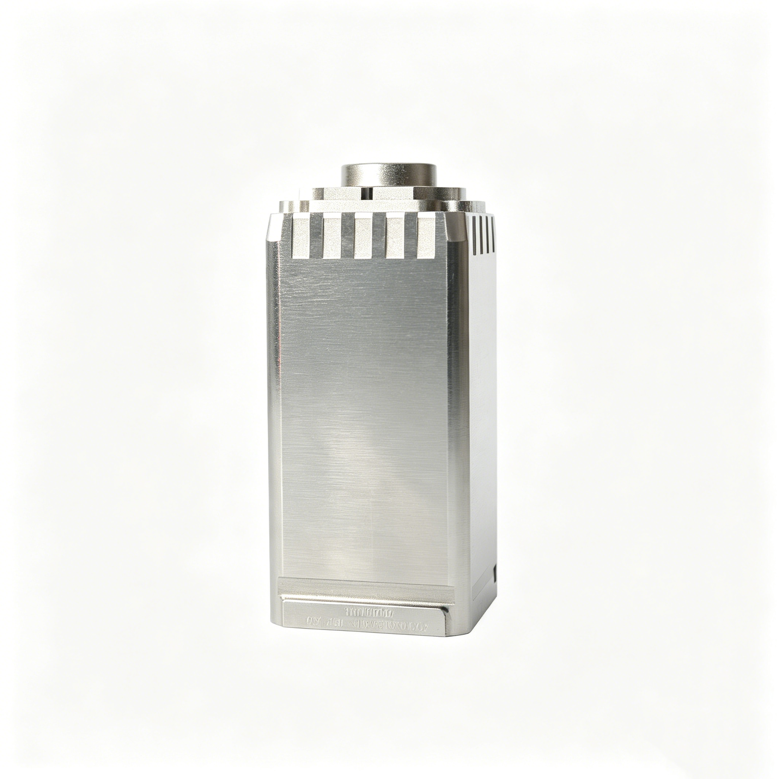
Before production planning, SUUXIANG reviews the drawing, model, mating context, critical dimensions, and datum scheme. The review identifies tolerance-stack risks, tool access constraints, and features that require a defined machining, EDM, or grinding sequence.
- Confirm functional datums and critical-to-quality dimensions
- Review wall conditions, shutoffs, and access limitations
- Align revision details before quotation and release
CNC and EDM Planning
Connector mold inserts often combine milled geometry with narrow slots, sharp internal details, or hard-to-reach profiles. SUUXIANG plans CNC machining, electrode strategy, wire paths, and EDM allowances around the approved drawing rather than assigning a generic process route.
- Match milling access to feature geometry and tool reach
- Define wire EDM or sinker EDM needs by profile
- Preserve stock where grinding or finishing follows

Grinding and Fitting Control
Precision surfaces depend on the relationship between heat treatment, machining allowance, grinding stock, and final fitting. For connector mold inserts, SUUXIANG evaluates these dependencies early so final surfaces and mating conditions can be checked against the intended assembly function.
- Plan grinding after relevant heat-treatment stages
- Protect datum relationships through finishing operations
- Review mating interfaces and fitting requirements

Inspection and Revision Traceability
Inspection planning is tied to the order’s drawing revision and agreed critical features. SUUXIANG coordinates dimensional verification, inspection methods, and required reporting so connector tooling components are released with documentation that matches the verified production plan.
- Identify dimensions requiring measured verification
- Match reporting needs to the approved inspection plan
- Keep drawing revisions visible through production coordination

Why Choose SUUXIANG for Connector Mold Inserts
A drawing-led workflow makes critical features, process decisions, inspection requirements, and revisions visible before production commitments.
← Swipe left or right to view →
Connector Mold Inserts Production Workflow
A controlled path from RFQ review through machining, inspection, and delivery coordination for drawing-based connector tooling components.
Review RFQ Package
We review drawings, models, material requirements, quantities, application context, target dates, and requested inspection documentation before defining a quotation basis.
Confirm DFM Priorities
Critical dimensions, datums, tolerance stacks, surface requirements, machining access, and likely EDM or grinding needs are clarified with the customer.
Plan Process Route
The team aligns material and heat-treatment sequence with CNC, wire EDM, sinker EDM, grinding, fitting, and inspection steps appropriate to the approved drawing.
Machine Critical Features
CNC machining establishes primary geometry, while EDM and grinding are applied where feature access, internal detail, finish, or dimensional control requires them.
Inspect And Document
Parts are checked against the agreed inspection plan, with measurement records and revision information matched to the order’s documented quality requirements.
Pack And Coordinate Delivery
After final release, components are packed for shipment and delivery details are coordinated against the confirmed order, documentation, and project communication requirements.
How to Work With SUUXIANG on Connector Mold Inserts
A structured workflow for reviewing requirements, confirming manufacturability, and coordinating inspected connector tooling components.
Submit Your Drawing
Send the 2D drawing and, when available, 3D model, along with application context so SUUXIANG can identify relevant connector mold insert features and tooling constraints.
Confirm Requirements
Define material, heat-treatment, quantity, target delivery, critical dimensions, datums, surface priorities, and inspection or reporting expectations before quotation commitments are made.
Review the Proposal
Review the proposed DFM findings, process route, machining access, EDM or grinding needs, inspection approach, revision status, and quotation or sampling details.
Approve Production Details
Approve the confirmed drawing revision, commercial scope, and sampling or production plan after open technical questions, quality expectations, and delivery coordination are resolved.
Receive Parts and Records
Receive parts with documentation aligned to the agreed inspection plan, then provide feedback or updated revisions for the next connector tooling requirement.
Connector Mold Inserts Certificates and Quality Documentation
Connector Mold Inserts Customer Feedback
Customer-approved testimonial slot: publish only after the customer confirms the quote, company attribution, role, project scope, and documented outcome for this connector tooling program.
Customer-approved case-study slot: include only verified evidence such as drawing revision control, inspection documentation, delivery milestone, or validated tooling result after written approval is received.
Customer-approved testimonial slot: use the customer’s exact approved language and a traceable project metric only when the underlying production and quality records support publication.
Connector Mold Inserts FAQ
Practical RFQ, quality, revision, and delivery questions for drawing-based tooling components.
What information do you need to quote connector mold inserts?
Can you make low-volume or prototype connector mold inserts?
Is there a minimum order quantity for connector mold inserts?
How long do samples or production parts take?
What inspection reports can be supplied with connector mold inserts?
How do you control drawing revisions and changes?
How are IP and confidential drawings handled?
How are payment, shipping, and delivery terms confirmed?
The Complete Buyer’s Guide to connector mold inserts
Use this decision framework to specify connector tooling, compare supplier capabilities, control DFM and inspection risk, and avoid costly mistakes in drawing-based precision mold-component sourcing.
1. What Are connector mold inserts?
One connector mold insert is a precision, replaceable tooling component installed within an injection mold to form, locate, support, or protect connector-specific geometry. It may create terminal cavities, pin passages, keying features, sealing details, or shutoff surfaces while the mold cycles.
Two items are often confused with it: an insert-molded electrical contact becomes part of the finished connector, while an insert is part of the production tool. A complete mold base is the structural frame carrying plates, guidance, cooling, and ejection; the insert is the functional element engineered for targeted replacement.
Three drawing controls usually determine whether a replacement insert works: pin geometry, cavity-detail location, and datums that establish alignment with adjacent tooling. Buyers are sourcing a controlled interchangeable component—not merely a machined block—so the RFQ should identify wear surfaces, mating parts, revision level, critical dimensions, material and heat-treatment requirements, and the inspection evidence required before release.
2. How connector mold inserts Evolved
Two manufacturing shifts changed connector tooling: repeatable CNC machining reduced dependence on hand-fitting, while wire EDM and sinker EDM made narrow slots, sharp internal forms, and hardened-steel details more controllable. The practical purchasing question became whether each critical feature had a defined machining, EDM, grinding, and inspection route rather than relying on bench correction.
Three pressures—miniaturized pitches, higher cavitation, and shorter engineering-change cycles—made monolithic cavity details less attractive. Modular, replaceable connector mold inserts let a toolmaker isolate wear-prone or revised geometry, preserving the surrounding mold base when a qualified replacement is fitted and rechecked.
Data-driven inspection extended this evolution beyond machining. Buyers should now request datum references, CTQ dimensions, measurement methods, revision status, and records linking the inspected insert to its drawing; insert placement accuracy remains a key validation concern in connector molding workflows (https://www.lsrpf.com/insert-molding).
3. Types of connector mold inserts
Connector mold inserts should be selected by the molded feature they create, not by a generic component label. The architecture must preserve steel support, molding access, datum control, and a practical replacement path.
| Insert Type | Molding Role | Main Exposure | Drawing Details |
|---|---|---|---|
| Core/cavity | Forms housing geometry | Thin steel, poor venting | Datums, draft, ribs |
| Terminal/pin | Forms contact features | Pin shift, flash | Centers, radii, spacing |
| Shutoff/slider | Releases undercuts | Galling, mismatch | Travel, angle, interference |
| Guide/locating | Sets repeatable position | Wear, runout | Fit, datum, runout |
| Wear/replaceable | Protects service areas | Erosion, abrasion | Retention, replacement datum |
Forming Features
Core and cavity inserts form housings, latch windows, and internal walls; deep ribs and thin steel raise deflection and venting risk.
Terminal and pin-forming inserts establish contact slots and pin spacing; provide pin centerlines, draft, root radii, and the molding datum.
Moving And Locating Features
Shutoffs and sliders release undercuts such as side windows; specify travel direction, shutoff angle, interference limits, and lubrication constraints.
Guide and locating inserts control repeatable mold-half or insert position; identify primary datums, fit class, and allowable runout.
Serviceable Wear Features
Wear inserts protect gates, shutoffs, and high-cycle contact areas; specify expected replacement interface, retention method, and requalification dimensions.
4. Materials for connector mold inserts
Three decision inputs—resin, cavity geometry, and planned shot volume—should drive material selection. Material is a process choice: it affects EDM response, grindability, polish retention, cooling behavior, and maintenance intervals.
| Family | Key Strength | Primary Limitation | Typical Fit |
|---|---|---|---|
| Pre-hardened steel | Stable machining, toughness | Lower wear resistance | Moderate volumes |
| Through-hardened tool steel | Wear resistance, polish potential | Heat-treatment distortion | Glass-filled resins |
| Stainless tool steel | Corrosion resistance | Grade-dependent polish and wear | Corrosive resin environments |
| Carbide | Exceptional wear resistance | Brittleness, difficult fitting | Localized high-wear features |
| Copper-based electrode | EDM machinability, conductivity | Consumable electrode | Fine EDM details |
Material Comparison
Five material families cover most connector-tooling decisions. Final grade, hardness, and heat-treatment sequence require application review.
Match Resin And Duty
Glass-filled and mineral-filled resins accelerate gate, shutoff, and pin wear; hardened tool steel or carbide may be justified at localized wear points.
High-polish optical or cosmetic surfaces need steel with predictable polishability, while corrosive resins favor stainless tool steel and a documented cleaning plan.
Plan Machining And Maintenance
EDM electrodes are consumable process tooling, not cavity-insert material; copper-based electrodes can support fine-feature sinker EDM when electrode strategy permits.
Tight-tolerance inserts need allowance for heat treatment, wire paths, grinding, fitting, and inspection. Coatings require review for adhesion, edge build-up, and their effect on critical dimensions.
5. Custom connector mold inserts Options
A complete custom request begins with the released 2D drawing, 3D model, resin and mating-component context. For connector mold inserts, identify functional datums and critical dimensions before specifying a process or finish.
| Request Element | Specify | Avoid |
|---|---|---|
| Critical features | Datum and inspection method | Tightening every dimension |
| Cavity finish | Functional texture or polish area | Cosmetic finish without purpose |
| Design changes | Approved DFM alternatives | Uncontrolled drawing revisions |
Datums And Tolerances
Two or three functional datums usually communicate location better than a blanket tight tolerance. State which pin pitch, shutoff, terminal window, or seal feature is critical; leave nonfunctional dimensions to general tolerances.
Surface, EDM, And Venting
Cavity texture, polish direction, vent land location, wire path, and EDM finish should be called out only where they affect molding or release. Fine EDM detail can require smaller electrodes, more inspection, and potentially more finishing work.
Serviceable Insert Strategy
Interchangeable inserts, cavity IDs, revision marks, and approved coatings should be defined against their function. A replaceable wear feature can simplify maintenance, while ultra-fine geometry may increase lead time and verification burden.
6. Quality Elements in connector mold inserts
Three datum features should locate the insert from functional connector interfaces, not convenient stock edges. Repeatability depends on controlling the relationships that molding, assembly, and inspection actually use.
Datum And Alignment
Three mutually defined datums should govern cavity position, pin location, and mating geometry. CMM results suit spatial relationships; vision inspection is useful for small profiles and edge features.
One concentricity or position requirement needs an explicit datum reference and measurement method. Pin straightness should be checked over the functional length, not only at the ends.
Fits, Shutoffs, And Edges
Two contacting components need a specified fit or clearance after heat treatment and finishing. Trial-fit validation should confirm sliding action, seating, and shutoff integrity under the intended assembly condition.
Sharp internal corners require a defined radius or EDM strategy to avoid stress concentration and incomplete cleanup. Burr limits should identify the functional edge and allowable removal method.
Surface And Material Evidence
One dimensional report should identify critical dimensions, actual results, instruments, and drawing revision. Surface-finish requirements should distinguish sealing, sliding, cosmetic, and nonfunctional faces.
Heat-treatment records should be matched to the ordered material and hardness requirement; distortion must be assessed before final grinding. Corrosion or wear protection needs the specified treatment, coverage area, and inspection evidence.
7. Choosing a connector mold insert Supplier
Three evidence sets—drawing-review notes, inspection planning, and sample records—are more useful than broad capability claims when qualifying a supplier for connector mold inserts.
| Evaluation Area | Ask For | Compare Evidence |
|---|---|---|
| DFM | Annotated drawing review | Datum and risk callouts |
| Process route | CNC, EDM, grinding plan | Feature-to-process logic |
| Metrology | Critical-dimension plan | Method and first-article record |
| Change control | Revision workflow | Acknowledgment and traceability |
| Packing | Part-specific pack plan | Separation and damage prevention |
Check Process Fit
Two route questions expose process fit: which features require CNC access, and which require wire or sinker EDM. Ask for the proposed datum sequence, electrode strategy, grinding stock, and heat-treatment order.
One DFM response should identify inaccessible radii, thin steel risks, and tolerance conflicts before release. Compare annotated feedback against the drawing, not a generic equipment list.
Verify Quality Evidence
Three records should align: material identification, a dimension-specific inspection plan, and first-article results. Confirm the measurement method and datum used for each critical feature.
One sample package should state revision, quantity inspected, deviations, and approval status. Ask how prototype learning is carried into low-volume repeat orders.
Control Changes And Delivery
Two controls reduce avoidable loss: written revision acknowledgment and part-specific protective packing. Require the supplier to define change notification, response-window overlap across time zones, labeling, separation, and corrosion protection.
Five RFQ inputs improve comparison: 2D drawing, 3D model, material and heat treatment, quantity, and reporting requirements.
8. Common connector mold inserts Buying Mistakes
Two part definitions must be separated before quotation: a tooling insert forms the connector, while an insert-molded part remains in the molded product. Confusing them misroutes the process; attach the assembly view and intended function before PO release.
Missing Datum Context
One datum scheme without mating geometry can yield a dimensionally compliant insert that misaligns contacts or shuts off poorly. Release 2D datums, 3D assembly context, and critical interface dimensions together.
Unrealistic Tolerance Calls
A tolerance disconnected from process, heat treatment, EDM, and grinding stock creates rework, delay, or rejected capability. Mark CTQ dimensions, functional limits, and permitted process route during drawing review.
Hardness-Only Material Selection
One hardness value does not define wear, corrosion, polishability, or thermal behavior under resin and cycle conditions. Specify resin, fillers, temperature, expected cycles, surface requirement, and heat-treatment condition.
Undefined Inspection And Revisions
Zero agreed inspection criteria leaves acceptance subjective, while informal revisions can produce obsolete geometry. Define measurement methods, report requirements, revision identifier, and written change authorization before release.
9. Launching a connector insert Program
Stage 1 captures the production intent before steel is cut. Freeze the 2D drawing, 3D model, mating components, resin grade, expected cycles, critical dimensions, datums, surface requirements, quantity, and replacement-part strategy.
Gate The Design Package
Gate 1 is a complete revision-controlled package. Identify CTQ dimensions, allowable flash, insert retention features, gate restrictions, ejection zones, and the mating connector condition.
A missing resin grade or mating-part datum should stop release. Those omissions can change shrinkage assumptions, interference checks, and the inspection method.
- Released drawing and native or neutral 3D model
- Resin, cycle-life, and application conditions
- Mating-part data and datum scheme
- CTQ list with inspection requirements
Review Route And Quote
Gate 2 is a documented DFM response, not only a price. Compare machining access, EDM electrode or wire paths, grinding stock, heat-treatment sequence, inspection scope, delivery assumptions, and excluded requirements.
One owner should consolidate questions into a marked-up drawing. Close each issue against a revision before purchase-order release.
Validate And Maintain
Gate 3 is first-article acceptance against the agreed inspection plan. Record mold-trial feedback on fill, flash, ejection, wear, and mating performance before approving changes.
Revision 0 should remain traceable through repeat orders. Retain approved samples, reports, CAD files, and a defined spare-insert trigger to shorten the next replacement cycle.
10. connector mold inserts Pricing and Cost
3 quote inputs—drawing revision, annual quantity, and CTQ requirements—set the baseline before process routing. Material grade, heat treatment, coatings, EDM time, tight tolerances, and inspection scope can change setup and unit cost.
1 drawing review is required for an accurate SUUXIANG quotation. Batch size spreads programming, fixtures, electrodes, and first-article effort; late revisions can require those activities to be repeated.
| Order profile | Representative cost drivers | Indicative lead-time range |
|---|---|---|
| Prototype, 1–5 pieces | Programming, fixture concept, material availability, first-article inspection | 5–15 business days |
| Simple repeat insert, 10–50 pieces | Cycle time, grinding stock, batch inspection | 2–4 weeks |
| Precision EDM insert | Electrode count, wire path, EDM finishing, tight datums | 3–6 weeks |
| Heat-treated or coated batch | Material grade, heat-treatment sequence, coating, final verification | 4–8 weeks |
Upload Your Connector Mold Inserts Drawing
Include 2D or 3D files, material, quantity, critical dimensions, quality requirements, and target delivery date for a focused drawing review and quotation.